

Page 1
SAMPLE AIRPLANE SETUP INSTRUCTIONS
Airplane Section
The
following example shows how the PCM
1024Z may be programmed for a pattern airplane.
The settings presented here are for a typical
model. Your model's settings are likely to vary
from these, but the procedures given will still be
applicable.
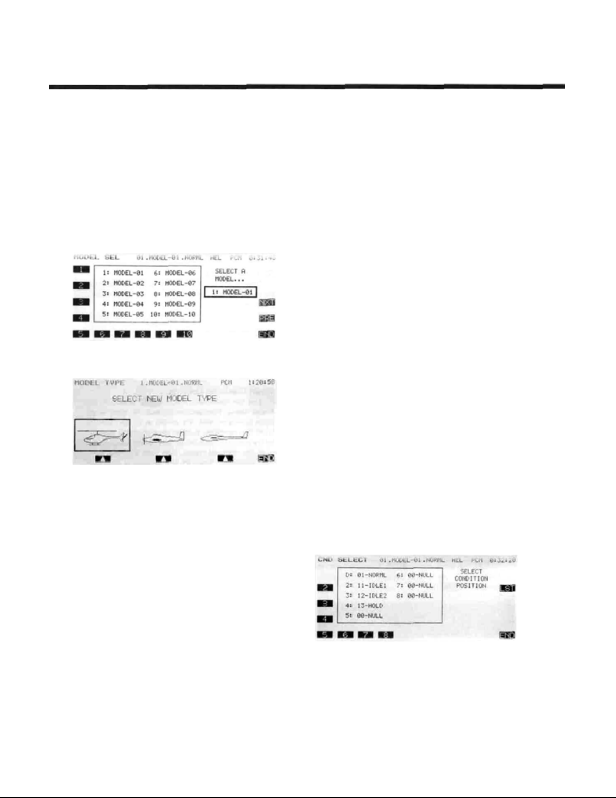
1. Model Selection
Use the Model Select function MSL to select a
vacant model memory (or one you don't mind erasing)
and choose the AIRPLANE Setup using the Type
TYP
function from Model menu.
2. Name The New Model
Rename the model using the Model Name MNA
function in the model menu. Switch to the Condition
menu
CND
(we recommend NORM L). Later you may add other
flight conditions, which may also be named to make
them easier to identify.
3. Activate Special Mixing
Activate Flaperon
ADF
choose one; both require two aileron servos). FPN is
suggested since it can accommodate differential
through end point adjustments, and has Flap mixing.
The Flap mixing is used to have the ailerons behave as
flaps as well, which can be used to make tighter loops
and squarer corners in maneuvers. Use ALV to get
elevators that act as ailerons (two servos are required
for ALV function). You need not adjust the throws
and mixing ratios at this time.
4. Reset Control Order
If necessary, reset the Control Order using the
Function Control
may choose what sticks and sliders control the different functions. If you use the ALV function, move
the retrac t operation to another switch, perhaps CH7
orCH8.
5. Connect Servos
Plug Servos into Correct Channel Numbers
1. AIL Aileron (Ail 1 if FPN or ADF on)
2. ELE Elevator
3. THR Throttle
4. RUD Rudder
5. G EA Landing Gear (Elev 2 if A LV on)
6. FLP Flap ( Ail 2 if FPN activated)
7. AU1
8. AU2 Collective Pitch
9. CH9
6. Set Neutral Points
Use the Subtrim function
servo to its neutral position. If the amount of subtrim
is large, you should reset the subtrim to zero and move
the splined servo arm to a position that is as close to
the desired neutral as possible. Then use the subtrim
to get the neutral position "right on." Repeat with the
remaining channels.
and name the default flight condition
FPN
if you desire these functions (you may only
FNC
Spoiler (Ail 2 if ADF is used)
Channel 9
or Aileron Diferential
in the model menu. Here you
STM
to move each
7. Adjust Servo Throws
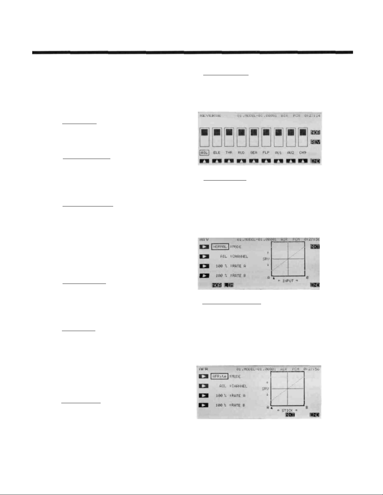
Check the proper direction of throw for each
servo. Use Reversing Function
menu to set proper throw directions for each servo.
Double check that each servo moves the proper direction.
8. Limit Servo Throws
Now use the ATV function to limit servo throws.
The travel of the ailerons should be limited to roughly
10—12° maximum in both directions with the ATV
function. Repeat for elevator. Adjust rudder lateral
motion to about ±45°. Be sure that no servo "bottoms
out" at maximum control throw. After setting maximum throws, ATV is rarely used. Instead use AFR in
the different flight modes.
9. Changing The Control Feel
If you would like to soften the control feel for
ailerons, use the AFR menu. Press the
then the
rate of -15% to -25%. E X2 is used for throttle only.
AF R to get slightly more up than down travel, and use
EX 1 with a -10% setting.
EX1
EX1
key to get exponential curve. Set a
Change to Elevator using the Channel key. Use the
Change to Rudder with the Channel key, and set
for-10%.
REV
in the Model
NXT
key,
Airplane Section, Page 77
Page 2
Airplane Section
10. Set Flaperon Throws
Now go back to the FPN (Flaperon) menu. Set
differential by limiting the down aileron throws on
both sides. The down throw should be set between
70% and 95% of the up throw. This setting depends on
the individual model and its particular flight character-
istics, so make changes after flight testing. Be sure
that the flap mixing settings are the same (default is
±100%).
Move to the E->F menu to set up how much the
ailerons move due to elevator. Approximately 1030% up and down mixing should be used (be sure that
up elevator causes the ailerons to drop, and down
elevator raises the ailerons up). The amount of aileron
droop at neutral elevator may be set with the A knob.
You may adjust this travel by adjusting the trim rate —
it can be set to zer o to prevent accidental changes (be
sure this knob is zeroed before resetting subtrims).
Using the
to turn the elevator-flaperon mixing on and off.
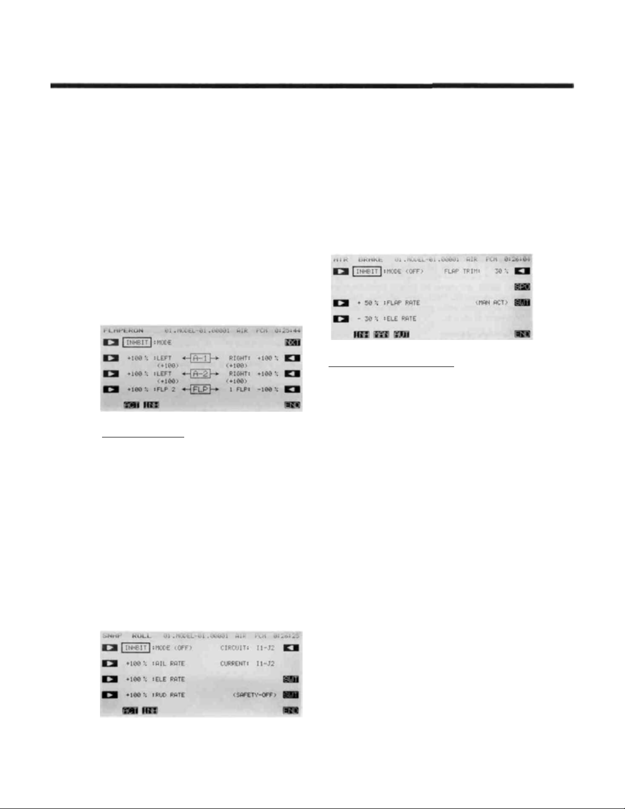
11. Setting Up Airbrakes
move both the elevators and flaps to a preset position
for an airbrake effect. Normally, the ailerons are raised
5—10° and the elevator is offset to cancel any trim
change.
dition menu. Select the Manual mode by pressing the
MAN
mode. To select the operating switch, press the
key. The display shows that the default airbrake con-
trol switch is the C switch, ON in the lower position.
You may choose another switch or direction at this
time. Verify proper operation of the switch by activating it and watching the servos move.
key. If you have spoilers, they may be actuated also.
Read the section on AB K f or more details.
SWT
button, you can also define a switch
To make landings easier, you may set a switch to
Call the Airbrake
key. Auto is available.
This system should normally be used in manual
Press the
PRE
ABK
function from the con-
key to get back to the preceding
SWT
12. Snap Roll Setup
You may have any switch activate the Snap Roll
function (the spring-loaded switch is strongly recommended!). Call the Snap Roll function
the Condition menu. Activate it with the
Set the deflection for each switch position: ailerons
±100-110%, elevator ±80-100%, rudder ±70-80%.
Be sure to choose the correct directions with the
For safety, you may also turn on the safety switch
using the O button. This safety inhibits the activation
of snap roll if the landing gear are down. Check to
mak e su re the s wi t c h is set fo r th e correct direction.
13. Setting Up Differential Elevator
Your PCM 1024Z system has a unique function
called ALV for "Ailevators," or differential elevators.
This function provides roll control whenever the
propeller slipstream is acting on the tail, and is effective at low airspeeds.
Press the
with the
A-3 and A -4 settings. We recommend starting out with
small deflections at first. Be sure that the settings for
ELE are 10 0 % to get full elevator authority.
ALV
key to enter the menu. Activate
ACT
key , then adjust the rates given by the
SNP
ACT
form
key.
Airplane Section, Page 78
Page 3
14.
Flight Conditions Switching
If yo u li ke, you may set up the system to call up
more than one function or switch to a new set of trims
or control settings simultaneously by moving a single
switch. You can have different subtrims, coupling,
differential, exponentials, and throw volumes. In fact
you may change EVERY parameter between flight
modes.
We recommend that you fly the model and adjust
trims and control responses to your liking before
defining another flight condition. Any bad tendencies
may be corrected with custom programmable mix
settings
a new flight condition, where they may be modified
for the new desired conditions. After copying you
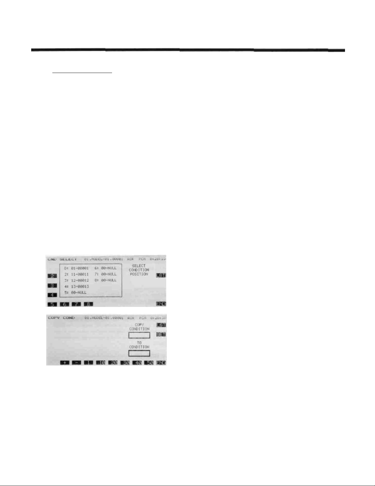
may add new functions as necessary.
Model Menu. This function allocates the necessary
number of flight conditions to the model memory.
Note the condition number next to the D (default) in
the display. This is the set of conditions that wi ll be
copied into a new condition and modified. Also note
the number after the next display. You will copy to
this condition.
menu. This function copies the contents of on e condition into another. Choose the default flight condition
number, press the SET button, then choose the second
condition number in the lower box "TO CONDITION." Give the command to copy.
PMX
. Then, copy the set of adjustments to
Use the Condition Select
Use the Copy Condition
CSL
CPC
from the System
button in the
Airplane Section
15.
Volume Setting
Some functions can have their mixing ratio vary
with the motion of another slider or knob: use the
VOL key O to get to this choice (for example, see
AD F) . Move the selected control to determine how it
affects the mix. You can also add a time delay on
many of the menus: look fo r a DELAY setting.
16. Programmable Mixers
Up to five mixers are available in all flight condi-
tions. These may be used to enhance flight capabilities
or to correct bad tendencies by adjusting mixing from
one control to another. For example, you may use
Elevator->Flap coupling to tighten up the corners on
square loops, Throttle->Rudder coupling to correct
for torque tendencies, etc. There is no limit to the
number of corrections that can be made.
Your PCM 1024Z system is filled with powerful,
predefined mixing functions. Be sure to browse through
the various function menus in the Aircraft section follow-
ing this example.
The switch that calls the flight conditions should
be selected. Return to the Condition Select
function, press the desired flight condition number,
and use the SWT button to choose the desired switch
location. Once you have selected a condition, use the
CNA (Condition NAme) button to label the new conditi on (yo u may have to flip the chosen switch to the
correct position to get the desired condition). Now,
you may go through the Condition menu items to get
the desired settings in the new mode. Read the condition name after the model name to be sure you are
changing the condition you want.
CSL
Airplane Section, Page 79
Page 4
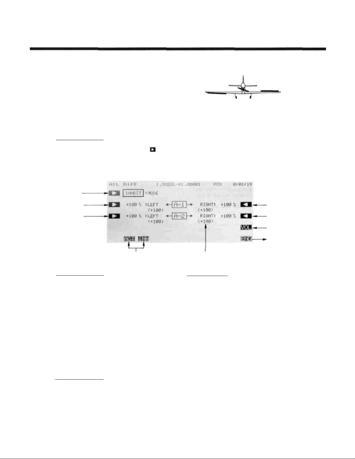
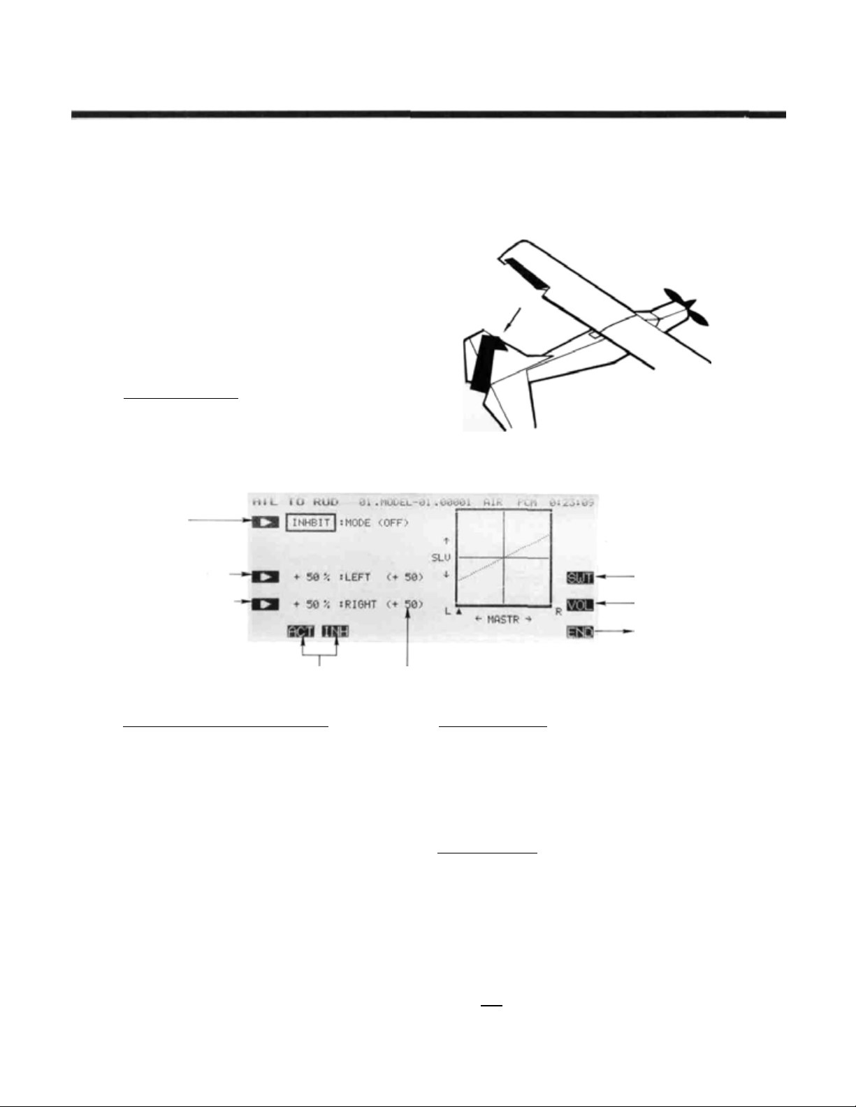
AlLERON DIFFERENTIAL (ADF)
This
function
to independently correct yaw tendencies during
rolls. It is possible to adjust each aileron's positive
and
negative
is activated, receiver outputs CH1 and CH7 are
used for the two aileron channels. This function
may not be used if Flaperon (FPN) is chosen. If
desired, the amount of down aileron deflection
may be trimmed in flight with a knob or trimmer.
Setting Up Aileron Differential
Activation of command
In the Condition Menu, press the ADF key to get the
AIL DIFF menu shown below. Use the A ( ) key to
activate mode setting, then press the
keys (F
and G) to
ferential function.
Mode setting
Aileron 1
Left Side rate
Aileron 2
Left Side rate
uses
deflection
activate or
two
separate
angles.
inhibit
aileron
When
the aileron
Mode selection Values in ( ) are the mixing rate, including the trim volume.
servos
this
function
ACTorINH
dif-
Airplane Section
Aileron 1
Right Side Rate
Aileron 2
Right Side Rate
Trimming volume
Setting
Return to
Condition screen
Aileron 1 Travel Setting
You now set the amount of servo throw for Aileron 1.
Press the B key to activate travel setting for the Left
direction and set the throw with the numeric keys. The
number keys 0 through 100 input the value directly.
The + and - keys increase or decrease the value by 1.
The +/- key may be used to reverse the throw direction.
If you are not sure what you are changing, hold the
stick to one side and press different keys — if there is no
effect, move the aileron stick to the other side and con-
tinue. Your setting may vary from -120 to +120%, the
initial value is+100%.
Now set the travel for the Right throw on Aileron 1.
Press the Q key to activate travel setting fo r the Right
direction and set the throw with the numeric keys as
before.
Aileron 2 Travel Setting
The setting process given above is repeated for Aileron
2. Press the C key to activate travel setting for the Left
direction and set the throw with the numeric keys.
Finally, set the travel for the Right throw on Aileron
2. Press the P key to activate travel setting for the Right
direction and
before.
set
the throw with the numeric keys as
Airplane Section, Page 80
Trim volume setting
You may set up the Aileron Differential function so
that its effect may be changed in flight by moving a trim
control. The trim control adjusts the volume within ±25%
of the set differential rate. This option is not activated at
init i al setup.
Call the volume setting screen by pressing the VOL
O key, and select the desired control using the screen
menus (for a description of the volume setting method,
see page 37).
Use the END (N)
key
to
leave
this
menu.
Page 5
RUDDER COUPLING (A->R)
Airplane Section
This function is used to mix rudder operation
with aileron operation automatically, to make
realistic, coordinated turns. It is especially effective when turning and banking scale models or
large models tha t resemble full -size d aircraft. This
mixing
keeps
the
fuselage aligned
and helps to make what is called "coordinated
turns."
The function allows you to set up the left and
right mixing rates independently. Furthermore,
mixing can be turned on and off during flight by
setting a switch, or it may be set to stay on all the
Setting Up Rudder Coupling
Activation o f command
In the Condition Menu, press the
AI L TO RUD menu, as shown below. Use the A
key to activate mode setting, then press the ACT or
INH
keys ( F and G ) to activate or inhibit rudder
coupling.
Mode setting
into
A->R
key to get the
the
wind
time if the function is activated (ACT) without
setting an ON/OFF switch. Also, it is possible to
adjust the amount of rudder coupling in-flight, by
setting a volume control.
Mixing i—— Left side
rate
setting I—— Right side
Mode Selection Values in ( ) are the mixing rate, including the trim volume.
Setting the Mixing Ratio — Left and R ight
You now set the amount of mixing for left aileron
command. Press the C key to activate mixing ratio for
the Left direction and set the value with the numeric keys
F to M . The number keys 0 through
value directly. The + and - keys increase or decrease
the value by 1. The +/- key may be used to reverse the
throw direction.
If you are not sure what you are changing, hold the
stick to one side and press different keys — if there is no
effect, move the aileron stick to the other side and continue. Your setting may v ary from -100 to +100%. the
initial value is+50%.
Now set the amount of mixing for the Right aileron
command. Press theDkey to activate mixing ratio for
the Right direction and set the throw with the numeric
keys as before.
100
input the
ON/OFF switch
setting
Trimming volume
setting
Return to
Condition screen
On/Off Switch Setting
On initial setting, an activation switch for rudder
coupling is not set. meaning that once activated, it is on
all the time. If y o u would li ke to set a switch to turn it on
and off, call the Switch Setting screen by pressing the
SWT P
switch location and on direction. For more information
on the switch setting method, see page 37).
Trim Volume setting
its effect may be changed in flight by moving a trim control. The trim control adjusts the volume withi n ±25% of
the set mixing rate. This option is not activated at initial
setup.
O
menus (for a description of the volume setting method,
see page 37).
key. Then use the keys to choose the desired
You may set up th e Rudder coupling function so that
Call the volume setting screen by pressing the
key, and select the desired control using the screen
VOL
Use the END (N) key to leave this menu.
Airplane Section, Page 81
Page 6
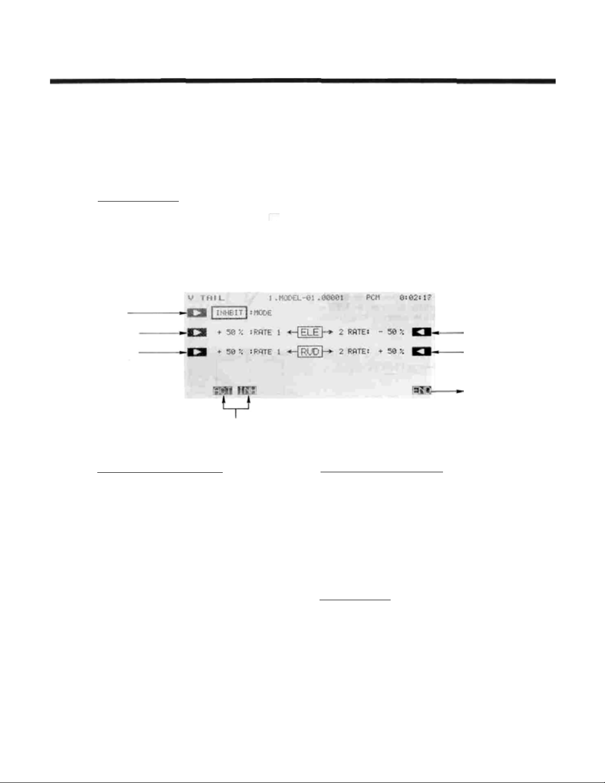
V-TAIL (VTL)
Airplane Section
This
function
1024Z to
control a V-tail airplane with combined
elevator
servos, one hooked up to receiver output CH2
Setting Up V-Tail Mixing
Activation of command
V-TAIL Mixing menu shown below. Use the A key
to activate mode setting, then press the ACT or INH
keys ( F and G) to activate or inhibit V-Tail Mixing.
Mode setting
Elevator 1
deflection angle
Rudder 1
deflection angle
and rudder functions. It requires two
In the Condition Menu, press the
automatically
sets
VTL
up the PCM
key to get the
(elevator 2/rudder) and the second plugged into
CH4 (elevator 2/rudder 1). The elevator and rudder deflection can be adjusted independently.
Elevator 2
deflection
Rudder
deflection angle
Return to
condition screen
angle
2
Mode selection
Setting the Elevator Rates - 1 and 2
You now set the rate for Elevator 1. Press the B key
to activate rate setting for Elevator 1 and set the r at e with
the numeric keys E to M . The number keys 0 through
100
input the value directly. The + and - keys increase or decrease the value by 1. The +/- key may be
used to reverse the throw direction.
If you are not sure what you are changing, hold the
stick to one side and press different keys — if there is no
effect, move t he elevator stick to the other side and con-
tinue. Your setting may vary fr om —10 0 to +100%, the
initial value is +50%.
Now set the rate for Elevator 2. Press the Q key to
activate Elevator 2 rate setting and set the rate with the
numeric keys as before.
Setting the Rudder Rates - 1 and 2
You now set the rate for Rudder 1. Press the C key to
activate rate setting for Rudder 1 and set the rate with the
numeric keys E to M as before.
If you are not sure what you are changing, hold the
rudder stick to one side and press different keys — if there
is no effect, move the rudder stick to the other side and
continue. The initial value is +50%, but your setting may
vary from -100 to +100%.
Now set the rate for Rudder 2. Press the P key to
activate Rudder 2 rate setting and set the rate with the
numeric keys as before.
Checking Your Work
After you have set up the V-Tail rates, be sure that
they move the correct directions. For up elevator command, both V-tails should move upward. For right rudder
command, the trailing edge of both surfaces should move
to the right. If they do not, use the +/- to reverse the
direction as needed.
Use the
END ( N)
key to leave this menu.
Airplane Section, Page 82
Page 7
Airplane Section
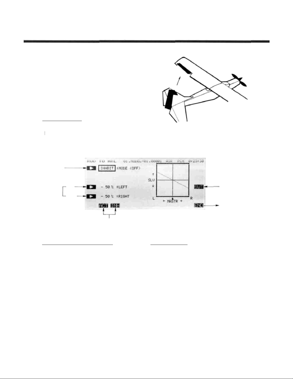
RUDDER—AILERON
Rudder to aileron coupling may be used for
correcting unwanted tendencies with aerobatic
planes. For example, this mixing can be used to
cancel out any rolling that occurs during knife
edge
flight.
The
rates
for
travel can be set independently. Mixing can be set
to be turned on and of f during flight by setting a
switch (if no ON/OFF switch is set, mixing remains on all the time).
Setting Up Rudder-Aileron Mixing
Activation of command
In the Condition Menu, press the A->R key to get the
RUD TO
key to activate mode setting, then press the ACT
or INH
to-aileron coupling.
Mode setting
AIL
mixing menu shown below.
keys(F
andG)
to
activate
(R->A)
left
and
or
inhibit
right
rudder
Use the A
rudder-
Mixing rate
setting
Setting the Mixing Ratio - Left and Right
You now set the amount of mixing for Left rudder
command. Press the C key to activate mixing ratio for
the Left direction and set the value with the numeric keys
E to M
value directly. The + and - keys increase or decrease
the value by 1. The +/- key may be used to reverse the
throw direction.
If you are not sure what you are changing, hold the
stick to one side and press different keys — if there is no
effect, move the rudder stick to the other side and continue. Your setting may vary from -100 to +100%, the
initial value i s -50%.
Now set the amount of mixing for the Right rudder
command. Press the D key to activate mixing ratio for
the Right direction and set the throw with the numeric
keys as before.
Left
Right
Mode selection
The number k eys 0 through 100 input the
ON/OFF switch
setting
Return to
Condition screen
On/Off Switch Setting
On initial setting, an activation switch for rudder to
aileron coupling is not set , meaning t h at once activated, it
is on all the time. If you would like to set a switch to turn
it on and off, call the Switch Setting screen by pressing
SWT P
the
desired switch location and on direction. For more information on the switch setting method, see page 37).
Use the
key. Then use the keys to choose the
END (N
) key to leave this menu.
Airplane Section, Page 83
Page 8
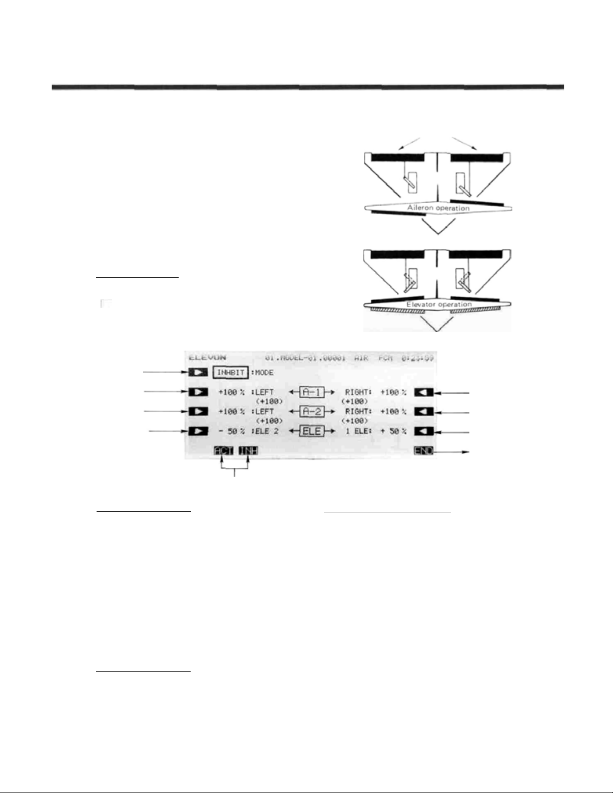
Airplane Section
ELEVONS
This function may be used to set up the controls for delta wings, flying wings, and other tailless
aircraft
elevator functions. Receiver CH1 and CH2 are
made the operating channels for the two elevons,
and differential operation is possible.
The elevator deflection angle and operating
direction can be set for each servo. For conve-
nience, the elevon deflection angles can be trim-
med in flight when a volume-setting lever is activated (this setting is performed by the aileron
differential
Setting Up Elevon Mixing
Activation of command
In the Condition Menu. press the
the ELEVON Mixing menu as shown below. Use the
key to activate mode setting, then press the
or INH keys ( F and G ) to activate or inhibit Elevon
Mixing.
ADF
which
(EVN)
need
function
combined
on
page
125).
EVN
aileron
key to get
ACT
and
Delta-Wing Aircraft
Elevons
A
Mode setting
Aileron 1 left
side rate
Aileron 2 left
side rate
Elevator 2 rate
Mode Activation
Setting the Aileron 1 Rates
You now
B
key to activate left rate setting for Aileron 1 and set
the rate with the numeric keys E to M . The number
keys 0 through
and - keys increase or decrease the value by 1. The
+/-
If you are not sure what you are changing, hold the
stick to one side and press different keys — if there is no
effect, move the a ileron stick to the other side and continue. Your setting may vary from —120 to +120%, the
initial value is +100%.
Now
key to activate Aileron 1 right rate setting and set the rate
with the numeric keys as before.
Setting the Aileron 2 Rates
This
key to activate left rate setting for Aileron 2 and set the
rate with the numeric keys E toMas before.
Now set the right-side rate for Aileron 2. Press the
P key to activate Aileron 2 right rate setting and set the
rate as before.
set
the
left-side
100
key may be used to reverse the throw direction.
set
the
right-side
procedure
is
rate
for
Aileron
1.
Press
input the value directly. The +
rate
for
Aileron
1.
Press
repeated fo r Aileron 2.
Press
Airplane Section, Page 84
theQ
theC
the
Aileron 1 right
side rate
Aileron 2 right
side rate
Elevator 1
Return to
condition menu
Setting the Elevator Rates — 1 and 2
You now set the rate for Elevator 2. Press the D key
to activate rate setting fo r Elevator 2 and set the rate with
the numeric keys
Now set the rate for Elevator 1. Press the O key to
activate Elevator 1 rate setting and set its rate with the
numeric keys.
Checking Your Work
After you have set up the Elevon rates, be sure that
they move the correct directions. For up elevator command, both elevons should move upward. For right
aileron command, the trailing edge of the right-hand
surface should move up, and the trailing edge o f the lefthand surface should move down. I f they do not, use the
+/- to reverse the direction as needed.
Use the END ( N ) key to leave this menu.
E toM
.
rate
Page 9
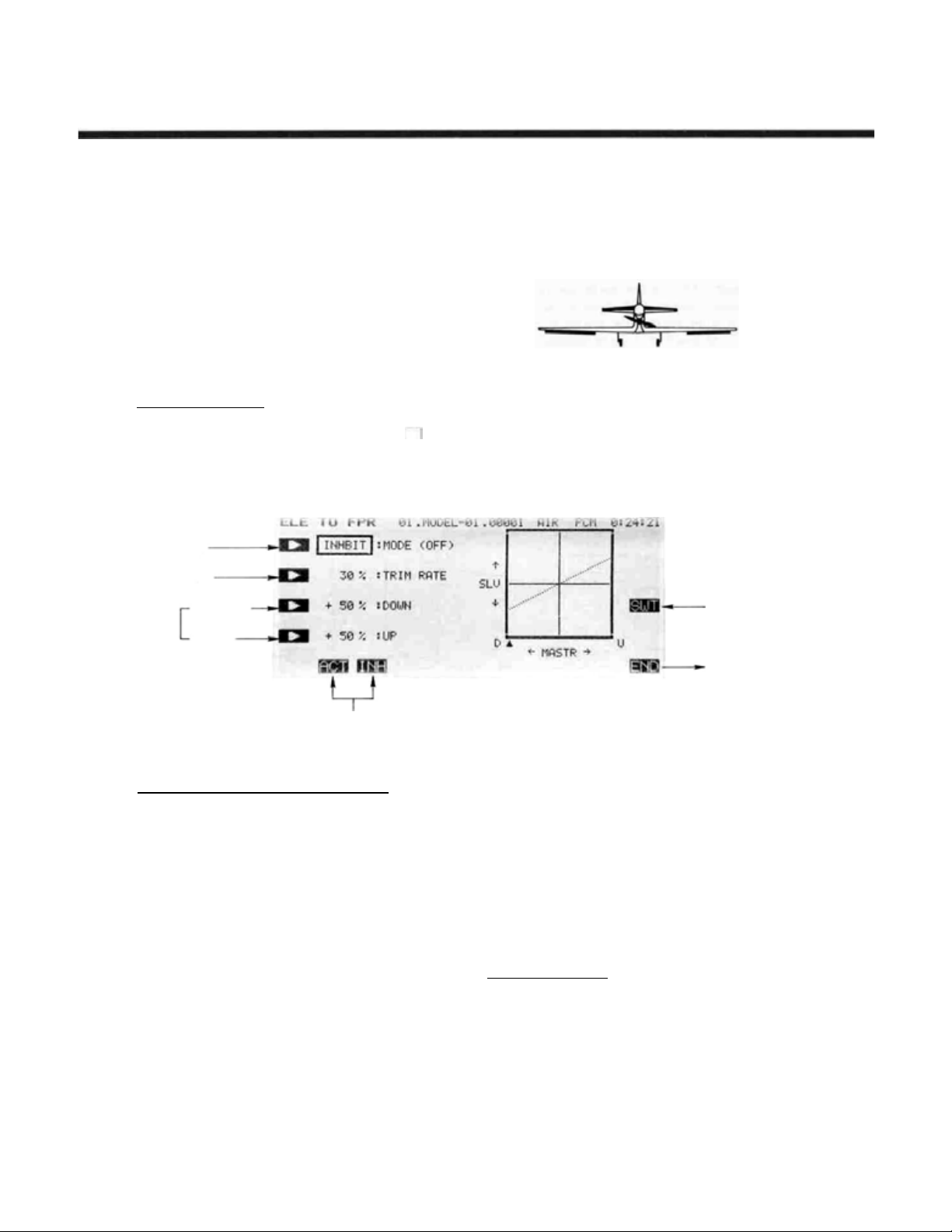
ELEVATOR- FLAP (E-F)
Airplane Section
This mixing is used to droop the flaps whenever
an up elevator command is given (and may be set
up for down elevator as well, helpful during
'outside' maneuvers). It helps to eliminate 'bucking,' and makes tight, square corners in maneuvers
for acrobatic aircraft.
Elevator-to-flap mixing can be set up to be
turned on and of f during flight by a switch (if no
switch is activated, this mixing remains on all the
time).
You
can
also
set
the
flap
trim
rate
in
this
Setting Up Elevator-to-Flap Mixing
Activation of command
In the Condition Menu, press the
ELE TO FPR menu shown below. Use the A key
to
activate
keys ( F and G) to activate or inhibit Elevator-to-Flap.
Mode setting
Flap trim rate
Mixing
rate
setting
mode setting, then
Down side
Up side
E->F
press
the ACT or INH
key to get the
function. If the flaperon function is activated, the
elevators are mixed with the ailerons, otherwise,
the
mixing
is
with
the
flaps
only.
ON/OFF switch
setting
Mode Selection
Setting the Mixing Ratio — Down and Up Side
You now set the amount of mixing for down elevator
command. Press the C key to activate mixing ratio for
the Down direction and set the value with the numeric
keys E to
the value directly. The + and - keys increase or decrease the value by 1. The +/- key may be used to
reverse the throw direction. Your setting may vary from
-100 to +100%, the initial value is set to +50%.
Now set the amount of mixing for the up elevator
command. Press the D key to activate mixing ratio for
the Up direction and set the throw with the numeric key s
as before.
M
The number keys 0 through
100
input
Return to
Condition screen
Flap Trim Rate Setting
You may choose any value for the Flap Trim Rate.
Knob (A) is used to trim the position of the flap servo,
and the trim value controls the authority of the knob.
The authority may be set anywhere from 0% to 100%,
and the initial setting is 30%.
Call the flap trim setting screen by pressing the TRIM
RATE B key, and select the desired trim rate using the
screen menus. You may want a small number fo r th i s rate,
so that an accidental movement of the knob doesn't give a
large flap deflection.
On/Off Switch Setting
On initial setting, the activation switch for Elevator-toFlap mixing is set as SW (C) on at the upper position. If
you would li ke to change the switch or turn mixin g on all
the time, call the Switch Setting screen by pressing the
SWT P
key. Then use the keys to choose the desired
switch location and on direction. For more information
on the switch setting method, see page 37).
Use th e
END ( N )
key to leave this menu.
Airplane Section, Page 85
Page 10
Airplane Section
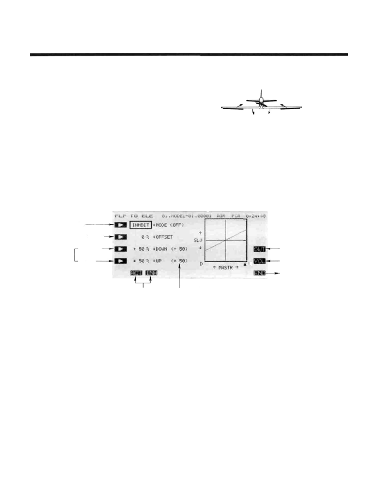
FLAP-ELEVATOR
This
function
changes when flaps are deployed for show fli g h t or
landing by mixing in a small movement of elevator.
The elevator should be adjusted to move only a
small deflection amount: too much elevator can
make the model difficult to control.
The amount of correction can be adjusted sepa-
rately for both positive and negative flap inputs,
and the neutral mixing position can be offset from
the flap neutral position. Flap-to-elevator mixing
can be turned on and off during flight by setting a
switch, but if an ON/OFF switch is not set, it
remains on al l the time. The amount of mixing can
be changed by setting a volume control.
Setting Up Flap-to-Elevator Mixing
Activation of command
In the Condition Menu, press the
FLP TO ELE menu shown below.
Mode setting
is
used
Mix (F-E)
to
compensate
F-E
for
trim
key to get the
Offset amount setting
Mixing
rate
setting
Use the A ( ) key to activate mode setting, then press
the ACT or INH
inhibit flap-to-elevator coupling.
Offset Position Setting
Then set the flap control to the offset position, and
press the SET key F to store the desired position in
memory.
Setting the Mixing Ratio — Down and Up Side
mand. Press the C key to activate mixing ratio for the
down direction and set the value with the numeric keys
E to M .
value directly. The + and - keys increase or decrease
the value by 1. The +/- key may be used to reverse the
throw direction. Your setting may vary from —100 to
+100%, the initial valu e is set to +50%.
command. Press the D key to activate mixing ratio fo r
the Up direction and set the throw with the numeric keys
as before.
Down side
Up side
Mode Selection Rate including volume adjustment
keys
(F and G)
Use the B key to activate offset setting mode.
You now set the amount of mixing for down fla p com-
The number keys 0 through
Now set the amount of mixing for the up elevator
to
activate
or
100
input the
ON/OFF switch
setting
U
On/Off Switch Setting
Initially an activation switch for is not set, meaning
tha t once activated, this function is on all the time. If you
would like to set a switch to turn it on and off, call the
Switch Setting screen by pressing the
Then use the keys to choose the desired switch location
and on direction. For more information on the switch
setting method, see page 37.
Trim volume setting
You may set up the Flap-to-Elevator mixing so that its
effect may be changed in flight by moving a trim control.
The trim control allows you to adjust the volume within
±25% of the set mixing rate, which can be handy for
getting the best value while flying the model. This option
is not activated at initial setup.
Call the volume setting screen by pressing the VOL
O key, and select the desired control using the screen
menus (for a description of the volume setting method,
see page 3 7 ).
Use the
END
N key to leave this menu.
Trimming volume
setting
Return to Condition
screen
SWT P
key.
Airplane Section, Page 86
Page 11
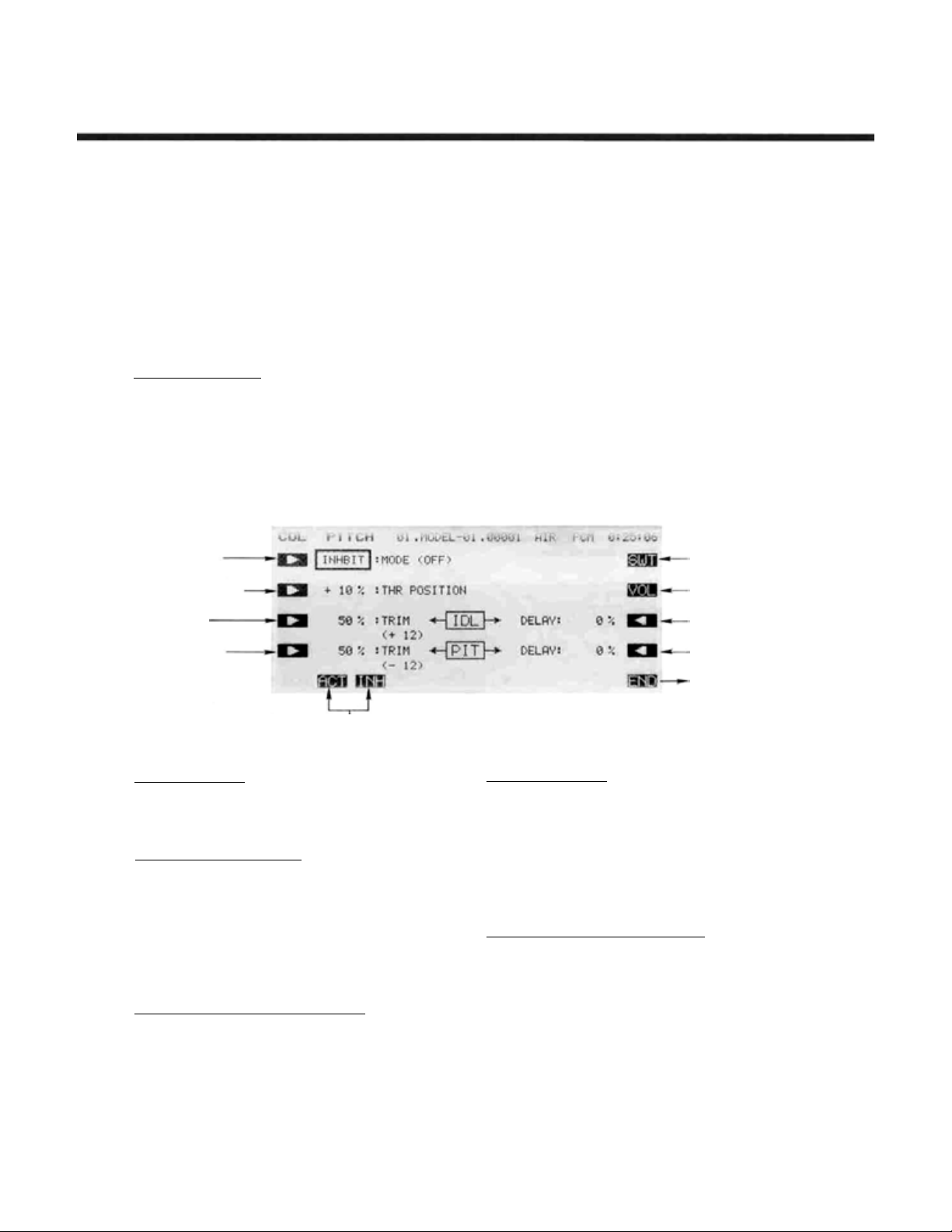
COLLECTIVE PITCH FUNCTION (CPT)
(DIVING
AIR
BRAKE,
HIGH
PITCH
TRIM)
Airplane Section
This function allows diving airbrake ("minus
pitch") adjustment at low throttle and high pitch
adjustment at high throttle for consistent model
speed during vertical aerobatics. This mixing can
be turned on and off during flight with a switch.
Air brake, engine idle-up trim , and t he high-side
pitch control trim can be set independently.
Setting Up Collective Pitch Function
Activation of command
In the Condition Menu, press the
COL PITCH menu shown below. Use the
key to activate mode setting, then press the ACT or
INH keys ( F and G ) to activate or inhibit the func-
tion.
Mode setting
Mixing operation
point setting
Idle-up
High pitch
Trim Rate setting
CPT
Mode selection
The
key to get the
A
mixing switching point (minus pitch/high pitch
switching point) can be set at a selected throttle
stick position, and each trim rate can be adjusted.
The throttle delay when switching from minus
pitch to high pitch and the pitch delay when
switching from high pitch to minus pitch can also
be adjusted independently.
ON/OFF switch
setting
Trimming volume
setting
Throttle delay
setting
Pitch delay
setting
Return to
Condition screen
Switch Point Setting
Press the B key to enter the thro ttle position setting
function. Then set t he throttle stick to the desired switch
key
to enter the
SET (F)
point, and press the
Idle-up Trim and Delay Setting
Press the C key to enter the Idle-Up Trim rate setting
function, and set the rate with the numeric keys F to
M. The range may be set from 0 to 100%, and the initial
value is set to 0%.
Next, press the P key to enter the Throttle delay
setting function, and set the delay with the numeric keys.
The setting range is 0 to 100%, an d the initial value is set
to0%.
Pitch Control Trim Rate and Delay Setting
Press
the D
function. Set the desired rate with the numeric keys F to
M.
The range may be set from 0 to 100%, and t he initial
value is set to 50%.
Press the O key to activate the Pitch Delay setting
menu, and set the delay with the numeric keys
The range may be set from 0 to 100% (initial setting is
0%).
key.
Pitch
Trim
Rate
setting
F to M .
Airplane Section, Page 87
On/Off Switch Setting
On initial setting, the activation switch for the Collective Pitch function is set as SW (E) ON at the lower position. If you would like to change the switch or turn
mixing on all the time, call the Switch Setting screen by
pressing the
choose the desired switch location and on direction. For
more information on the switch setting method, see page
37).
Idle-Up Trim/Pitch Co ntrol Trim Setting
You may set up the Collective Pitch function so that
its effect may be changed in fli ght by moving a trim control. The trim control allows you to adjust the volume by
moving a slider. A t initial setting, the left-side lever is set
for idle-up trim and the right-side lever is set for pitch
control trim.
Call the volume setting screen by pressing the
O key, and select the desired control using the screen
menus (for a description of the volume setting method,
see page 37).
Use t he
SWT(R)
END
(N) key to leave this menu.
key. Then use the keys to
VOL
Page 12
AlLEVATORS/COMBINED AlLERONS & ELEVATORS (ALV)
This
function
tor surface on each side of the airplane independ-
ently,
so
mode) and differentially (aileron mode). This
function,
give aileron control even at low speeds, because
the
propeller
surfaces and may be used f or rolling commands.
This function requires two elevator servos connected to receiver output channels 2 and 5. In this
manual (see diagram), the rear control su r faces are
referred to as Aileron 3 and Aileron 4. With this
function, all control deflections — left and right
ailerons,
adjusted. You may even add differential to the rear
ailerons.
and
allows
you
that
they
operate
sometimes called
wash
is
always passing over
elevator
on
to
hook
together
"ailevators"
both
sides
up
the
(elevator
(ALV)
—
the
can
eleva-
will
tail
be
Airplane Section
Setting Up Differential
Activation of command
In the Condition Menu, press the ALV key to get the
AILVATOR menu shown below. Use the A key to
activate mode setting, then press the ACT or INH
keys (F andG)to activate or inhibit the function.
Mode setting
Aileron 3 Left.
Side Rate
Aileron 4 Left
Side Rate
Elevator 1 Rate
Setting
Setting the Aileron 3 Rates
You now set the left-side travel for Aileron 3. Press the
B ke y to activate left rate setting fo r Aileron 3 and set
the rate with the numeric keys E to M . The number
keys 0
through 100
and - keys increase or decrease the value by 1. The
+/-
key may be used to reverse th e throw direction.
Your setting may vary from -100 to +100%,the initial
value is-50%.
Now set the right-side rate fo r Aileron 3. Press the Q
key to activate Aileron 3 right rate setting and set the rate
with the numeric keys as before.
Setting the Aileron 4 Rates
This procedure
key to activate left rate setting for Aileron 4 and set the
rate with the numeric keys E to M as before. The max
values and initial setting are t he same as for Aileron 3.
Now set the right-side rate for Aileron 4. Press the 13
key to activate Aileron 4 right rate setting and set the rate
as before.
input
is
repeated
Elevators
Mode Activation
the
value
for
directly. The +
Aileron
4.
Press
the C
Aileron 3 Right
Side Rate
Aileron 4 Right
Side Rate
Elevator 2 Rate
Setting
Return to
condition menu
Setting the Ele va to r Rates - 1 and 2
You now set the rate for Elevator 1. press the D key
to activate rate setting for Elevator 1 and set the rate with
the numeric keys E to M . The initial rate is 100%, but
you may vary your setting between -100 and +100%.
Now set the rate for Elevator 2. Press theOkey to
activate Elevator 2 rate setting and set its rate with the
numeric keys. Settings have the same range as Elevator 1.
Checking Your Work
After you have set up the Ailevator rates, be sure that
they move the correct directions. For up elevator command, both elevators should move upward. For right
aileron command, the trailing edge of the right-hand
surface should move up. and the trailing edge o f the lefthand surface should move down. I f they do not, use the
+/- to reverse the direction as needed. Adjust the
travels on either side to get the differential effect, if you
wish.
Exiting
Use the
END ( N
) key to leave this menu.
Airplane Section, Page 88
Page 13
Airplane Section
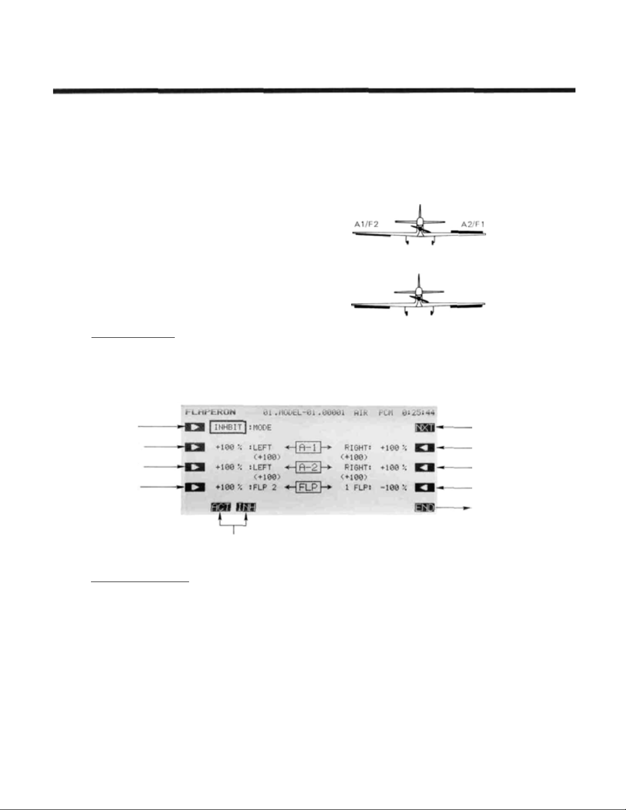
FLAPERONS
This function allows you to program the
ailerons to work in the same direction, giving a
flap response as well as aileron control (see figure).
For good square maneuvers, and landing, both
ailerons can be raised and lowered simultaneously.
While this function is on, regular aileron operation
is always present.
The Flaperon function requires two separate
channels: Receiver CH1 (aileron 1/flap 2) and CH6
(aileron 2/flap 1) are the operating channels. The
Aileron 1 and Aileron 2 left and right deflection
angles can be adjusted independently, making it
easy to apply differential to the ailerons. With
differential, the up side travel is set to around 5%
larger than the down travel.
Setting Up Flaperons
Activation of command
In the Condition Menu, press the
FLAPERON menu as shown below. Use the A ke y
to activate mode setting, then press the
keys
(F and G) to
activate or
(FPN)
inhibit
the
FLP
function.
key to get the
ACTorINH
You may also adjust the
throws independently, and you can set the flap
trim
rate
as
large
or
small
flap trim offset can be adjusted, allowing you to
freely change the flap neutral angle.
Aileron operation
Flap operation
as
Flap
you
like.
1 and Flap 2
Also,
the
Mode setting
Aileron 1 Left
Side Tra ve l
Aileron 2 Left
Side Travel
Flap 2 Travel
Setting
Mode Selection
Setting the Aileron 1 Travel
You now set the left-side travel for Aileron 1. Press the
B
key to activate left travel setting for Aileron 1 and set
the travel with the numeric keys E to M . The number
keys 0
through 100 input the
and - keys increase or decrease the value by 1. The
+/- key may be used to reverse the throw direction.
If you are not sure what yo u are changing, hold the
stick to one side and press different keys — if there is no
effect, move the aileron stick to the other side and continue. Your setting may vary from —120 to +120%, wit h
an initial value of +100%.
Now set the righ t-side travel f or Aileron 1. Press the
Q
key to activate Aileron 1 right travel setting and set
the travel with the numeric keys as before.
value
directly. The +
To Next Screen
Aileron 1 Right
Side Travel
Aileron 2 Right
Side Tra vel
Flap 1 Travel
Setting
Return
to
condition menu
Setting the Aileron 2 Travels
This procedure
key to activate left travel setting for Aileron 2 and set the
travel with the numeric keys E to M as before.
Now set the right-side travel for Aileron 2. Press the
P key to activate Aileron 2 right travel setting and set
the travel as before.
Setting the Flap Travels — 1 and 2
You now
activate travel setting for Flap 2 and set the travel with
the numeric keys E to M . Your setting may va ry fro m
-100 to +100%, with an initial value of +100%.
Now set the travel for Flap 1. Press the
activate Flap 1 travel setting and set its travel with the
numeric keys. I ts initial value is -100%.
is
repeated for Aileron 2.
set
the
travel
for
Flap
2.
Press
Press
the D key
O
theC
to
key to
Airplane Section, Page 89
Page 14

Flap Trim Authority Setting
In the Flaperon mode. Flap Trim moves both ailerons
upwards or downwards together. To input the Flap Trim
Authority, move to the next screen by pressing the
R key. Then press theDkey and set the rate with the
numeric keys F to M. You may choose any value from
0% to 100% f or the Flap Trim Authority. The initial
setting is 30%, but a smaller number is recommended.
Flap Trim Offset Setting
Flap trim offset sets the flap position from which
motion occurs. To input the flap trim offset amount
setting, press th e B key, then set the flap trimmer to the
position to be set and press the
can be anywhere between ±(trim authority setting).
Checking Your Work
After you have set up everything, be sure the controls
move the correct directions. If they do not, use the +/-
to reverse the direction as needed.
SET
F key. The offset
NXT
Airplane Section
Use the
to get to the previous menu.
END
( N) key to leave this menu, or hit PRE
Airplane Section, Page 90
Page 15
Airplane Section
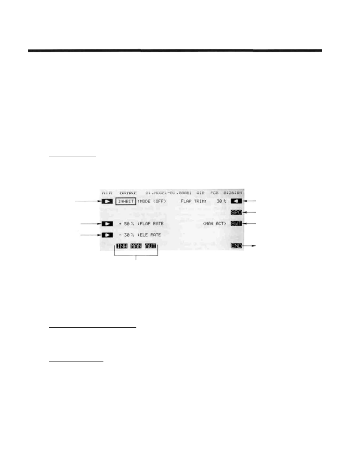
AIRBRAKE
Airbrake presets are used to set up preset
deflections of the elevators, flaps, and (optionally)
spoilers for landing precision or for constant speed
during vertical flight maneuvers. Airbrake presets
can be turned on and off during flight by ON/OFF
switch, or you may define an AUTO mode where
mixing is turned on and off automatically by
throttle stick position.
The AUTO mode, if used, may be turned on
and off with a switch. However, a command on
Setting Up The Airbrake Presets
Activation of command
In the Condition Menu, press the
AIR BRAKE menu as shown below.
Mode setting
Flap Preset
Position Setting
Elevator Preset
Position Setting
(ABK)
ABK
key to get the
the
air
brake
has
priority
of the position of the AUTO mode ON/OFF
switch.
Suggested settings for the Airbrake function are
a flap deflection of +50%. The elevators will need
to be set to about -20 to 23%. Of course, the
elevators should be adjusted so that the model
maintains
is operated.
level
flight
when
and
is
followed
the
Airbrake
Flap Trim Rate
Setting
Spoiler Setting
Air brake ON/OFF
Switch Setting
regardless
function
Airbrake Mode Selection
Use the A key to activate mode setting, and
press the ACT F key to activate the function. Now
you must decide on Manual or Auto operation. Select the
manual mode by pressing the MAN ( G) key. Select the
AUT
auto mode by pressing the
Throttle Position Setting (Auto Mode Only)
For the Auto mode, you need to input the position at
which the function will take effect. Press t h e B key, then
move the throttle stick to the desired position, and press
SET
the
Flap Preset Position Setting
the C key and use the rate setting keys
setting may vary from -100 to 100%, and is initially set
to
( F ) key to memorize the position.
To set the position that the fla ps will move to, press
50%.
H key.
E to M
. This
Return
to
condition menu
Elevator Preset Position Setting
To set the position that the elevators will move to,
press the D key and use the rate setting keys E to M .
This setting may vary from -100 to 100%, and is initially
set to -30% by the system.
Flap Trim Authority Setting
Flap Trim moves both ailerons upwards or downwards
together. To input the Flap Trim Authority, press the
NXT R
key. Then set the rate with the numeric keys
E to M. You may choose any v alue from 0% to 100%
for the Flap Trim Authority. The initial setting is 30%,
but a smaller number is recommended. If you input a
number here, it will override whatever value was input in
the Flaperon menu.
Airplane Section, Page 91
Page 16
Airplane Section
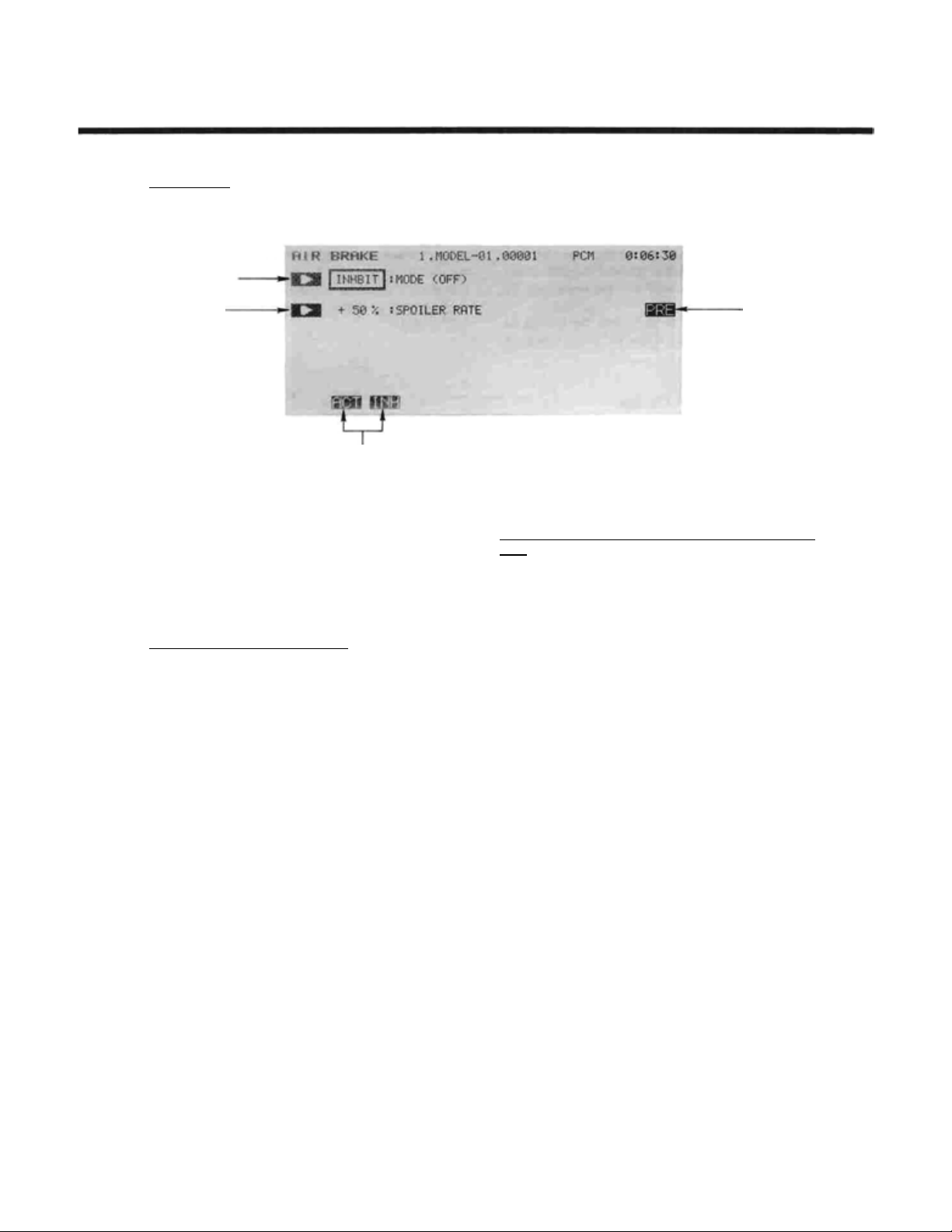
Spoiler setting: Press the
menu below.
Spoiler Activate
Spoiler Preset
Setting
Use the A () key to activate mode setting, then
press the
or inhibit the function. Press the B key and set the rate
with the numeric keys E to M . The initial spoiler preset
is 50%, but you may set it between -100 and +100%.
Return to preceding screen by pressing the Q key.
Airbrake ON/OFF Switch Definition
SW (C ) is turned ON at the lower position at initial
setting. If you'd like another switch, call the switch
setting menu by pressing the SWTPkey. For a description of the switch setting method, see page 37.
Caution: if the ON/OFF switch is disabled with NUL, the
Airbrake function remains on all the time.
ACTorINH
SPO Q
key to get to the
Spoiler Mode Selection
keys ( F andG)to activate
To Preceding
Screen
Auto ON/OFF Airbrake Switch Definition (AUTO mode
only)
At first setting, the automatic airbrake control switch
is defined as SW (E), ON at the lower position. To change
this, call the switch setting menu by pressing the
O
key. For a description of the switch setting method,
seepage37.
Use the
END N
key to exit this menu.
SWT
Airplane Section, Page 9 2
Page 17
Airplane Section
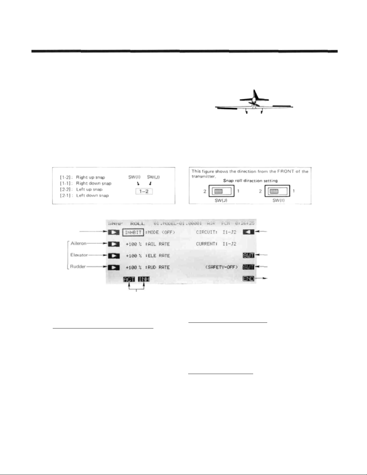
SNAP ROLL
Your PCM 1024Z system may be programmed
to perform snap rolls by flipping a switch. Four
snap roll directions can be defined, and the preset
positions of the aileron, elevator, and rudder
servos can be set f or each one.
You may activate a safety switch to ensure that
snap rolls are not accidentally commanded while
the
landing
switch is turned on accidentally.
Setting Up The Snap Roll Presets
Activation of command
In the Condition Menu, press the
SNAP ROLL menu as shown below.
Snap Roll Directions
(Note: These snap roll direction se tt i ng switches are only present on the T9ZAP systems, not on the T9ZHP)
gear
(SIMP)
is
down,
even
if
the
SNP
snap
roll
key to get the
Direction Switches
Mode setting
Rate
setting
Mode selection
Use the
press the
or inhibit the function.
Inputting the Snap Roll Preset Control Positions
We'll start with the 1-2 direction (Right/Up) snap
roll setting. Press the R key to get to the setting menu,
then press the
To
key. Use the numeric keys
preset condition. The default is +100%, but you may use
anything between -110 and +110%.
Now we'll set the Elevator servo preset. Press the C
key. and set the preset with the numeric keysEtoM.
This also has a default of +100%, but you may use anything between -110 and +110%.
The last part of the setting is for the rudder position.
Press the D key, and enter the rate that you want the
rudder to move with the numeric keys E to M. This
setting also has a default of +100%, and may be set anywhere between -110 and +110%.
This procedure should be repeated for the
direction (Rright/Down) snap roll setting,
A
ACTorINH
set
the Aileron
key to activate mode setting, then
keys ( F and G ) to activate
1-2
F key.
servo
throw setting,
E to M
press
to input the desired
2-2
direction
theB
-Th row setting
ON/OFF switch
setting
Safety switch setting
Return to condition
menu
(Left/Up) snap roll setting, and 2-1 direction (Left/
Down) snap roll setting.
Snap Roll Switch ON/OFF Definition
SW (H) is defined to be the Snap Roll switch, and is
turned ON at the forward position at initial setting. If
you'd like another switch, call the s witch setting menu by
pressing the
switch setting method, see page 37. Caution: if you define
a switch that doesn't have a spring return, the Snap R oll
function will remain on all the time!
Snap Roll Safety switch setting
A safety switch should be used to prevent accidental
operation of the snap roll function. To examine the snap
roll safety switc h settings, call up the switch setting screen
by pressing the SWT
defines SW (F) for Mode I, (G) for Mode II to be the
safety switch. You should set the ON direction of the
safety switch to match the landing gear switch position
when the landi ng gear is down. When this switch is ON,
1-1
the snap roll function is inhibited.
Use the
SWT
P key. For a description of the
END N
key to exit this menu.
O
key. The function initially
Airplane Section, Page 93
Page 18
Airplane Section
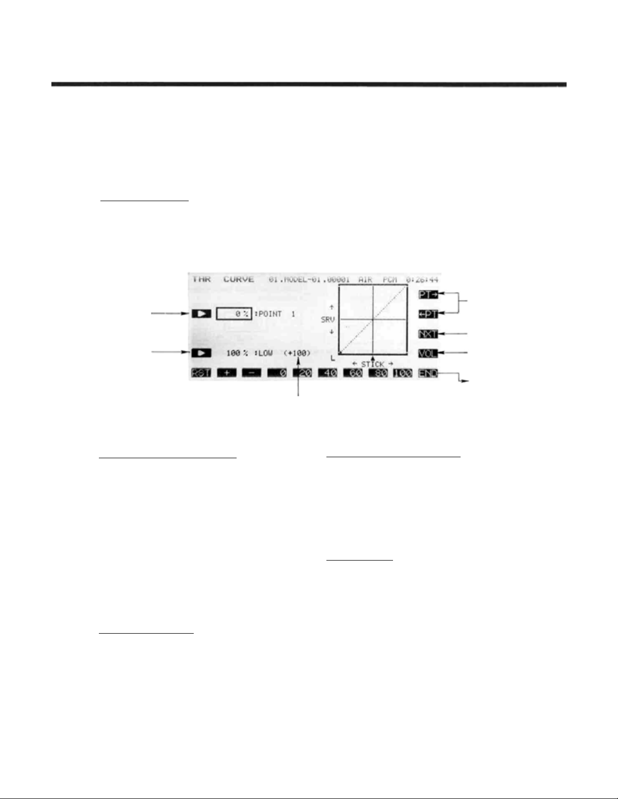
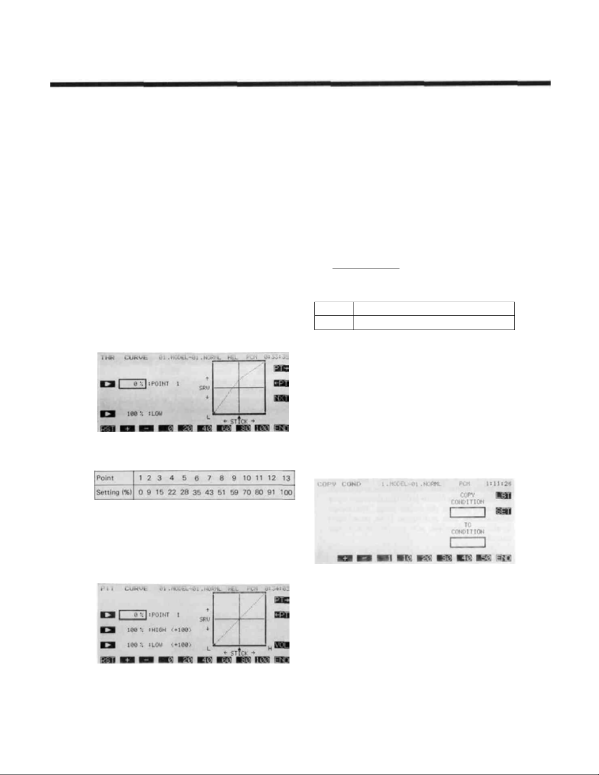
THROTTLE CURVE
This function programs throttle curves for dif-
ferent
flight
modes.
servo
response
by a 13-point curve. The low side rate can be adjusted with a volume control (point 7 is the refer-
Setting Up The Throttle
Throttle Curve Inputting
In the Condition Menu, press the
the THR CURVE menu shown in the figure below.
Curve setting
Low Side
Rate Setting
over
The
full
ADJ. (TCV)
throttle
stroke
Curve Function
of
curve
the
throttle
TCV
sets
the
stick
key to get
ence).
The
servo
delay
at
flight
condition
can also be programmed. You need to activate the
Model menu throttle curve [THR] function (page
53) to allow the Throttle curve function to work
properly.
switching
Point Movement
Trim Volume
Setting
Low Side Rate Set Value, Including Trim Volume
Setting Point Selection (Points 1 to 13)
Press
the Bkey
function. Use the movement keys Q and R to select the
point whose value is to be set. The
the poin t number by one, and the
point number by one. The active point on the curve is
shown as a black dot.
Once you have selected the desired point on the curve,
you may input the rate with the rate setting keys E to
M.
The number keys 0 through
directly. The
value by 0.5 with each button pressing (so it takes two
hits to see a number change because of numeric rounding).
You may set or reset each point on the curve by
repeating these steps for each point.
Low-Side Rate Adjustment
Press
the D
numeric keys E to M . You may set anywhere in the
range fro m 0 to 110% (initially the rate is set to 100%).
to
tur n on the curve
+
and - keys increase or decrease the
key
and you may
<-PT
input
inputting
PT->
key increases
key reduces the
100
input the value
the rate
with
the
Return To
Condition Menu
Low-Side Volume Control Assignment
No volume controller is defined when TCV is first
activated. To set the control and direction of the volume
adjuster, call the volume setting screen by pressing the
VOL O
key. Use the buttons to selec t the control and
direction you desire. For a description of the volume
setting method, see page 37.
Use the
or use the END
to the Condition menu.
Curve Setting Note
If you change Point 7 after setting the low side rate,
other points in the throttle curve also change, because
Point 7 is the reference point for the curve.
PRE N
key to return to the previous menu,
N
key to leave this menu and return
Airplane Section, Page 94
Page 19
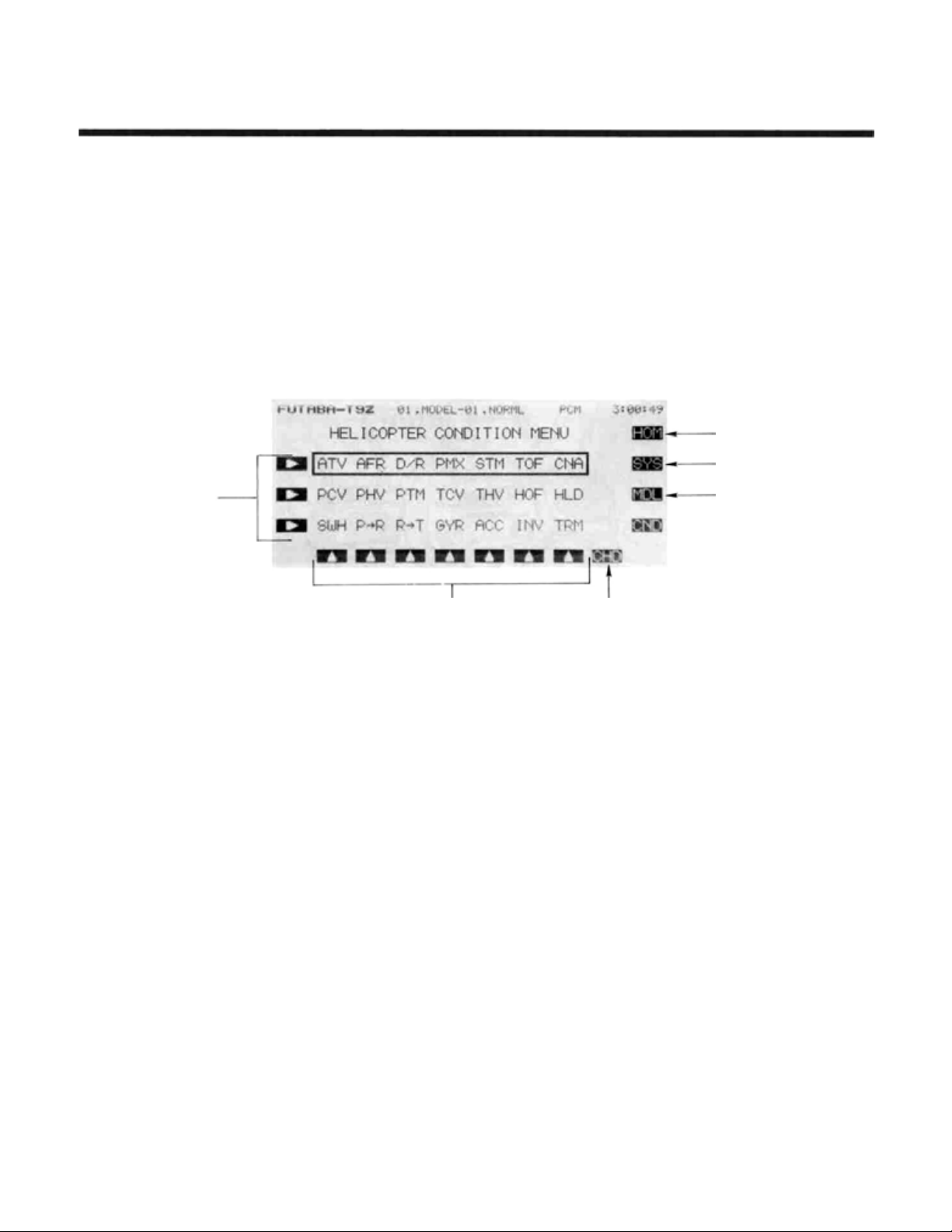
HELICOPTER SECTION
This section contains information on the commands that apply to
helicopters only. Each of these functions can be set independently for
different flight conditions.
To get to these settings, press the MDL key from any menu in a
Helicopter setup. To select one, first select the line containing the
desired function with the B , C, or D keys. Then use the F to
L keys to select the function to be entered.
For conditions that apply to all models (ATV, AFR, D/R, PMX,
STM, TOF, CNA, and TRM functions), refer to the Common Condi-
tions section. For instructions on Airplanes and Sailplanes, refer to
the sections pertaining to those airc raft.
Select Desired
Line With
These Keys
Helicopter Section
To Home Screen
To System Menu
To Model Menu
Function Selection Keys Activates Condition Hold Function
Helicopter Section Table of Contents
Helicopter Transmitter Controls and Functions.
Helicopter Receiver and Servo Connections.
Helicopter Setup Example.
Specific Control Setup Definitions
PCV.
. .
.Pitch Curve
PHV. .
.Hovering
PTM
. .
.Pitch
Trim
TCV
. .
.Throttle
THV
. .
.Hovering
HOF
. . .Hovering
HLD. .
SWP. . .
P->R
R->T
GYR. .
ACC .
INV. . . .Inverted
.Throttle Hold
.Swashplate Type
. . .Pitch->
. . .Rudder -> Throttle
.Gyro
.
.Acceleration.
Rudder
Sensitivity.
............................
..........
Pitch.
........
...........
Curve.
........
Throttle.
Offset.
Pitch . ......
......
.......
......
.......
........
......
.......
.........
.Adjusts
flight conditions
.Used
around hover
.Allows pitch
without changing curve
.Program
throttle response
.Can adjust
around hover
.Programs
point
.Moves
during autorotation
.Compensates
cyclic applied
.Handles torque changes
pitch angle inputs
.Accounts
to rudder
.Used
.Cancels torque due
throttle commands
Sets
flight
to
to
pitch
................ 96
.................. 98
99
response
trim
the
for
switch
pitch
the
throttle
pitch
throttle
power
rates
in
different
response
trim
offset
shape of
response. . . .
mix
to
for
power
change
gyro
to
for
inverted
. . . 104
. . . .
......
the.
.....
hovering
...
idle
.....
loss
when 111
from . . . 112
due. . .
sensitivity . .
sudden
. . .
....
105
106
107
108
109
110
.113
114
116
117
Helicopter Section, Page 95
Page 20
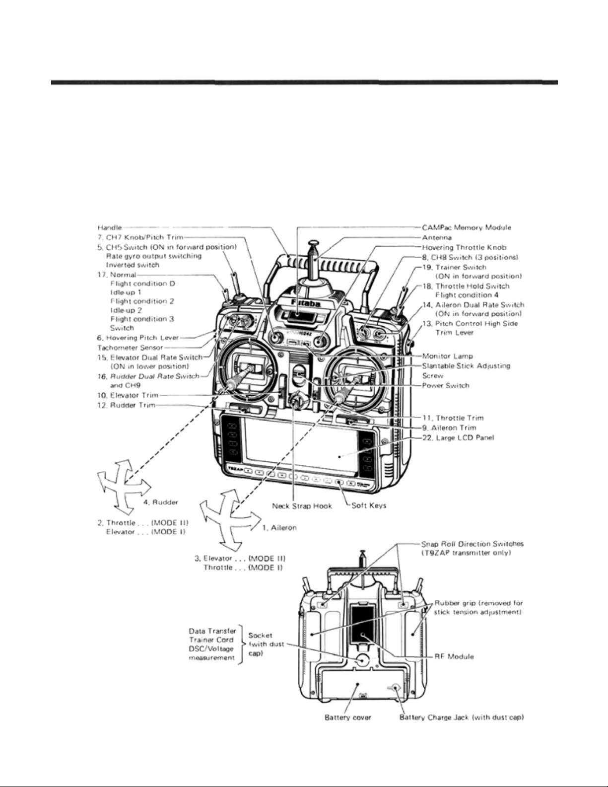
HELICOPTER TRANSMITTER CONTROLS AND FUNCTIONS
Functions and locations given in this drawing are
the factory default positions, which occur upon
startup. Each setting can be easily changed as the
owner desires. The Function Change menu [FNC]
may be used for this purpose.
Helicopter Section
Helicopter Section, Page 96
Page 21

Note that all stick & switch positions may be
changed
1.
Aileron control
2.
Throttle control . . . (MODE II)
Elevator control . . . (MODE I)
3.
Elevator control . . . (MODE II)
Throttle control
4.
Rudder control
5.
CH 5 switch
Rate gyro output switching/inverted switch.
6.
Hovering rate lever (CH6)
Adjusts the hovering point pitch
independently from the thr o t tle.
pitch trimming when hovering. When t h e
throt t le stic k is at the SLOW or HIGH side,
the pitch servo does not operate ev en if this
lever is moved.
7.
CH7/pitch trim knob
Used as a spare channel, or as the pitch
trimmer.
8.
CH8 switch
Used as a spare channel (3 positions).
9.
Aileron trim lever trims the ailerons.
10.
Elevator
11. Throttle trim lever (with ATL) Adjustable
throttle limiter type trim lever. Operates at
the throttle stick SLOW side. Movement is
maximum at maximum slow. Since the HIGH
side does not change even if the SLOW si de is
adjusted, it is very convenient when
connecting the linkage, etc.
trim
. . . (MODE I)
lever
trims the
Used in
elevators.
Helicopter Section
12. Rudder trim lever trims the rudder.
13. Pitch control HIGH side trim lever.
Pitch control servo HIGH pitch trimmer.
Adjusted for optimum pitch during flight.
14. Aileron dual rate switch.
Aileron deflection angle
15. Elevator dual rate switch.
Elevator deflection angle
16. Rudder dual rate switch.
Rudder deflection angle switch.
Can also be used as the CH9 switch.
17. Normal/idle-up 1/idle-up 2 switch.
Idle-up ON/OFF switch.
The On direction is set by condition
(CSL) function (page 40).
(Flight condition switch.)
18. Throttle hold switch.
This switch is used during auto rotation.
The ON direction is set by condition select
(CSL) function (page 40).
(Flight condition switch)
19. Trainer switch.
This switch is turned on in the forward
position. It is spring loaded and is turned off
when released. It can also be changed to an
alternate switch (page 29).
switch.
switch.
select
Helicopter Section, Page 97
Page 22
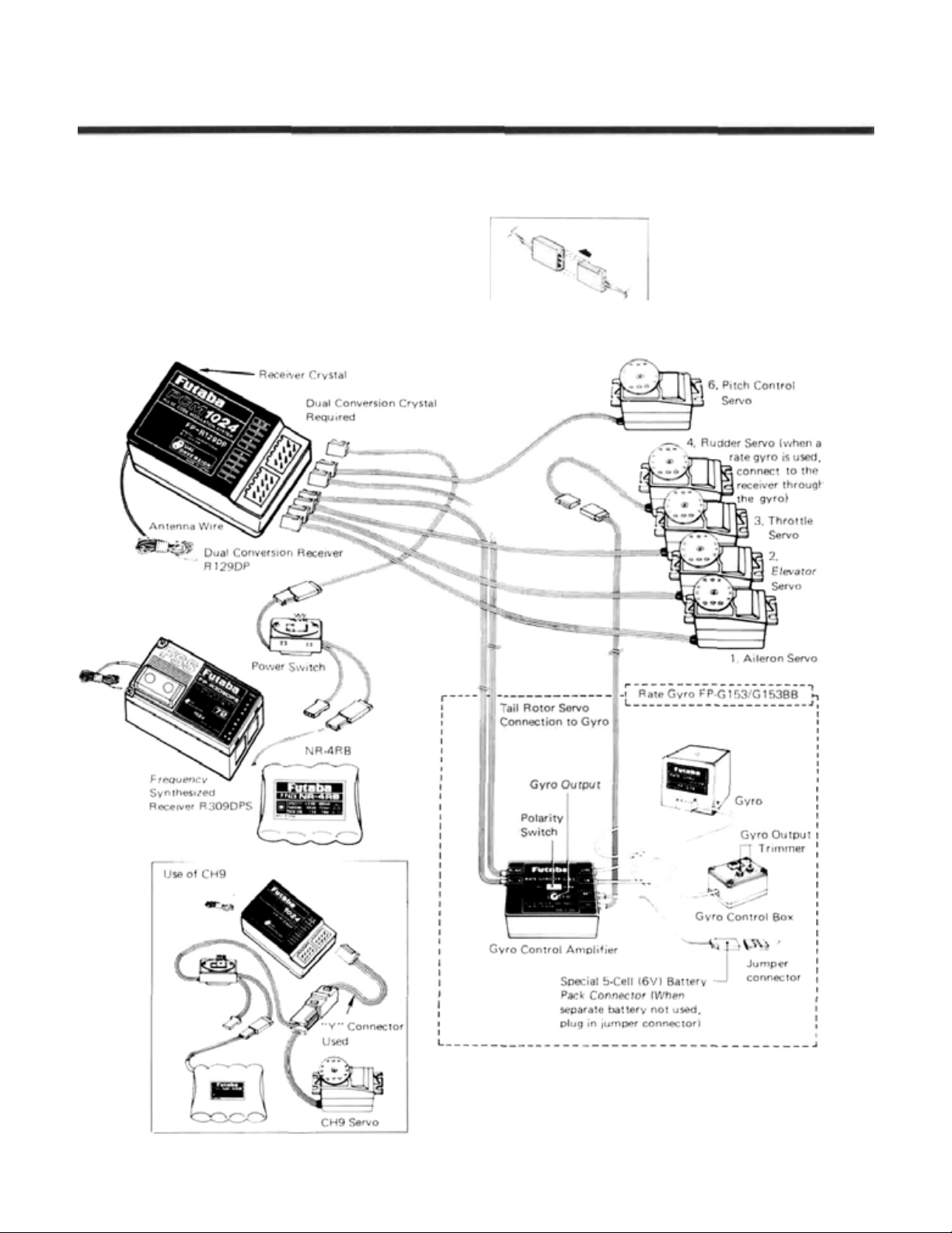
HELICOPTER RECEIVER AMD SERVO CONNECTION
The receiver output order is shown below:
1. AIL Aileron
2. ELE Elevator
3. THR Throttle
4. RUD Rudder
5. GYR Rate Gyro Sensitivity Switching
6. PIT Pitch
7. AU1
8. AU2
9. CH9 Channel 9
(Spare)
(Spare)
Be sure to insert proper
direction
Helicopter Section
Five Servos are supplied
as standard
Helicopter Section, Page 98
Page 23
SAMPLE HELICOPTER SETUP INSTRUCTION
Helicopter Section
The following example shows how the PCM
1024ZH may be programmed for a contest helicopter model, although for completeness we have
added other functions (these will be marked by a
"t" sign). The settings presented here are for a
typical model. Your model's settings are likely to
vary
from
these,
but
the
procedures
given
will
still
be applicable.
1 Memory Selection
Use the Model Select function
model memory.
Choose the Helicopter Setup using the Type
function from Model menu.
2 Model Naming
Name the model using the Model Name
tion in the model menu. Not e that the default flight
condition is named "NORML" (the condition name
is located next to the model name). The system
automatically adds and names three other flight
conditions, which you will program later in this
example.
MSL
to select a
TYP
MNA
func-
5 Plug Servos Into Receiver
Plug Servos into Correct Channel Numbers
1 .. . .AIL. .. .
2 ... .E LE. ... .Elevator
3 .. . .THR . . . .Throttle
4 ... .RUD . . . .Rudder
5 ... .GYR . . . .Rate Gyro Sensitivity
6 ... .PIT .... .Pitch
7 ... .AU1 . . . .(Spare)
8 ... .AU2 . . . .(Spare)
9 .. . .CH9. . . . .Channel 9
6 Set
Servo Throw Direction
Check the proper direction of throw for each
servo. Use Reversing Function
menu to set proper throw directions. Reverse channels as necessary to correct throws. Link the carburetor to the throttle servo so that the carb may be
fully closed to shut off engine.
7 Flight Conditions Switching
You may set up the system to call up more than
one function or switch to a new set of trims or control settings simultaneously by moving a single
switch. This is very convenient f or loading different
flight conditions such as Idle-up 1
IDL2
, and Throttle Hold
normal flight condition. You may change EVERY
parameter between flight modes.
We recommend that you fly the model and adjust
trims and control responses to your liking before
defining another flight condition. Then, as described
below, you will copy the set of adjustments to a new
flight condition (this will maintain all trim settings
between the different conditions), and define the
condition switches that activate them. Each may be
modified for the new desired conditions, and you
may add new functions as necessary.
Use the Condition Select
Model Menu. The four flight conditions listed above
have already been allocated. The position and ON
direction of each flight condition call switch are set
as follows:
.Aileron
HOLD
REV
IDL1
in
addition to the
CSL
button in the
in the Model
, Idle-up
2
3t Set Control Order
If desired, reset the Control Order usi ng the Function Control
may choose what sticks, sliders, and tr ims control
the different functions.
FNC
in the model menu. Here you
4 Hook Up Controls
Hookup the aileron, elevator, throttle, and rudder
servos in accordance with the model's instructions
or plans.
1. Normal. . . .
2. Idle-up
Helicopter Section. Page 99
.Operation when. .
all switches OFF etc.
1 .. . .ON at SW (E ) . .. . .For 540° stall
Center position turns, looping,
. .Used in hovering,
rolling stall turns
Page 24
Helicopter Section
3. Idle-up 2 . . . .ON at SW (E) . . . . .Used fo r rolling
4. Throttle . . . .ON at SW (G) .... .Activate for
Hold Forward position autorotation.
In
4>3>2>D,
means that if the Idle-Up 1 switch is on, and Throttle
hold is turned on, the system will use the Throttle
hold settings.
To set the condition data for each flight condition, be sure that you call the appropriate condition
by turning on the correct switch (as given above).
Read the condition name after the model name to be
sure you are changing the condition you want.
Forward position aerobatics.
the
case
above,
the
with 4 having the highest
flight
condition
priority
priority.
This
8 Normal Flight Programs
Select the Normal flight settings by turning off
all the flight condition switches.
9 Throttle Curve Setting
Call the Throttle Curve
Model Menu. Check to see that it is activated ACT .
Next, move to the condition menu and press
TCV
to get the setting menu. Set the t hrottle curve
to the values shown in the table below:
THA
function from the
is
The following settings assume a semi-symmetrical
rotor blade with no twist. For the pitch curve, the
initial LOW rate is 100% and the HI G H r at e is 100%.
Set the maximum pitch angle in advance. The pitch
angle is -4° to +12°.
When setting the pitch angle, set the hovering
pitch lever and the HIGH side pitch lever to the
center positions. These levers may be activated in
flight to make adjustments. Next, input the data so
that the normal pitch used in hovering becomes
-2.5° to+10° by LOW/HIGH side rate setting.
Although unimportant in calm conditions, the
pitch angle should be set to that the High side pitch
rate is large. This provides high collective sensitivity
to help cope with windy conditions.
Pitch Curve Setting.
Move to the Condition menu, and select the pitch
curve PCV ke y. Set the pitch curve to the follow-
ing values:
Point
Setting (%)
1
9218
The rise at the low end is fast, and then the rise
rate
is reduced at the high end. We recommend
setting the hovering pitch to +4.5°.
27
4
3
5
35
43
6
52759
67
8
97310
11
78 82
11 Flight Condition Copying
Use the Condition Select
Model Menu. This function displays the flight conditions associated with the model in active memory.
Note the condition number next to the D (default)
in the display. This is the set of conditions associated
with the trimmed model. Also note the three num-
bers following: these are the conditions associated
with Idle-up 1&2 and Throttle Hold, that will be
copied into and modified.
CSL
button in the
11
86
13
88
The throttle responds slowly at first and then the
response rate increases at the top end.
10
Pitch Curve Setting
Call the pitch curve PIT function from the
model menu. Verify that the PIT curve function is
activated (
ACT ).
Use the Copy Condition CPC from the System
menu. This function may be used to copy the con-
tents of one condition into another. Choose the
default flight condition number (next to the D),
press the
condition number in the lower box "TO CONDITION." Give the command to copy. Repeat for
Idle-up 2 and Throttle-hold conditions.
Normal->-ldle-up 1
Normal->ldle-up 1
Normal->Throttle Hold
Helicopter Section, Pag e 10 0
SET
button, then choose the Idle-up 1
Page 25

12
Idle-Up 1 Setting
The switch that calls the Idle-up 1 conditions
(SW-E, center position) is not yet activated. In the
Model menu, press the Condition Select
then select the condition position. Press the Switch
button
SWT
selected), and press the center position button ( Q).
Hit the previous key
Move the Idle-up 1 switch to its ON position and
verify that the condition name after the model name
refers to Idle-up 1. Then you may go through the
Condition menu items to revise the desired settings
in the new mode.
Throttle Curve Setting:
and press TCV to get the setting menu. Change the
first seven Idle-up 1 throttle curve points to the
values shown in the table below:
, select SW-E (if it is not already
PRE
and
END
move to the condition menu
CSL
key,
to finish.
Helicopter Section
14
Throttle Hold Setting
Now the Throttle Hold conditions are set for use
in autorotation. Call up the Throttle Hold conditions by setting SW-G to the 1 (forward) position.
Now you will set the Throttle Hold O N /OFF switch
so that SW (G) is turned on in the 1 (forward)
position, the same as th e flight condition call switch:
HLD
Call the Throttle Hold
condition menu. Set the condition switch SW (G) to
the 1 (forward) position. Select the Manual mode
MAN and activate the throttle hold function. Press
the SWT button to get to the Switch menu, and
activate the SW (G)-1 position. Hit
to exit.
function from the
PRE
and
END
Pitch Curve Setting:
key. The Normal curve copied already appears on
the screen. The Idle-up 1 pitch curve uses the same
curve as the normal condition, but the maximum
HIGH side pitch angle should be 8° to 10°, depending on the engine used. Set the pitch angle by curve
or rate.
Idle-Up 2 Setting
13
Call up the Idle-up 2 conditions by setting SW-E
to the 1 (forward) position. Be sure that the switch
is defined using CSL as in the previous case. Now,
you may go through the menu items to revise the
desired settings in the new mode (be sure that the
condition name after the model name refers to Idle-
up 2).
Throttle Curve Setting:
and press TCV to get the setting menu. Change the
first seven Idle-up 2 throttle curve points to the
values shown in the table below:
Pitch Curve Setting: Select the pitch curve
key. The Normal curve copied already appears on
the screen. Set the HIGH side pit c h th e same as Idle-
up 1. Values may be easily compared by switching
between Idle-up 1 & 2 with the condition switch, so
settings may be easily matched. Set the LOW side
pitch curve to the follow ing values:
Select the pitch curve PCV
move to the condition menu
PCV
When SW (G ) is in the 1 (forward) position, the
throttle hold function is turned on and when SW ( G )
is in the 2 (rear) position, the function is turned off.
In throttle hold, set the throttle to move th e servo to
engine idle (approximately 15%).
Pitch Curve Setting:
key. The Normal curve copied already appears on
the screen. During autorotation. maximum pitch is
used at both the HIGH and LOW sides. Therefore,
normally set the HI GH and LOW rates to 100% each.
The curve must be set so th at the r ise matches the
rotor near points 2 to 6. The rotor blade pitch angle
is-4° to+12°.
The pitch angle for each flight condition is shown
below:
.......
Normal
Idle-up 1 ....... -2.5° ~ 4.5° ~ 8°
Idle-up 2
Throttle Hold . .. . -4° ~ 4.5° ~ 12°
15
Pitch-rudder Mix Setting
Pitch->Rudder
to suppress the torque reaction of the main rotor
due to changes in collective pitch. The shape of the
mixing curve may be set independently for each
flight condition.
.......
Select the pitch curve PVC
-2.5° ~ 4.5° ~ 10°
-4° ~ 4.5° ~ 8°
P->R
mixing
uses
the
tail
rotor
Adjust the pitch curve low side to -4°
Helicopter Section, Page 101
Page 26

Helicopter Section
To set this feature, call the Pitch->R udder P->R
from the Condition Menu. The Normal setting is
used during hover, so it should be set to match takeoff, landing, and constant speed vertical climbing.
Normal Setting:
Select the normal flight conditions by turning off
all the flight condition switches. Set th e rudder mi x -
ing curve to the following values (initial settings):
Idle-up 1 Setting:
These settings are used in 540° stall turns, loop-
ing, and rolling stall turns and is set to be straight
ahead when the model is pointing directly into or
away from the wind. Call the Idle-up 1 flight conditions by moving swi tch E to the 0 (center) position.
Set the rudder mixing curve to the following values:
When these values are input, the rudder is offset
at the half-throttle position.
Idle-up 2 Setting:
These settings are used in rolls. Acti vate the Idleup 2 flight conditions by moving switch E to the 1
(forward) position. Set the rudder mixing curve to
the following values:
17 Rudder->Throttle Mix Setting
Rudder->Throttle
hovering eight, nose in circle, top hat, pirouette, an d
other aerobatics. It should be set so that at halfthrottle, if the rudder stick is operated, the rotor
speed is maintained to keep altitude constant.
For normal models, commanding right rudder
should increase throttle slightly, while using left
rudder should decrease throttle slightly.
To set this feature, return to the Normal flight
condition.
the Condition Menu. Press the
vate it, and set the Left value to -10%, and the
Right value to +10%.
Press
R->T
mixing is effective in
the Rudder->Throttle
ACT
button to acti-
18 Trim Offset Setting
The Tri m Offset
ed for Idle-up 1 and Idle-up 2. Aileron, elevator, and
rudder are offset so that the model flies straight
ahead during normal flight.
TOF
setting should be adjust-
R->T
from
The rudder is offset at the half-throttle position.
Throttle Hold Setting:
Throttle Hold settings are intended to keep the
model pointed str a ig ht ahead during linear autorotation. The tail rotor pitch angle is nearly 0°. Set t he
Throttle Hold flight conditions by moving switch G
to the 1 (forward) position. Set the rudder mixing
curve to the following values:
Delay Settings
Set the amount of delay for each flight condi-
tion. We recommend the following settings:
Normal .......
Idle-up 1 .......
Idle-up
2. ......20%
Throttle Hold . . . . 60%
The delay for Throttle hold should be large, because the rudder angle changes significantly during
flight condition changes.
20%
20%
Helicopter Section, Page 102
Call the Idle-up 1 or 2 flight condition by setting
Switch E to the 0 (center) position. Press the TOF
button from the Condition menu. Recommended
settings for aileron and elevator offsets are 6% to
10%. A delay can be set with the digital trim
function.
Rudder offset is set by the Pitch->Rudder func-
tion set previously, so is not set here.
TRM
Page 27

Helicopter Section
19
Gyro Sensitivity Switching
Gyro Sensitivity switching may be set for each
flight condition. To set sensitivity, call the Gyro
Sensitivity Function
menu.
Assuming that the sensitivity o f the gyro is set so
that the 1 side was made low sensitivity, and the 2
side was defined as high sensitivity, set the type at
each flight condition as follows:
.......
Normal
Idle-up
1
Idle-up 2
Autorotation .... Type 1 (i f the tail rotor is
.......
.......
GYR
Type 2
Type
Type 1
from the condition
1
driven during autorotation, high gyro
sensitivity (type 2)
may be more effective.)
20 Engine Cut Setting
At the conclusion of a flight, you may use the
Engine Cut function to kill your engine by one
touch with a special switch. Because it is performed
by stick lever, there is no need to fumble for the
trim position, and the idle trim position need never
be lost.
Press the Engine Cut
model menu, activate it, and set the desired switch.
Set the throttle a bit above t he lowest throttle position, then press the
position. This makes it so the engine cut function
will only operate when the throttle is at the idle
position, so the engine can't inadvertently be shut
off.
Adjust the throttle servo motion so that there is
no binding or excess travel.
CUT
button from the
SET
button to memorize the
21 Condition Hold Setting
If you want to set condition data while the
engine is running, always use the Condition Hold
function
Press the CHD button on the Model menu. Set the
maximum throttle position to be a bit above the idle
position, and press the
produce a maximum throttle setting of about 13%.
Be sure not to set the maximum too high.
the Home menu (use the G key), from the Model
menu (2nd line, G key), or from the Condition
menu (use theMkey). When Condition Hold is
activated, a double beep repeats every few seconds
to remind you that it is engaged, so that you do not
attempt to f ly with it on. This setting allows you to
control the throttle between 0% and 13% with the
throttle stick when the function is activated.
sure to browse through the pages following this
example to see what other menus are available for
helicopters, such as
INV
bilities or to correct bad tendencies. All of these
menus may have different settings in different flight
modes. For this reason, we recommend you set them
up and use them in the Normal flig ht condition and
trim the model before setting up the alternate flight
modes.
CHD
to limit the throttle operation range.
SET
key. This should
You may activate the Condition Hold menu from
This concludes the setup procedure example. Be
. Many may be used to enhance flight capa-
HOF . GYR , ACC ,
and
Helicopter Section, Page 103
Page 28

Helicopter Section
PITCH CURVE
This function may be used to set different pitch
response curves for each flight condition (normal,
idle-up 1, idle-up 2, throttle hold, etc.). This func-
tion
is
activated
tion
is
selected.
A 13-point curve can be input, and Point 7 can
Setting Up Pitch Mixing
Pitch Curve Inputting
In the Condition Menu, press the PCV key to get the
PIT CURVE menu shown below.
Curve setting-
Rate
setting
High side-
Low side-
when
(PCV)
the
respective
flight
condi-
be defined as the pitch curve reference point. You
may
also
define
volumes
defined as the right side lever at initial setting).
Pitch curve activation should be done with the
model menu pitch curve (PIT) function (page 58).
(the
High
high-side
and
pitch
low
side
trim
volume
Point Movement
Buttons
Trim volume setting
rate
control
trim
is
Setting Point Selection (Points 1 to 13)
Press the B key to turn on the curve inputting
function. Use the movement keysQand R to select the
point whose value is to be set. The
the point number by one, and the <-PT key reduces the
point number by one. The active point on the curve Is
shown as a black dot.
Curve Point Rate Setting
Once you have selected the desired point on the curve,
you may input the rate with the rate setting keys
M The number keys 0 through
directly. The + and - keys increase or decrease the
value by 0.5 with each button pressing (so it takes two
hits to see a number change because of numeric rounding).
You may set or reset each point on the curve by
repeating these steps for each point.
High-Side Rate Adjustment
Press the C key to adjust the High-Side rates. The
numeric keys E to M are used to directly set the rate,
which may vary from 0 to 110%. The default value is
100%.
PT->
key increases
100
input the value
E
Return to
Condition Menu
Low-Side Rate Adjustment
You may set the Low-Side rates by pressing the D
key. As before, the rate may be set with the numeric keys
E to M. This r ate may var y from 0 to 110%, and its
default value is 100%.
Trim Volume Setting
If you'd like to be able to change the pitch curve while
in flight, you can set up this feature in the volume setting
screen. Press the O key to get into this screen, and
to
choose the control you'd like to use for this feature. For
a description of the volume setting method, see page 37).
The right slider is set as the high side trim volume when
Pitch Curve is activated.
Note: when Point 7 of the pitch curve is changed
after setting the HIGH/LOW side rates, the other points
change also. This is because Point 7 is used as the rate
setting reference point.
Helicopter Section, Page 104
Page 29

HOVERING PITCH (PHV)
This function trims the pitch near the hovering
point. By setting a range, adjustment is possible
without changing the high and low points. This
Hovering pitch setting can be made for each flight
condition,
condition.
trols hovering pitch volume.
Activation of command
PIT HOVER menu shown below. Use the A key to
activate mode setting, then press the ACT or INH
keys ( F and G) to activate or inhibit the function.
but
is
commonly
At initial definition, the left sliding lever con-
In the Condition Menu, press t he
used
for
PHV
Normal
flight
key to get the
Helicopter Section
Mode setting
Trim deflection
setting
Range setting
Rate setting
Mode selection
Hovering Pitch Trim Deflection Setting
Press theBkey to allow input to this setting, and
input the rate with the numeric keys F to M . The
deflection may be set fr om 0 t o 100% ( the initial value of
this parameter is defined to be 100%).
Setting of Range
Now you will set the Range of travel over which
HIGH/LOW
the
be set from 0 to 100% (when activated, the initial value of
this parameter is defined to be 100%).
Offset Rate Setting
and
input from -100 to +100%, and the initial value is
programmed to 0%.
sides
do
not
change.
rate
with
the numeric
The offset amount is entered by pressing the D key,
input
with
the numeric
Press
the
Ckey
keys F to M. The
keys E to M. Thi s may be
Range
and
may
set
Hovering Throttle
trim volume setting
• Return to
Condition
screen
Hovering Pitch Trim Selection and Operation Direction
Setting
Call up the volume setting screen by pressing the
VOL O
key. Set the volume control as desired (the
left-side slider is set as the pitch trim volume control
initially). For a description of the volume setting method,
see page 37).
Precautions
When the range is set to 100%. the rate changes between points 1 and 13. When the range is set to 0%, the
rate changes on ly between points 6 and 8. When you use
this function, set up t he numbers so that when the range
is small, the trim deflection is also small, and make sure
that the preceding and following points are not exceeded
when the range is moved to its maximum position.
Helicopter Section, Page 105
Page 30

PITCH TRIM (PTM)
Helicopter Section
This function enables you to move the pitch
trim (offset the trim) without changing the pitch
curve. The amount of pitch tri m can be adjusted,
and may change for each condition.
At initial setting, the left side knob VR(A) is
defined as the pitch trim volume control. However, the knob is not activated at initial setting.
Activation of command
In the Condition Menu, press the
PITCH TRIM menu shown below. Use the A ke y
to
activate
keys (F and
Mode setting
Pitch Trim Rate
Adjustment
mode
setting,
then
G)
to activate or inhibit the function.
press
PTM
the
key to get the
ACTorINH
Servo
Pitch Trim
Rate
Stick
Position
Pitch trim
Volume setting
to
Return
Condition
screen
Mode selection
Rate
setting
Press the B to input the rate to be set with the
numeric keys F to M . The rate setting may range fr om
0 to 100%. and is initially programmed as 30%.
Volume selection
Enter the volume setting
key. For a description of the volume setting method, see
page 37. The left side knob is set as the volume control at
initial setting, but is not activated. Be sure that you are
setting for the desired condition by first turning on the
condition switch and verifying the condition name.
screen
by
pressing
theO
Helicopter Section, Page 106
Page 31

Helicopter Section
THROTTLE CURVE
This function programs throttle curves to perform hovering, loops, rolls, and other aerobatics in
the
different
the
servo
Setting Up The Throttle Curve Function
Throttle Curve Inputting
In the Condition Menu, press t he
THR CURVE menu shown in the upper portion of the
figure below.
Curve setting
Low Side
Rate Setting
flight
response
modes.
over
The
the
full
(TCV)
throttle
stroke
•TCV
key to get the
curve sets
of
the
throttle
rate can be input (point 7 is the reference). The
servo
switching can be programmed.
stick
delay
by a 13-point
at
idle-up
and
curve.
other
The
low
flight
condition
Point Movement
To Next Screen
Return To
Condition Menu
side
Delay Amount
Setting
Setting Point Selection (Points 1 to 13)
Press the B key to turn on the curve inputting
function. Use the movement keys
point whose value is to be set. The
the point number by one, and the
point number by one. The active point on the curve is
shown as a black dot.
Once you have selected the desired point on the curve,
you may input the rate with the rate setting keys
M . The number keys 0 through
directly. The + and - keys increase or decrease the
value by 0.5 with each button pressing (so it takes two
hits to see a number change because of numeric rounding).
You may set or reset each point on the curve by
repeating these steps for each point.
Q
and R to select the
PT->
key increases
<-PT
key reduces the
100
input the value
E
Low-Side Rate Adjustment
Press
the D key and
numeric keys
range from 0 to 110% (initially the rate is set to 100%).
Delay setting
Shift to the next screen (the lower one in the figure)
by pressing the
rate setting keys E to M. The delay may be set from 0
to
to 100%, and is in itially set to 0%.
Use the END ( N) key to leave this menu.
you
may
E to M.
You may set anywhere in the
NXT (P)
input
key. Enter the delay with the
To Preceding
Screen
the rate
with
the
Helicopter Section, Page 107
Page 32

HOVERING THROTTLE (THV)
Helicopter Section
This
function
around is hovering position. By setting a range,
adjustment is possible without changing the high
and low points. This Hovering throttle setting can
be changed between the flight conditions, and
ACT/INH may be set separately for each.
At initial definition, the right knob VR(B)
controls hovering throttle t ri m .
Activation of command
In the Condition Menu, press the
THR HOVER menu shown below. Use the A key
to activate mode setting, then press the
keys F and G) to activate or inhibit the function.
Mode setting
Trim Deflection
Width Setting
Range setting
Rate setting
is
used
to
trim
the
THV
throttle
key to get the
ACTorINH
Servo
Servo
Stick Stick
Hovering Pitch
trim volume setting
Return to
Condition Menu
Mode selection Actual Value, Including Volume Adjustment
Hovering Throttle Trim Deflection Setting
Press the B key to allow input to this setting, and
input the rate with the numeric keys F to M. The
deflection may be set from 0 to 100% ( whe n activated,
the initial value if this parameter is defined at 100%).
Setting of Range
Now you will set the Range of travel over which
HIGH/LOW sides do not change. Press the C key and set
the rate with the numeric keys
be set from 0 to 100% (when activated, the initial value if
this parameter is defined at 100%).
F to M.
The range may
Offset Rate Setting
The offset amount is entered by pressing the D key,
and input with the numeric keys
input from -100 to +100%, and the initial value is
programmed to 0%.
Hovering Throttle Trim Selection and Operation Direction
Setting
Call up the volume setting screen by pressing the
VOL O
key. Set the volume control as desired (the
right-side knob VR(B) is set as the pitch trim volume
control initially). For a description of the volume setting
method, see page 37).
E to M.
This may be
Helicopter Section, Pag e 108
Page 33

HOVERING OFFSET (HOF)
Helicopter Section
This function is used to program the pitch mixing hovering point. It is used to set the HIGH/
LOW side switching point to the pitch hovering
point when the pitch hovering point has drifted
Activation of command
In the Condition Menu, press the
HOV OFFSET menu shown below.
Offset setting
HOF
key to get the
"HOV" appears when the stick is at hovering point
Rate setting keys
above or below the stick neutral position. The
model should be adjusted so that hovering is performed around the mid-throttle position.
Return to
condition menu
Setting Method
Offset setting
During flight, make a note of where the throttle stick
is positioned during hover. Set the throttle stick to the
hovering position and adjust the offset with the F and
G keys until "HOV" is displayed on the screen. This
function has a range of -30 to +30%, and its initial value
is0%.
Helicopter Section, Page 109
Page 34

Helicopter Section
THROTTLE HOLD
This function moves the throttle servo to idle
during auto rotation. Either a Manual mode or an
Auto mode can be selected. In the manual mode,
the throttle servo is held by turning on the throttle
hold switch. In the auto mode, the throttle servo is
held when the throttle stick is moved past the set
Activation of command
In the Condition Menu, press the HLD key to get the
THR HOLD menu shown below.
Mode setting
Hold Position
Setting
Delay setting
(HLD)
position
hold switch is turned on.
set. Throttle trim can be turned on and off during
throttle hold, but it is usually turned on.
on
the
low
throttle
A delay up to the servo hold position can be
side
after
the
throttle
Throttle Trim
ON/OFF
ON/OFF
Switch Setting
Trim Volume
Setting
Return to
condition menu
Mode selection
Select Operation Mode
Use the A key to activate mode setting. Now
you must decide on Manual or Auto operation.
Select the manual mode by pressing the MAN (G)
AUT
B
key, then
( H)
SWT
see
key. Select the auto mode by pressing the
key. You
(INH)
Throttle hold ON/OFF switch setting
trol switch. You may choose another switch with this
menu. For a description of the switch setting method,
page 37 .
Stick Position Setting (Auto Mode Only)
which the function will take effect. Press the
move the throttle stick to the desired position, and press
the
throttle stick is near half-throttle position for hovering,
this should be around 20% throttle position.
may
deactivate the function by
key.
Call the switch setting screen by pressing the
(P
) key. At initial setting. SW (G) is defined as the con-
For the Auto mode, you need t o input the position at
SET
(F) key to memorize the position. If the
pressing the F
Servo Hold Position Setting
Press the C key and set the Idling position with the
rate setting keys
to 100%, and is initially set to 15% by the system. At the
set position, the carburetor should be fully closed.
Delay setting
Press
the D key and
keys F to M . The setting range is 0 to 100%, and the
initial value loaded is 0%.
Throttle trim ON/OFF at throttle hold
Press
the R key to
menu. The function may be activated by pressing the
ACT
( F) key, and deactivated by pressing the
(G) key.
Servo Hold Position Trim Volume Selection and Operat-
ing Direction Setting
You may set a control to adjust the trim volume
during flight. For a description of the volume setting
method, see page 37. This volume is not loaded at initial
setting, but may be adjusted ±10% by the volume control.
F to M .
set
enter
This setting may vary from 0
the delay
with
the throttle
the
trim
rate setting
activation
INH
Helicopter Section, Page 110
Page 35

Helicopter Section
SWASHPLATE TYPE
The SWP function has two built-in functions:
Swash--Throttle mixing, and Swash rotation.
These functions can be set for each flight condition.
Swash->Throttle
tendency of the model to change altitude when
Using the Swashplate Menu
In the Condition Menu. press the
SWASH PAR menu shown below.
mixing
(SWP)
is
used
SWP
to
correct
key to get the
the
the rotor is tilted by aileron, elevator, and other
controls. The Swash Rotation function is used
when the swash plate connections are shifted a
fixed angle from the reference position.
Mode setting
Mixing rate
setting
Mode setting
Angle setting
Return to
condition menu
Swash
throttle
mixing
Swash
rotation
Mode selection
Activation of Swash-Throttle Mixing command
Use the R key to activate mode setting, then press the
ACT
or
INH
keys ( F and G ) to activate or inhibit
the aileron differential function.
Swash-Throttle Mixing Rate Setting
Press theQkey and enter the desired mixing rate
with the rate setting numeric keys
be set from 0 to 100%; the system enters an initial value
of 50%.
F to M.
Mixing may
Swash Rotation Setting
Press
the P to turn the
on. You may activate the offset mixing by pressing the
ACT (F) key, and deactivate by pressing the INH
(G) key.
Swash Rotation Angle Inputting
Press
the O
setting numeric keys
anywhere between -30° to +30°, and its initial value is
set
to
0°.
key
and
E to M .
swash
rotation
set
the
angle
with
This value may be set
setting menu
the
angle
Helicopter Section, Page 11 1
Page 36

PiTCH-RuDDER (P-R)
Helicopter Section
This mixing, also called Revolution Mix. mixes
pitch commands into rudder in order to suppress
the torque generated by changes in the main
rotor's pitch angle. A five-poin t curve can be used
to control the shape of the mixing curve for each
Setting Up Pitch->Rudder Mixing
Pitch Mixing Activation
In the Condition Menu, press the
PIT TO RUD menu shown below.
Mode selection
Curve setting
UP side rate setting
DOWN side
rate setting
P-R
key to get the
Mode setting Set value, including volume adjustment.
flight condition. The up-side and down-side mixing
rates can be set, using Point 0 as the reference. A
trim volume can be input f or each direction, and a
time delay to transition smoothly between flight
conditions may also be set.
Point movement
keys
To delay setting
screen
Trim volume
setting
Return to
condition menu
Use the A key to activate mode setting, then
press the
or inhibit the function.
Setting Points -2, -1, 0, +1, +2
Press
function. Use the movement keys Q and R to select the
point whose value is to be set. The
the point number by one, and the
point number by one. The active point on the curve is
shown as a black dot.
Once y ou have selected the desired point on the curve,
you may input the rate with the rate setting keys E to
M
. The number keys 0 through
directly. The + and - keys increase or decrease the
value by 0.5 with each button pressing (so it takes two
hits to see a number change because of numeric rounding). The +/- key changes the sign of the entered
number.
You may set or reset each point on the curve by
repeating these steps fo r each point.
Up-Side Rate Adjustment
Press
numeric keys
range from 0 to 100% (initially the rate is set to 100%).
ACT
or
INH
keys F and G) to activate
the B key
the C key and you may
to
E to M .
turn on the
You may set anywhere in the
curve
input
inputting
PT->
key increases
<-PT
key reduces the
100
input the value
the
rate
with
the
Down-Side Rate Adjustment
Press the D key and you may input the rat e with the
numeric keys
range from 0 to 100% (initially the rate is set to 100%).
Up & Down Sides Trim Volume se l ection
Enter the volume setting screen by pressing the O
key. For a description of the volume setting method, see
page 37. The volume control has an adjustment range of
±25% of the rates input above. No control is set as the
volume control at initial setting. Be sure that you are
setting the desired condition by verifying the condition
name.
Delay set tin g
Call
( P ) key. Now press the key and set the delay with
the rate setting keys E to
100%, and t he i ni t ia l v alu e loaded is 0%.
E to M .
the delay setting
You may set anywhere in the
screen
by
pressing the NXT
M
. The setting range is 0 to
Helicopter Section, Page 112
Page 37

Helicopter Section
RUDDER->THROTTLE
This mixing adjusts the throttle setting to
account for the changes in power required when
rudder commands are made. The amount of mix ing can be set for each condition, and the left and
right
rates
may
be
set
separately.
may also be set.
Setting Up Rudders-Throttle Mixing
In the Condition Menu, press the
RUD TO THR menu shown below.
Mode setting
Left side rate
Setting
Right side rate
setting
(R->T)
Trim
R->T
volumes
key to get the
Trim Volume
Setting
Return to
condition menu
Mode selection Set value, including volume adjustment
Activation of Rudder-Throttle Mixing command
Use the A key to activate mode setting, then press the
ACT
or
INH
the Rudder-Throttle function.
Left-Side Rate Adjustment
Press
numeric keys E to M . You may set anywhere in the
range from -50 to +50% (i n it ia ll y the r ate is set to +25%,
but a rate between 0 and 20% is recommended). Use the
+/- key to change the sign if necessary.
keys ( F and G) to activate or inhibit
the C
key
and you
may
input
the rate
with
the
Right-Side Rate Adjustment
Press
the D key and you
numeric keys E to M . You may set anywhere in the
range fro m -50 t o +50% ( in it ia ll y the rate is set to +25%;
again a rate from 0-20% is recommended).
Trim Volume Selection and Operating Direction Setting
You may set a control to adjust the trim volume
during
flight.
Call
VOL ( O
adjusting method,
by the volume control.
the volume
) key. For a description of the volume
may
input the
setting
screen
see
page
37. This volume may b e adjusted
rate
with
by
the
pressing
Helicopter Section, Page 113
Page 38

Helicopter Section
GYRO SENSITIVITY
This function switches the gyro sensitivity. T he
mode depends on the gyro used. Usually,
vity 1 or 2 is
The Normal mode is used with gyros having
two-step switching. The sensitivity is pre-adjusted
at two values and is selected by means of this
function.
The Linear mode is used with gyros whose
sensitivity can be switched linearly. The sensitivity
can be lowered according to the rudder travel by
means of this function.
An
EXP
sensitivity remains constant (maximum sensitivity)
up to the point at which gyro sensitivity is suppressed according to rudder operation. However,
the maximum and minimum sensitivities are set at
the gyro.
Using the G yro Sensitivity Menu
In the Condition Menu. press the
G YR O SENSE menu shown below.
switched in the normal mode.
mixing
curve
may
(GYR)
also
be
input.
GYR
key to get the
sensiti-
The
Linear Mode
Position 0%
Gyr o Sensitivity
Position 100%
Gyro Sensitivity
100%
100%
Mode setting
Sensitivity No.
Selection
Mode setting
Rudder stick
position setting
EXP rate setting
Return to
condition menu
Mode selection
Helicopter Section, Page 114
Page 39

Select the Gyro Mode
Press the
Select the normal mode by pressing the
Select the linear mode by pressing the
Deactivate the function by pressing the
A
key to enter the mode selection menu.
NOR ( F )
LIN ( G )
INH ( H )
Helicopter Section
key.
key.
key.
Normal mode
Select the sensitivity number by
pressing the F ( 1 ) or G ( 2 )
key.
Press th e
E ND (N) key to exit this menu.
Linear mode
Set Rudder Stick Position
Press the C key and set the rudder stick position with the numeric keys
F to M.
You may input from 0 to
numeric keys input the number; ( + ) and ( - ) change the inputted value by
+/- 1, and t h e +/- key changes the sign.
Set EX P rate
Press
the D key and set
The numeric keys work the same as given in the previous paragraph.
the
curve rate
100%
(initially
with
the numeric
50%
is
entered). The
k ey s F to M.
Helicopter Section, Page 115
Page 40

Helicopter Section
ACCELERATION
This mixing function is used to cancel the reaction torque generated by sudden throttle
changes. The amount of mixing and the rudder
servo return delay can both be programmed.
Using the Acceleration Function
In the Condition Menu, press the
AC CE LE R menu shown below.
Mode setting
Mixing rate setting
Delay setting
(ACC)
ACC
key to get the
• Return to
Condition Menu
Mode selection
Activation of Acceleration Command Delay setting
Use theAkey to activate mode setting, then press the Call the delay setting screen by pressing the 0 key.
ACTorINH
the Acceleration function. The setting range is 0 to 100%. and the initial value loaded
Mixing rate setting
To input the mixing rate, press the C key and set the Exiting
mixing rate wi th the rate setting keys F to M. The mix - To exit the Acceleration Mix function, use the
ing rate is initially set to a value of 50%, but may be set N key.
from 0 to 100% using the numeric keys.
keys
(F and G)
to
activate or
inhibit
Now
set
the delay with the
is
50%.
rate
setting
keys F to M.
END
Helicopter Section, Page 116
Page 41

Helicopter Section
INVERTED PITCH
This
function
side and low-side rates during inverted flight. All
linkages should be set up for inverted flight. In-
verted flight function activation and cross position
setting are performed with the Inverted Pitch
(INV) function in the model menu (pag e 57).
Setting Up The Inverted Pitch Function
In the Condition Menu,
INV PITCH menu shown below.
High side
pitch setting
Low side pitch
setting
sets
the
press
(INV)
inverted
the INH key
pitch
to
get
high-
the
Return to
condition
menu
Numeric keys
Inverted Flight High Pitch Rate Setting
Press the C key and you may input the rate with the
numeric keys F to M . You may set anywhere in the
range fro m 0 to 110% (initially the rate is set to 100%).
Inverted Flight Low Pitch Rate Adjustment
Press
the D
key
and
you
may
input
the rate
with
the
numeric keys F to M. You may set anywhere in the
range from 0 to 100% (initially the rate is set to 100%).
Exiting
To exit the Acceleration Mix function, use the
N
key.
END
Helicopter Section, Page 117
Page 42

SAILPLANE SECTION
This section contains information on the commands that apply to
sailplanes only. Each o f these functions can be se t independently for
different flight conditions. The sailplane model types are grouped
into
2-S
type,
4-S
type,
and
5-S
type
by
number
wing. The Condition menus for these three sailplane types are shown
on the next page.
In this manual, speed flaps are controls that can move together
(as flaps) or differentially (as ailerons), and are commonly found on
most high-performance models. Brake flaps move together only, and
are used for landing. Brake flaps are sometimes found on scale
models. Butterfly is a high drag configuration used for landings,
referred
and would l ike to h ave a three position switch on the left-hand side,
we recommend you purchase a Mode I airplane radio (and convert
to Mode II) or a Mode II helicopter radio.
STM, TOF, CNA, and TRM functions), refer to the Common Conditions section. For instructions on Helicopters and Airplanes, refer
to
Sailplane
Sailplane Transmitter Controls and Functions. ................
Sailplane
Sailplane
Control
ADF .... .Aileron Differential. ..... .Sets different aileron up ... 125
A-R
ASF. .... .Aileron-» Speed flap . .... .Increased roll authority for . 127
VTL
ABE .... .Air Brake-> Elevator. . . .. .Trims pitch change due. ... 129
EBF.
ESP. .... .
BKF
SPF
SFT.
BFY
BYE
ETM . . . . .Elevator Trim (2-S/5-S) . . . .Elevator Presets for flight . . 143
TM1&2.. .
P-»E
E-»F
PPN.
to
as
"Crow"
If you plan to use the PCM 1024Z system primarily for sailplanes
For conditions that apply to all models (ATV, AFR, D/R, PMX,
the sections pertaining to those aircraft.
Section
Receiver and
Setup Example.
Setup
Definitions_________________________________
(2-S/4-S/5-S) & down throws
....
.Aileron->
(2-S/4-S/5-S) coordinated turns
(4-S/5-S) 4-S & 5-S
....
.V-Tail.
....
.....
....
....
(2-S/4-S/5-S) to airbrakes
.Elevator-<•
(5-S)
E I evator-- Speed Flap
(4-S)
....
.Brake
.Speed Flap
....
.Speed Flap
(4-S/5-S) camber on 4-S & 5-S
....
.Butterfly
.Butterfly-> Elevator
(4-S/5-S) butterfly trim change
.Trim
.... .Flap-» Elevator (2-S). .. .. .Corrects tri m change . .... 147
.Elevator-> Flap
....
.Flaperon
elsewhere.
Table
of
Contents___________________________
Servo
Connections.
............................
Rudder.
.............
turning capability, 5-S
Flap
Mix 1 & 2 (4-S)
(2-S).
Brake
(5-S) .
(4-S)
Trim
(4-S/5-S)
(2-S).
........
......
Flap
.......
.......
.......
......
.....
..................
.Mixing for low-drag,
.Mixes rudder & elevator
for V tail
....
.High
lift
. . . . .High lift for better ......
turning capability, 4-S
.Special
.Special flap mixing
.Compensates for
.....
....
.High
flap mixing
functions, 5- S
functions, 4-S
.Use
to
.High drag for predictable. . .
landings
conditions
.Two
presets
different flight conditions
due to flap motion
lift
turning, 2 -S
.Combined flap & aileron. . .
functions, 2-S
Sailplane Section, Page
for better
change
for
for better
of
servos
.....
. . . 128
......
......
......
wing . .....
.......
........
......
in
118
the
120
121
122
126
130
132
135
139
140
142
145
148
149
Sailplane Section
131
Page 43

SAILPLANE CONDITION MENUS
Five Servo Type (5-S)
Line
Selection
Keys
Function Selection Keys
Four Servo Type (4-S)
Sailplane Section
To Home Screen
To System Menu
To Model Menu
To condition hold menu
Two Servo Type (2-S)
MDL
To get to these settings, press the
menu in an Sai lpla ne setup. To select one, first select the
line containing the desired function with the B , C , or
D keys. Then use the F to L keys to select the function
to be entered.
key from any
Sailplane Section, Page 119
Page 44

SAILPLANE TRANSMITTER CONTROLS AND FUNCTIONS
Functions and locations given in this drawing are
the factory default positions. Each setting can be
easily changed as the owner des ir e s. The Function
Change menu [FNC] may be used for this purpose.
Sailplane Section
Sail plane Section, Page 120
Page 45

SAILPLANE RECEIVER AMD SERVO CONNECTIONS
Sailplane Section
The order for connecting the servos depends on
the
selected
fi ve wing servos). When dual aileron or fla p servos
number
of
wing
servos
(two,
four,
or
are not required, the receiver output channels are
available for other uses. V-tail connections = *
The receiver output order is shown below:
Sailplane Section, Page 121
Page 46

EXAMPLE SAILPLANE SETUP INSTRUCTIONS
Sailplane Section
The following example shows how the PCM
1024Z
may be programmed
for a sailplanes
with
two, four, or five wing servos. The settings present-
ed here are for typical models of the three types.
Your model's settings are likely to vary somewhat
from
these,
but
the procedures
given
will
still be
applicable. To make things easier, be sure that the
horns and linkages are all at the same angles and of
the
same
length.
This
will
make
it
so
identical
servo motion produces identical control surface
movement on both sides.
This manual refers to ailerons, speed flaps, and
brake flaps. Here are the definitions of each:
Ailerons are control surfaces located nearest the
tips of the sailplane's wings. Speed flaps are controls that can move together (as flaps) or differentially (as ailerons), and are commonly found on
most hi gh-performance models. Brake flaps move
together only, and are used for landing. Brake
fla ps are sometimes found on scale models. Additionally,
any
sailplane
can
have
spoilers, and e lectr ics will of course have a motor
control.
Use the Model Select
1
function MSL to select
a vac an t model memory,
and choose desired
sailplane type using the
Type TYP function
from Model menu.
Be sure to select a vacant memory. Choose the default flight condition (we recommend NORML).
2
desired sailplane type. RENAME model now using Later you may add Launch, Speed, Distance, Landing,
the Model Name MNA function in the model menu. etc. (Step 16).
Switch to the Condition menu CND and name the
Set Control Order using
3
the Function Control
FNC in the model
menu. Here you may
choose what sticks and
sliders control the
different functions.
Two Wing Servos
[2-S]
Flaperons, Delta Wing,
Electrics.
Optional airbrakes or
spoilers
Set Flaperon FPN
(recommended). Aileron
differential ADF
doesn't allow Flaperon
mixing. You can get
differential in FPN by
setting endpoints.
Four Wing Servos
[4-S]
F3B, multitask, scale.
Optional airbrakes or
spoilers
To get Butterfly control on the throttle stick, change
the SF2 control to J3.
If you will want full-span camber changing, assign
SF1 to LS (for left slider control) or whatever device
you want (LS is the default). Be sure to cut its
authority down in all flight modes usi ng AFR; around
10% is plenty for most models. Check direction of
travel.
Five Wing Servos
Multitask or Scale with
Optional Airbrakes and/or
spoilers
airbrakes
[5-S]
or
Sailplane Section, Page 122
Page 47

Sailplane Section
Instruction
4
Set V-Tail (i f needed).
2-S
4-S
Choose motor control channel fro m spares (if used).
Plug Servos into Correct
5
Channel Numbers
* = V-Tail outputs
Unnumbered receiver
outputs are spares.
Use Reversing Function REV in the Model menu to necesary to correct throws.
6
Ch 1 =
Ail
1
Ch 2 = Elevator*
Ch 3 = Airbrake
Ch 4 = Rudder*
Ch
5=
Ail
2 (in FLP
mode)
Ch
7=
Ail
2 (in
mode)
DIF
Ch 1 =
Ail
1
Ch 2 = Elevator*
Ch 3 = Airbrake
Ch 4= Rudder*
Ch 5= Flap 1
Ch6= Flap 2
Ch
7=
Ail
2
Ch 1 =
Ail
Ch 2 = Elevator*
Ch 3= Airbrake
Ch 4 = Rudder*
Ch5=Flap1
Ch 6= Flap 2
7 = Ail
Ch
=
Ch 8
Brake flap
set proper throw directions. Reverse channels as
7
If you will use multiple flight modes, choose and set Typically down is used f o r launch presets, and up is
switch for default flight mode. We recommend using used for speed presets. These conditions are set in
the center position of the 3-position switch E. step 16.
8
Set Aileron Differential ADF . More up (reflex) Approximately 2:1 up:down ratio is a good starting
than
down
helps make coordinated
9
Set Aileron->Rudder coupling A->R if desired. Only Little or no coupling is needed for high speeds. Use
low-drag
turns,
point.
At
high
speeds
less
or none
is
needed.
a small percentage is needed, around 10—15%. This the switch SWT command to define the ON position
reduces drag of fuselage yawing to make low-drag of SW-E.
turns. Be sure that rudder moves in correct direction.
10
Glide path control
activation. Set these up
for steeper descent and
more precise landings.
11
Couple Flaps to elevator
for tighter pylon turns
("Nobler" mix ing).
Most models don't need
much (1/16"-1/8"at
wing trailing edge)
Set fla p travel (usually
as much as you can get
and still have roll
control). Spoilers will
help steepen approach.
Set Elev->Flap E->F
Set Butterfly BFY .
Be sure Aileron go up
equal amounts, speed
flaps go down equal
amounts. Lots of flap
(90°) is better.
Set Elev->Speed Flap
ESF mixing.
Add
Speed Flap->Aileron
Mixing SPF at 100%
for uniform wing camber
Set Butterfly BFY .
Be sure Ailerons go up
equal amounts. Brake
Flaps may be coupled to
speed flaps BKF tor
more drag.
Set Elev->Brake Flap
EBF mixing.
Brake Flaps may be
coupled to speed flaps
using
BKF
capability if desired.
change.
Faster roll rate mixing
12
(have the speed flaps
move as ailerons)
Trim inboard flaps
13
—
Aileron->Speed Flap
mixing ASF.
Suggest 50% for
thermalling, 80 - 100% for
speed.
Aileron->Speed Flap
mixing ASF .
Suggest 50% for
thermalling, 80-100% for
speed.
Set speed fl ap trim SFT— . Th is might be used for
landing or cruise preset posit ons.
Switchable elevator trim
14
(make small changes)
Set Throw Volumes ATV to prevent binding. Check each servo at each extreme of motion in all flight modes.
15
Set Elev trim offset
ETM
for different flight
conditions.
~~
Set Elev trim offset
ETM for different flight
conditions.
5-S
1
2
fo r more
lift
Sailplane Section, Page 123
Page 48

Sailplane Section
Instruction 2-S 4-S 5-S
After a few flights to trim the model, you may set you may go through the Condition menu items to
16
different flight modes. You may trim for launch flap/ get the desired settings in the new mode. Read the
aileron droop, speed camber reflex, or other desired condition name after the model name to be sure you
flight modes. You can have different subtrims, rudder are changing the condition you want.
coupling, differential, aileron/speed flap mixing. In Now, you may go through the Condition menu items
fact you may change EVERY parameter between (i.e. ADF, A->R, etc.) to get the desired settings in
fli ght modes, the new mode. Read the condition name after the
Use the Condition Select CSL button in the Model model name to be sure you are changing the condition
Menu. This function allocates the necessary number you want.
of flight conditions to the model memory. Note the As an example, for NORML we use approximately
condition number ne xt to the D (default) in the 50% ASF mixing, 50% differential, and 10% A->R
display. This is the set of conditions that will be coupli ng. In the speed mode, we use 100% ASF f or
copied into a new condition and modified. Also note better roll rate, 0% differential, and turn A->R down
the number after the next display. You will copy to to zero because adverse yaw is very small at high
this condition, speeds. Subtrims and Trim Mixes 1 &2 may be used
Now use the Copy Condition CPC from the System to offset controls for different conditions, like flap
menu to copy the contents of the default condition droop for launch.
into another. Choose t he default flight condition You can modify all of the settings and adju st each as
number, press the SET button, then choose the you like. You can add a time delay on many of the
second condition number in the lower box "TO menus: loo k for a DELAY setting. You can also have
CONDITION." Give the command to copy. the mi xin g ratio vary with the motion of another
The switch that calls the flight conditions should be slider or knob: look for the VOL key on the El
selected. Return to the Condition Select CSL button in some menus.
function, press the desired flight condition number, (Note: In the 4-servo model, if you don't mind having
and use the SWT button to choose the desired the same differential, mixing, etc. settings for all
switch location, modes, you can easily set Trim Mix 1 & Trim Mix 2
Once you have selected a condition, use the CNA TM1 , TM2 t o droop flaps and ailerons, and trim
(Condition Name) button to label the new condition elevator for both launching and speed. Then you do
(you may have to flip the chosen switch to the not have to use any other flight condition settings.)
correct position to get the desired condition). Now,
After test flying, change compensation for glide path commands reacting & changing trim:
Instruction
Set elevator presets for launch and speed, or other flight conditions as desired. Make small changes.
17
Reduce rudder coupling A->R if fuselage points inward to center of turns, and increase if the fuse points
18
outwards during turns. Turn it off for speed.
Glidepath
19
correction (Caution:
make only small changes
in elevator mixing)
Airbrake or spoiler trim
20
correction
trim
For flap actuation trim
change: Set
Flap->EIev F->E
Use Airbrake->Elevator ABE mixing to correct trim change due to airbrake/
spoiler. Make small changes as trim is very sensitive to this.
2-S
For Butterfly trim
change: Set Butterfly-
Elev BYE
Sailplane Section, Page 124
4-S
Set Butterfly-Elev
BYE . Brake
Flap->Elev
5-S
BKF
Page 49

AlLERON DIFFERENTIAL (ADF)
Sailplane Section
This applies to all three sailplane types,
4-S, and 2-S. The aileron differential function is
used to provide more deflection for the up aileron
than for the down aileron. Depending on the
model design, anywhere from 5 to 30% more up
deflection is used. The up and down travel of each
servo may be set separately. If desir ed, the amount
of down aileron deflection may be trimmed in
flight with a knob or trimmer.
When this function is defined, the required two
servos
plug
into
receiver
(aileron 1) and CH7 (aileron
Setting Up Aileron Differential
Activation of command
In the Condition Menu, press the ADF key to get the
AIL DIFF menu shown below. Use the A key
to
activate mode setting,
keys (F and G) activate or inhibit the aileron dif-
ferential function.
Mode setting
Aileron 1 Left Travel
Rate Setting
Aileron 2 Left Travel
Rate Setting
then
output
2).
press
channels
the
ACTorINH
5-S,
CH1
Aileron 1 Right
Travel Rate Setting
Aileron 2 Right
Travel Rate Setting
Trim Volume Setting
Mode Selection Keys
Aileron 1 Travel Setting
You now set the amount of servo throw fo r Aileron 1.
Press theBkey to activate travel setting for the Left
direction and set the throw with the numeric keys. The
number keys
The + and - keys increase or decrease the value by 1.
The +/- key may be used to reverse the throw direc-
tion.
If you are not sure what you are changing, hold the
stick to one side and press different keys — if there is no
effect, move the aileron stick to the other side and con-
tinue. Your setting may vary from —120 to +120%, the
initial value is +100%.
Now set the trave l for the Right throw on Aileron 1.
Press the Q key to activate travel setting for the Right
direction and set the throw with the numeric keys as
before.
0
through
100
input the value directly.
Sailplane Section, Page 125
Return To Condition
Menu
Aileron 2 Travel Setting
The setting process given above is repeated for Aileron
2. Press theCkey to activate travel setting for the Left
direction and set the throw with the numeric keys.
Finally, set the travel for the Right throw on Aileron
2. Press the P key to activate travel setting for the Right
direction and set the throw with the numeric keys as
before.
Trim volume setting
You may set up the Aileron Differential function so
that its effect may be changed in flight by moving a trim
control. The t rim control adjusts the volume within ±25%
of the set differential rate. This option is not activated at
initial setup.
Call the
volume
setting
screen
by
pressing
O
key, and select the desired control using the screen
menus (for a description of the volume setting method,
see p a ge 37).
(N
Use the END
) key to leave this menu.
the VOL
Page 50

ALLERON-RUDDER MIXING (A-R)
This function is used to mix rudder operation
with aileron operation automatically, to make
realistic, coordinated turns. It is especially effective
when
turning
large models that resemble full -siz ed aircraft. This
mixing
keeps
reducing drag, and helps to make what are called
"coordinated turns."
The function allows you to set up the left and
right mixing rates independently. Furthermore,
mix ing can be turned on and off during flight by
setting a switch, or it may be set to st ay on al l t he
time if the function is activated (ACT) without
Setting Up Rudder Coupling
Activation of command
In the Condition Menu, press the A->R key to get
the AIL TO RUD menu, as shown below. Use the
A ( D ) key to activate mode setting, then press the
ACT
or INH keys ( F and G) to activate or inhibit
rudder coupling.
the
and
banking
fuselage
aligned
scale
into
models
the
wind,
or
Sailplane Section
setting an ON/OFF switch. Also, it is possible to
adjust the amount of rudder coupling in-flight, by
setting a volume control.
Mode setting
Mixing —Leftsiderate
setting I—Right side
Mode Selection Values in ( ) are the mixing rate, including the trim volume.
Setting the Mixing Ratio — Left and Right
First set the amount of mixing for left aileron com-
mand. Press the C key to activate mixing ratio for the
Left direction and set the value with the numeric keys
E to M . The number keys 0 through
value directly. The + and - keys increase or decrease
the value by 1. The +/- key may be used to reverse the
throw direction.
If you are not sure what you are changing, hold the
stick to one side and press different keys — if there is no
effect, move the aileron stick to the other side and continue. Your setting may vary from —100 to +100%, the
initial value is+50%.
Now set the amount of mixing for the Right aileron
command. Press theDkey to activate mixing ratio for
the Right direction and set the throw with the numeric
keys as before.
100
input the
ON/OFF switch
setting
Trimming volume
setting
Return to
Condition screen
On/Off Switch Setting
On initial setting, an activation switch for rudder
coupling is not set, meaning that once acti vated, it is on
all the time. If you would l ik e to set a sw itc h to t urn it on
and off, call the Switch Setting screen by pressing the
SWT P key. Then use the keys to choose the desired
switch location and on direction. For more information
on the switch setting method, see page 37).
Trim Volume setting
You may set up the Rudder coupling function so that
its effect may be changed in flight by moving a trim
control. The trim control adjusts the volume within ±25%
of the set mixing rate. This option is not activated at
initial setup.
Call the volume setting screen by pressing the VOL
O key, and select the desired control using the screen
menus (see page 37 for a description of the volume setting
method.
Use the
Sailplane Section, Page 126
END (N )
key to leave this menu.
Page 51

AILERON-SPEED FLAP COUPLING (ASF)
Sailplane Section
This function may be used to control mixing
from the ailerons to the speed flaps, making the
entire wing act as ailerons. When the aileron stick
is moved, the aileron and speed fl ap servos operate
simultaneously, which improves the model's roll
rate.
Setting Up Speed Flap Coupling
Activation of command
ASF
In the Condition Menu, press the
AI L TO SPF menu, as shown below. Use the
to activate mode setting, then press the
keys ( F and G ) to activate or inhibit speed flap coupl-
ing.
Mode setting
Flap 1 Left Travel
Rate Setting
Flap 1 Right Travel
Rate Setting
key t o get the
A ( D )
key
ACT
or INH
The left and right deflection angles of the speed
flap servos can be adjusted. Speed Flap mixing can
be made to turn on and off during flight by setting
a switch. Initially, an ON/OFF switch is not defined, so mixing remains on all the time.
To Next Screen
Next
Screen
To On/Off Switch
Setting Menu
Return To
Condition Menu
Mode Selection Keys
Flap 2 Left Travel
Rate Setting
Flap 2 Right Travel
Rate Setting
Flap 1 Left Travel Setting
First set the amount of mix ing throw for Flap 1. Press
the C key to activate travel setting for the Left direction
and set the throw with the numeric keys E to M . The
100
number keys 0 through
The + and - keys increase or decrease the value by 1.
The +/- key may be used to reverse the throw direction.
If you are not sure what you are changing, hold the
stick to one side and press different keys — if there is no
effect, move the aileron stick to the other side and con-
tinue. Your setting may vary from -100 to +100%, the
initial value is +50%.
Now set the travel for the Right throw on Flap 1.
Press the D key to activate travel setting, and set the
throw with the numeric keys as before.
input the value directly.
Sailplane Section, Page 1 2 7
Flap 2 Left Travel Setting
You now set the amount of mixing throw for Flap 2.
Press the
press the C key to activate travel setting for the Left
direction and set the throw with the numeric keys E to
M as you did fo r Flap 1.
Press the D key to activate travel setting, and set the
throw with the numeric keys as before.
On/Off Switch Setting
mixing is not set, meaning that once activated, it is on all
the time. If you would like to set a switch to turn it on
and off, call the Switch Setting screen by pressing the
SWT P key. Then use the keys to choose the desired
switch location and on direction. For more information
on the switc h setting method, see page 37).
NXT Q
key to get to the flap 2 menu, then
Now set the travel for the Right throw on Flap 2.
On initial setting, an activation switch for speed flap
Page 52

V-TAIL (VTL)
Sailplane Section
This function
1024Z to control a V-tail sailplane with combined elevator and rudder functions. It requires
two
servos,
one
(elevator 1/rudder 2) and the second plugged into
CH4 (elevator 2/rudder 1). The elevator and rudder deflections can be adjusted independently.
Setting Up V-Tail Mixing
Activation of command
In the Condition Menu, press the
V-TAIL Mixing menu shown below. Use the A ke y
to activate mode setting, then press the
keys ( F andG) to activate or inhibit V-Tail Mixing.
Mode setting
Elevator 1
deflection angle
Rudder 1
deflection angle
automatically sets up the PCM
hooked
up
to
receiver
VTL
output
key to get the
ACTorINH
CH2
Elevator 2
def l e ction angle
Rudder 2
deflection angle
Return to
condition screen
Mode selection
Setting the Elevator Rates - 1 and 2
Begin by
key to activate rate setting for Elevator 1 and set th e rate
with
through
keys increase or decrease the value by 1. The
may be used to reverse the throw direction.
If you are not sure what you are changing, hold the
stick to one side and press different keys — if there is no
effect, move th e elevator stick to the other side and continue. Your setting may vary from —100 to +100%. the
initial value is set to +50%.
Now set the rate for Elevator 2. Press theQkey to
activate Elevator 2 rate setting and set the rate with the
numeric keys as before.
setting
the numeric
100
the
rate
for
Elevator
keysE to M.
input the value directly. The + and -
The number
1.
Press the B
keys 0
+/-
key
Setting the Rudder Rates - 1 and 2
You now set the rate for Rudder 1. Press the C key
to activate rate setting for Rudder 1 and set the rate with
the numeric ke ys E to M as before.
If you are not sure what you are changing, hold the
rudder stick to one side and press different keys — if there
is no effect, move the rudder stick to the other side and
continue. The initial value is +50%, but your setting may
vary from -100 to +100%.
Now set the rate for Rudder 2. Press the P key to
activate Rudder 2 rate setting and set the rate with the
numeric keys as before.
Checking Your Work
After you have set up the V-Tail rates, be sure that
they move the correct directions. For up elevator command, both V-tails should move upward. For right rudder
command, the trailing edge of both surfaces should move
to the right. If they do not, use the
direction as needed.
Use the
END ( N )
key to leave this menu.
+/-
to reverse the
Sailplane Section, Page 128
Page 53

AIRBRAKE/SPOILER/GEAR TRIM COMPENSATION (ABE)
This
mixing
changes when airbrakes, spoilers, or landing gear
are operated. It may be used to correct dropping
or raising of the nose by adding suitable elevator
compensation.
The mixing
independently at the high and low sides of the
stick operation. If desired, the mixing neutral
position
position.
Airbrake compensation mixing can be turned
on and off during flight if a switch is defined,
otherwise, if activated it remains on always. The
amount of mix ing can also be trimmed by setting
a volume control.
Setting Up Airbrake Mixing
Activation o f command
In the Condition Menu, press the
AB K TO EL E menu as shown below.
is
used
to
compensate
rate to elevator can be adjusted
can be offset from the air brake neutral
ABE
for
key to get the
trim
Sailplane Section
Mode setting
Offset Setting
Low Side Mixing
Rate Setting
High Side Mixing
Rate Setting
Mode Selection Keys
Mode Setting
Use the A key to activate mode setting, then
press ACT or INH keys ( F and G ) to activate or
inhibit airb ra k e mixing.
Offsetting the Mixing Neutral Location
Press the B key. Then set the airbrake control to the
desired offset position and press the
Setting the Low-Side Mixing Rate
Press the C key, and then set t he low-side mixing rate
with the numeric keys 1 to 100 . The setting range may
vary from -100 to +100% and the initial value is+50%.
High Side Mix ing Rate Setting
Press theDkey and set the rate with the numeric
keys E to M . The setting range may v ary f rom —100 to
+100% and the initial value is +50%.
SET
Mixing value, including volume adjustment
F key.
To On/Off Switch
Setting Menu
To Trim Volume
Setting Menu
Return To
Condition Menu
ON/OFF Switch Setting
An ON/OFF switch is not defined initially. To define
one, display the switch setting screen by pressing the
SWT P
direction you want. For a description of the switch
setting method, see page 37.
Mixing Rate Trim Volume Selection and Operating
Direction
To define one, display the volume setting screen by
pressing the
volume setting method, see page 37. The volume control
adjusts ± 25% of the set mixing rate.
key. Use the keys to choose the switch and ON
A mixing rate volume control is not defined initially.
VOL O
key. For a description of the
Sailplane Section, Page 129
Page 54

Sailplane Section
ELEVATOR-BRAKE FLAP MIXING
This mixing is used to command the lowering
of the brake flaps when up elevator is given. This
coupling increases the lift that the wing can
deliver, resulting in tighter turns and better maneuverability.
The mixing rates for elevator up and down
deflections can be set independently (for many
airfoils, down elevator to up flap mixing is not
recommended because of a large drag increase).
Mixing can be turned on and off during flight by
setting a switch, and the amount of mixing may
also be trimmed in flight by moving a volume
control.
Setting Up Elevator-Brake Flap Coupling
Activation of command
In the Condition Menu, press the
ELE TO BKF menu, as shown below.
Mode setting
EBF
key to get the
(EBF)—5-S
Down Elev. Mixing
Rate Setting
Up Elev. Mixing —
Rate Setting
Mode Selection Keys Mixing value, including volume adjustment
Use the A key to activate mode setting, then press
the
ACT
or
INH
keys ( F and G ) to activate or
inhibit brake flap coupling.
Setting the Down Elevator Mixing Rate
Press the C key, and then set the down elevator
mixing rate with the numeric keys
range may vary from -100 t o +100% and th e initial value
is
+50%.
Up Elevator Mixing Rate Setting
Press theDkey and set the up elevator mixing rate
with the numeric keys E toM. The setting range may
vary from -100 t o +100% and the initial value is +50%.
E to M
. The setting
To On/Off Switch
Setting Menu
Trim Volume
Setting
Return To
Condition Menu
ON/OFF Switch Setting
Display the switch setting screen by pressing the
SWT P
position, but you may use the keys to choose the switch
and ON direction you want. For a description of the
switch setting method, see page 37 .
Mixing Rate Trim Volume Selection and Operating
Direction
To define one, display the volume setting screen by
pressing the
volume setting method, see page 37. The volume control
adjusts ±25% of the set mixing rate.
Use th e
key. Initially, SW (C) is set to be ON at 1
A mixing rate volume control is not defined initially.
VOL
O key. For a description of the
END ( N )
key to leave this menu.
Sailplane Section, Page 130
Page 55

ELEVATOR-SPEED FLAP COUPLING (ESF)—4-S
This mixing is used to command the lowering
of the speed flaps when up elevator is given. This
coupling
deliver,
neuverability.
deflections can be set independently (for many
airfoils, down elevator to up flap mixing is not
recommended because of a large drag increase).
Mixing can be turned on and off du rin g flight by
setting a switch, and the amount of mixing may
also be trimmed in flight by moving a volume
control.
Setting Up Elevator-Speed Flap Coupling
Activation of command
ELE TO SPF menu. as shown below.
increases
resulting in tighter turns and better ma-
The mixing rates for elevator up and down
In the Condition Menu, press the
the
lift
that
the
ESF
wing
can
key to get the
Sailplane Section
Mode setting
Down Elev. Mixing
Rate Setting
Up Elev. Mixing
Rate Setting
Mode Selection Keys Mixing value, including volume adjustment
Use the A key to activate mode setting, then press
the
ACT
or
INH
keys ( F and G ) to activate or
inhibit speed fl ap coupling.
Setting the Down Elevator Mixing Rate
Press the C key, and then set the down elevator
mixing rate with the numeric keys E to
range may vary from —100 to +100% and the initial value
is
+50%.
Up Elevator Mixing Rate Setting
Press the D key and set the up elevator mixing rate
with the numeric keys E to M . The setting range may
vary from -100 to +100% and the initial value is +50%.
M
. The setting
To On/Off Switch
Setting Menu
Trim Volume
Setting
Return T o
Condition Menu
Choosing An ON/OFF Switch
Display the switch setting screen by pressing the
SWT P
key. Initially, SW (C) is set to be ON at 1
position, but you may use the keys to choose the switch
and ON direction you want. For a description of the
switch setting method, see page 37.
Mixing Rate Trim Volume Selection and Operating
Direction
A mixing rate volume control is not defined initially.
To define one, display the volume setting screen by
pressing the
volume setting method, see page 37. The volume control
adjusts ±25% of the set mixing rate.
VOL O
key. For a description of the
Use the
Sailplane Section, Page 131
END (
N ) key to leave this menu.
Page 56

Sailplane Section
BRAKE FLAP MIXING
This function is used to define the following
types of brake flap mixing:
Brake flap ->> elevator mix ing
Brake flap -> aileron mixing
Brake flap ->speed flaps mixing
Activation of Brake Flap Mixing
In
the
BRAKE FLAP menu, as shown below.
Condition Menu,
Mixing Function
Selection
Brake flap - > Elevator
Brake flap -> Aileron
Brake flap - > Speed
Flaps
press
the
(BKF)—5-S
BKF
key
to
get
the
These
pensating
ing the lift capability of the wing, making tighter
turns, and increasing maneuverability. The mixing
neutral position can be offset from the brake flaps
neutral position.
mixing functions are useful for com-
for
flap
actuation
trim
changes,
Offset setting
increas-
Offset Point Set Key
Offsetting the Mixing Neutral Location
Press the R key. Then set the brake control to the
desired offset position and press the
Mixing Selection
Brake Flap -> Elevator Mixing may be set up by
pressing the
method, see page 133 following.
Brake Flap -> Aileron Mixing: use theBkey to call
the setting screen. For a description of the setting
method, see page 134.
Brake Flap -> Speed Flaps Mixing: call the setting
screen by pressing the C key. A description of the setting
method may be found on page 135.
A
key. For a description of the setting
SET F
key.
Return To Condition
Menu
Sailplane Section, Page 132
Page 57

Sailplane Section
BRAKE FLAP-ELEVATOR MIXING
This
function
that occurs when the brake flaps are moved by
applying a small amount of elevator. For example,
if the fuselage pitches up when the brake flaps are
actuated, the elevator is commanded down simultaneously.
The mixing rates for up and down brake flap
commands can be set independently. Mixing can
be turned on and off during flight by setting a
switch, and you may also define a volume control
to change the mixing rate in flight. Brake flap
mixing remains on all the time unless an ON/OFF
switch is defined.
Activation of Brake Flap-Elevator Mixing
In the Condition Menu, press the
BRAKE FLAP menu. Press theAkey to get the BKF TO
ELE menu shown below.
is
used
to
correct
the
BKF
trim
change
key to get the
Mixing State
—5-S
Mode setting
Mixing
Rate
Setting
Mode Selection Keys
Use the A key to activate mode setting, then press
the ACT or
hibit brake flap coupling.
Setting the Down Brake Flap Mixing Rate
Press the C key, and then set the down elevator mixing rate with the numeric keys
range may vary from —100 to +100% and the initial value
is
+50%.
Up Brake Flap Mixing Rat e Setting
Press theDkey and set the up elevator mixing rate
with the numeric keys
vary from -100 to +100% and the initial value is +50%.
INH
keys ( F and G ) to activate or in-
E to M
E to M .
The setting range may
The setting
To On/Off Switch
Setting Menu
Trim Volume
Setting
Return To Brake
Flap Mixing Menu
Mixing Value, Including Brake Flap Control Current Position
Volume Adjustment
ON/OFF Switch Setting
On initial setting, an activation switch for brake flap-
elevator mixing is not set, meaning that once activated, it
is on all the time. If you would like to set a switch to turn
it on and off, display the switch setting screen by pressing
the SWTPkey , and use the keys to choose the switch
and ON direction you want. For a description of the
switch setting method, see page 37.
Mixing Rate Trim Volume Selection and Operating
Direction
Display the volume setting screen by pressing the
VOL O
key. For a description of the volume setting
method, see page 37. The volume control adjusts ±25% of
the set mixing rate.
Sailplane Section, Page 133
Page 58

BRAKE FLAP-AILERON MIXING—5-S
This mixing is used to make the ailerons operate together as brake flaps. When the brake flaps
are deployed, the brake flaps and ailerons all
perform the brake flap operation simultaneously.
The mixing rates for up and down brake flap
movement can be set independently. You may a lso
set up a switch for switching this mixing on and
off during flight. If this mixi ng is activated without defining an ON/OFF switch, mixing remains
on all the time.
Activation of Brake Flap-Aileron Mixing
In the Condition Menu, press the
BRAKE FLAP menu.
A IL menu shown below.
Press the B
BKF
key
to
get the BKF TO
key to get the
Mixing State
Sailplane Section
Mode setting -
Mixing
Rate
Setting
Mode Selection Keys
Use the A key to activate mode setting, then press
the ACT or INH
inhibit brake flap coupling.
Setting the Down Brake Flap Mixing Rate
Press the C key, and then set the down aileron
mixing rate with the numeric keys E to M . The initial
value is +50% and the setting range may vary from —100
to+100%.
Up Brake Flap Mixing Rate Setting
Press the
with the numeric keys
vary from -100 to +100% and the initial value is +50%.
keys (F and G)
D
key and set the up aileron mixing rate
E to M .
to
activate
The setting range may
or
To On/Off Switch
Setting Menu
Return To Brake
Flap Mixing Menu
Brake Flap Control Current Position
ON/OFF Switch Setting
On initial setting, an activation switch for brake flapaileron mixing is not set, meaning that once activated, it
is on al l the time. If you would like to set a switch to turn
it on and of f , display the switch setting screen by pressing
SWT P
the
and ON direction you want. For a description of the
switch setting method, see page 37.
key, and use the keys to choose the sw itch
Sailplane Section, Page 134
Page 59

Sailplane Section
BRAKE
This mixing is used to make the speed flaps
operate together as brake flaps. When the brake
flaps are deployed, the brake flaps and speed flaps
all perform the brake flap operation simulta-
neously.
The mixing rates for up and down brake flap
movement can be set independently. You may also
set up a switch for switching this mixing on and
off during flight. If this mixing is activated without defining an ON/OFF switch, mixing remains
on all the time.
Activation of Brake Flap->Speed Flap Mixing
In the Condition Menu, press t he
BRAKE F LAP menu. Press the C key to get the BKF TO
SPF menu shown below.
Mode setting
FLAP-SPEED
FLAP
BKF
key to get the
MIXING—
Mixing State
5-S
Mixing
Rate
Setting
Mode Selection Keys Brake Flap Control Current Position
Use the A ( ) key to activate mode setting, then press
the ACT or
inhibit brake flap coupling.
Setting the Down Brake Flap Mixing Rate
Press the C key, and then set the down speed flap
mixing rate with the numeric keys E to M . The initial
value is +50% and the setting range may vary from -100
to+100%.
Up Brake Flap Mixing Rate Setting
Press the D key and set t he up speed flap mixing rate
with
the numeric
vary from -100 to+100% and the initial value is+50%.
INH
keys ( F and G) to activate or
keys E to M. The
setting
range
may
To On/Off Switch
Setting Menu
Return To Brake
Flap Mixing Menu
ON/OFF Switch Setting
On initial setting, an activation switch fo r brake flapspeed fla p mixing is not set, meaning th at once activated,
is on al l the time. If you would lik e to set a switch to turn
it on and off. display the switch setting screen by pressing
the
SWT P
and ON direction you want. For a description of the
switch setting method, s ee page 37.
key, and use the keys to choose the switch
Sailplane Section, Page 135
Page 60

Sailplane Section
SPEED FLAP MIXING
This function is used to define the following
typ es of speed fla p mixing:
Speed flap - elevator mixing
Speed flap - aileron mixing
These mixing functions are useful for com-
Activation of Speed Flap Mixi ng
In the Condition Menu, press the
SPEED FLAP menu, as shown below.
Mixing Function
Selection
Speed flap
Elevator
Speed flap
Aileron
(SPF)—4-S
SPF
key to get the
pensating
ing
turns, and increasing maneuverability. The mixing
neutral position can be offset from the speed flaps
neutral position.
the
for
lift
flap
actuation
capability
of
the
trim
changes, increas-
wing,
making
Offset setting
tighter
Offsetting the Mixing Neutral Location
Press the R key. Then set the speed flap control to
the desired offset position and press the
Mixing Selection
Choose from the two types of mixing as given below.
To set Speed Flap - Elevator Mixing, call up the setting screen by pressing theAkey. For a description of
the sett in g method, see page 137 f ollowing.
Speed Flap -> Aileron Mixing: use the B key to call
the setting screen. For a description of the setting
method, see page 138.
SET F
key.
Return To Condition
Menu
Sailplane Section, Page 136
Page 61

SPEED FLAP-ELEVATOR MIXING—4-S
This
function
that occurs when the speed flaps are moved by
applying a small amount of elevator. For example,
if the fuselage pitches up when the speed flaps are
actuated, the elevator is commanded down simultaneously.
The mixing rates for up and down speed flap
commands can be set independently. Mixing can
be turned on and off during flight by setting a
switch, and y ou may a lso define a volume control
to change the mixing rate in fl ight . Speed flap mix-
ing remains on all the time unless an ON/OFF
switch is defined.
Activation of Speed Flap-Elevator Mixing
In the Condition Menu, press the
the SPEED FLAP menu. Press the
SPF TO E LE menu shown below.
is
used
to
correct
the
trim
SPF
key to get
A
key to set the
change
Sailplane Section
Mode setting
Mixing
Rate
Setting
Mode Selection Keys
Use the A key to activate mode setting, then press
the ACT or
inhibit speed flap coupling.
Setting the Down Speed Flap Mixing Rate
Press the C key, and then set the down elevator mix-
ing rate with the numeric keys E to M . The setting
range may vary from -100 to +100% and the initial value
is
+50%.
Up Speed Flap Mixing Rat e Setting
Press the D key and set the up elevator mixing rate
with
the numeric
vary from -100 to +100% and the initi al value is+50%.
INH
keys ( F andG) to activate or
keys E to M. The
setting
range
may
To On/Off Switch
Setting Menu
Trim Volume
Setting
Return To Speed
Flap Mixing Menu
ON/OFF Switch Setting
On initial setting, an activation switch for speed flapelevator mixing is not set, meaning that once activated, it
is on all the time. If you would like to set a swi tc h to t urn
it on and off, display the switch setting screen by pressing
the SWTPkey, and use the keys to choose the switch
and ON direction you want. For a description of the
switch setting method, see page 37.
Mixing Rate Trim Volume Selection and Operating
Direction
Display the volume setting screen by pressing the
VOLOkey. For a description of the volume setting
method, see page 37. The volume control adjusts ±25% of
the set mix i ng rate.
Sailplane Section, Page 137
Page 62

SPEED FLAP-AlLERON MIXING—4-S
This mixing is used to make the ailerons operate together as speed flaps. When the speed flaps
are deployed, the speed flaps and ailerons all
perform the speed flap operation simultaneously.
The mixing rates for up and down speed flap
movement can be set independently. You may also
set up a switch for switching this mixing on and
off during flight. If this mixing is activated without defining an ON/OFF switch, mixing remains
on all the time.
Activation of Speed Flap-Aileron Mixing
In the Condition Menu, press the
SPEED FLAP menu. Press the B key to get the SPF TO
AI L menu shown below.
Mode setting
SPF
key to get the
Sailplane Section
Mixing
Rate
Setting
Mode Selection Keys
Use the A key to activate mode setting, then press
the
ACT
inhibit speed flap coupling.
Setting the Down Speed Flap Mixing Rate
ing rate
is +50% and the setting range may vary from -100 to
+100%.
Up Speed Flap Mixing Ra te Setting
with the numeric k eys E t o M . The setting range may
vary from -100 t o +100% and the initial value is+50%.
or INH keys ( F and G ) to activate or
Press the C key, and then set the down aileron mix-
with
the numeric
Press the D key and set the up aileron mixing rate
keys E to M
. The
initial
value
To On/Off Switch
Setting Menu
Return To Speed
Flap Mixing Menu
ON/OFF Switch Setting
On initial setting, an activation switch for speed flapaileron mixing is not set, meaning that once activated, it
is on all the time. If you would like to set a swit ch to turn
it on and off , display the switch setting screen by pressing
the
SWT P
and ON direction you want. For a description of the
switch setting method, s e e page 37.
key, and use the k eys to choose the switch
Sailplane Section, Page 138
Page 63

Sailplane Section
SPEED FLAP TRIM SETTING
The Speed Flap Trim Setting function may be
used to adjust the speed flap neutral position. The
offset can be trimmed by setting a volume. However, the right knob RD is set at initial setting.
Activation of Speed Flap Trim
In the Condition Menu, press the SFT key to get the
SFLAP TRIM menu.
Mode Setting
Offset Rate Setting
(SFT)—4-S/5-S
Set value, including volume adjustment
Mode Selection Keys
Mode Setting
Use the A key to activate mode setting, then
press the ACT or
or inhibit speed flap trim setting.
Offsetting the Mixing Neutral Location
Press
the B
keys E to M . The initial value is 0%, but the setting may
vary from -100 to +100%.
key,
INH
keys ( F and G ) to activate
then
set
the
rate
with
the numeric
Volume Setting
Return To
Condition Menu
Offset Rate Trim Volume Selection and Operating Direction Setting
At initial setup, the right knob RD is defined as the
trim volume control, and the adjustment rate is ± 25%. To
change this. call the volume setting screen by pressing the
VOL
O key. For a description of the volume setting
method, see page 37.
Sailplane Section, Page 139
Page 64

BUTTERFLY MIXING (BFY)—4-S/5-S
Sailplane Section
Butterfly mixing, sometimes canned "crow"
mixing, is a way to get effective glide path control
without
taneously raises the left and right ailerons and
lowers the speed flaps (brake flaps for 5-S).
ume. The butterfly neutral position can be offset
from the center position. Butterfly mixing can be
turned on and off during flight by setting a switch.
If a switch is not set, mixing remains on all the
time.
Setting Up Butterfly Mixing
but at initiation the cont rol is assigned to the l eft knob
VR(A). The FNC command in the Model menu may be
used to change the assignment. In that menu, select SF 2
with the J key, then press CT R. Select the throttle stick
by choosing J3 with the K key (null the CTR f or airbrake
ABK
ailerons and speed flaps (or brake flaps for 5-S) move the
proper directions. The default speed flap control is the
left slider. If you use speed flap-aileron mixing, this will
become the camber control.
Activation of command
BUTTERFLY menu, as shown in the figure.
using
spoilers.
The total travel can be adjusted by CH6 vol-
Butterfly is often controlled with the throttle stick,
if you want). At this time, be sure that both
In the Condition Menu, press the
The
butterfly
action
BFY
key to get the
simul-
5-S BUTTERFLY OPERATION
4-S BUTTERFLY OPERATION
Mode Setting
Press theAkey to activate mixing, then press the
ACT
or
INH
butterfly function. When you activate, you will notice
two things: first, all four wing servos move, unless the
throttle stick happens to be at center. Second, the Alarm
light begins flashing. The alarm light is on whenever BFY
is active. This is OK, except the transmitter will beep if it
is on when first powered up. This is annoying, because
you can't stop it!
In just a moment, you will set the offset position for
the butterfly stick. The alarm light and beeping at startup
may be taken care of two ways: either an activation
switch may be defined, or the on position may be set
slightly away from the zero-butterfly position. In the
latter case, the function is off until the stick is moved
slightly.
key ( F or G ) to activate or inhibit the
Sailplane Section, Page 140
Page 65

Mode Setting
Offset Rate Setting
Sailplane Section
To Next Screen
Aileron
Servo
Travel
Mode Selection Ke ys
Flap
Servo
Travel
Offset Position Setting
This sets the position where butterfly begins working.
Press the B key, then set the butterfly control (throttle
stick or left side knob) to the position to be set and press
the F ( SET ) key. We recommend one or two clicks
down from the high throttle position.
To On/Off Switch
Setting Menu
To Previous Screen
Return To
Condition Menu
Flaps Servo Up Side Travel Setting
Press the
keys
E to M.
+100% and the in it ial value is +50%. This is the effective
setting to make if throttle stick is used as mentioned
before.
D
key and set the rate with the numeric
The setting range may vary fr om —100 to
Aileron Servo Down Side Travel Setting
Press the C key and set the rate with the numeric
keys E to M . The setting range may va ry from —100 to
+100% and the initial value is +50%. If you set the B FY
to be activated with the throttle stick moving down from
the top (full throttle) position, this setting has no effect
because motion is all on the Up side.
Aileron Servo Up Side Travel Setting
Press
the D
key
and
set
the rate
keys E to M . The setting range may v ary from —100 to
+100% and the initial value is +50%. If you set the BF Y
with the throttle s ti c k, this setting is the important one.
Flaps Servo Down Side Travel Setting
Press the
menu. Then press the C key and set the rate with the
numeric keys E to M. The setting range may vary from
-100 to +100% and the initial value is +50%. If you set
up with throttle stick, this setting has no effect.
NXT Q
key to get to the flap setting
with
the
numeric
Sailplane Section, Page 141
ON/OFF Switch Setting
An ON/OFF switch is not defined initially. To define
one, display the switch setting screen by pressing the
SWT P
key. Use the keys to choose the switch and ON
direction you want. For a description of the switch setting
method, see page 40.
If you want BFY on all the time but don't like the
alarm, press the
key, to get to the stick setting menu. Choose the throttle
stickJ3and set it just above th e offset position. Press the
SET Q
button to input the On position, then move
the throttle stick to be sure. You may need to switch
direction with the
SWT P
key, then press the
+/- P
key.
STK O
Page 66

Sailplane Section
BUTTERFLY
Butterfly
correct any change in model attitude when butterfly is activated. The CH6 volume up side and down
side correction rates can be set independently.
The correction neutral position can be offset
a point different from the butterfly neutral position, but it should be matched to the butterfly
mixing offset point. Butterfly trim mixing can be
turned on and off during flight by setting a switch.
Setting Up Butterfly Trim Mixing
Activation of command
In the Condition Menu, press the
BFY TO E L E menu as shown below.
Mode setting
trim
TRIM
mixing
Mix
uses
(BYE)-4-S/5-S
elevator
BYE
key to get the
motion
to
5-S
to
4-S
Offset Setting
Correction
Rate
Setting
Mode Selection Keys
Mode Setting
Use the A key to activate mode setting, then
press the
or inhibit butterfly trim mixing.
Offsetting the Mixing Neutral Location
desired offset position (usually where it begins working)
and press the
Down Side Correction Rate Setting
keys
+100%
throttle as described previously, this may not do anything.
ACTorINH
Press
the B
key.
SFT
Press the C key and set the
E to M . The setting range may var y fr om —100
and the initial value is +50%. If you use BFY
keys ( F and G) to activate
Then
set
the
butterfly
F key.
rate with the numeric
control
to
the
on
Up Side Correction Rate Setting
Press the D key and set the rate with the numeric
keys
E to M .
+100% and the initial value is +50%.
ON/OFF Switch Setting
An ON/OFF switch is not defined initially, so the
mixing will be on all the time. To define one, display the
switch setting screen by pressing the
the keys to choose the swi tch and ON direction you want.
For a description of the switch setting method, see page
37.
to
The setting range may vary from —100 to
To On/Off Switch
Setting Menu
Return To
Condition Menu
SWT P
key. Use
Sailplane Section, Page 142
Page 67

ELEVATOR TRIM (ETM)—2-S/5-S
The two Elevator Trim functions program an
elevator offset position which may be called by a
switch, for example to set the elevator position for
thermalling or cruising. The two offsets may be
set
independently.
To prevent a sudden trim change when the
elevator trim is switched, a delay time can be
entered. The amount of offset may be changed in
flight by moving a volume control.
Activation of command
In the Condition Menu, press the
ELE TRIMS menu, as shown in the figure.
Mode Setting
The same procedure is used to program both Trim 1
and Trim 2 settings. To switch between the elevator trim
1 and 2 setting screens, press the
Press the A key to activate mixing, then press the
ACTorINH
elevator trim function.
Elevator
key ( F or G ) t o activate or inhibit the
trim 2 has
ETM
NXT Q
priority.
key to get the
key.
Sailplane Section
Mode Setting
Delay rate setting
Offset Rate Setting
Elevator Trim 1 Setting Screen
To Next Screen
To On/Off Switch
Setting Menu
Volume Setting
Return To
Condition Menu
Mode Selection Keys
To Previous Screen
Return To
Condition Menu
Set Value, Including Volume Control
Sailplane Section, Page 143
Page 68

Sailplane Section
Delay Rate Setting
Press the C key and enter the rate with the numeric
keys F to M . The delay may vary from 0 to 100% ( the
initial value is 0%). A 100% delay takes about fiv e seconds
to move full travel.
Entering the Preset Position
Press the
keys E to M . The setting range may vary from —100 to
+100% and the initial value is 0%. Press the number you
want. Caution: use small numbers as elevator trim changes
are very effective!
D
key and set the rate with the numeric
ON/OFF Switch Setting
An ON/OFF switch is not defined initially. To define
one. display the switch setting screen by pressing the
SWT P
key. Use the keys to choose the switch and ON
direction you want. For a description of the switch
setting method, see page 37.
Mixing Rate Trim Volume Selection and Operating
Direction
A mixing rate volume control is not defined initially.
To define one, display the volume setting screen by
pressing the VOL
volume setting method, see page 37. The volume control
adjusts ± 25% of the set mixing rate.
O
key. For a description of the
Sailplane Section, Page 144
Page 69

TRIM Mix 1 (TM1) & TRIM Mix 2 (TM2) - 4-S
TRIM PRESETS CALLED
The Trim Mix 1 & 2 function are used to program a preset position of the ailerons, elevator,
and speed flaps with the use of a s w itch. They can
be used to program setting for different flight con-
ditions. For example. Trim mix 1 could be set up
for launching, with speed flaps and ailerons drooped, and a slight amount of up elevator. Trim mix 2
might be used for high speed flying, with both
ailerons and speed flaps reflexed slightly, and a bit
of
down elevator.
The Trim Mix functions can be activated during
flight by setting a switch (trim mix 2 has priority).
To prevent sudden trim changes when switching
flight conditions, a delay can be set to provide a
smooth transition between the two. This might be
used during launch, so the flaps don't suddenly
come
back
to
neutral
all at once.
position
BY A
and
dump
SWITCH
the
lift
The presets as a group can be adjusted by
moving a volume control. When this is done, each
servo is adjusted at the same rate.
Sailplane Section
Setting Up Trim Mixing
Activation of command
In the Condition Menu. press the TM1 (or TM2)
key to get the TRIM MIX 1 (or 2) menu (Trim Mix 1 is
shown in the figure).
Mode Setting
Preset
Setting
Mode Selection Keys
Delay Rate Setting
To Nex t Screen
To On/Off Switch
Setting Menu
To Volume Setting
Return To
Condition Menu
Preset
Setting
Set Value, Including Volume Adjustment
Sailplane Section, Page 145
Page 70

Sailplane Section
Mode Set tin g
Press the A key to activate mixing, then press the
INH
ACT or
trim mix 1 (or 2) function. Now you will input the
desired presets for the elevator, ailerons, and speed flaps.
Setting the Elevator Preset Amount
Press the
keys E to M. The initial preset value is set to 0%, but
may vary from -100 to +100%.
Entering the Aileron 1 Servo Preset Amount
Press the C key and set the rate with the numeric
keys
E to M .
+100% and the initial value is 0%.
Aileron 2 Servo Preset Inputting
Press
keys E to M , as before. If your linkages and horns are
identical, this setting should be the same as for Aileron 1.
Speed Flap 1 Preset
To get to the Flap preset inputting menu, press the
NXT Q
with the numeric keys E to M. As wit h the ailerons, the
initial value is set to 0%, but may vary from -100 to
+100%.
Speed Flap 2 Preset
Press
keys E to M, as before. If your linkages and horns are
identicalM, this setting should be the same as for Speed
Flap 1.
key ( F or G ) to activate or inhibit the
B
key and set the rate with the numeric
The setting range may vary from -100 to
the D key and
key. Then press the C key and set the rate
the D key and
set
set
the rate
the
rate
with
with
the numeric
the numeric
Delay Rate Setting
Press the
keys F to
vary from 0 to 100%. A 100% delay takes about five
seconds to complete changing.
ON/OFF Switch Setting
An ON/OFF switch is not defined initially. To define
one, display the switch setting screen by pressing the
SWT P
direction you want. For a description of the switch setting
method, see page 37.
We recommend using the three-position switch for
Trim Mix activation. The lower position is usually defined
to be the launch mode (use TM1), middle position is
normal, and the upper position is used for the speed
settings (use TM2).
If you use the three position switch, you w ill want to
activate Trim mix on the middle position also. This will
give the delay in switching both to and From the trim
mix.
Trim Volume Control and Direction Setting
You may adjust all the presets as a group, but a
volume control is not defined initially. Call the volume
setting screen by pressing the
setting method is described on page 37. The volume control adds or subtracts ± 25% from all the preset positions.
R
key and set the rate with the numeric
M.
The initial delay is set to 0%, but may
key. Use the keys to choose the swit ch and ON
VOL O
key. The volume
Sailplane Section, Page 146
Page 71

Sailplane Section
FLAP-ELEVATOR Mix
This function is used to compensate for trim
changes when flaps are deployed for slow flight or
landing by mixing in a small movement of elevator.
The elevator should be adjusted to move only a
small deflection amount: too much elevator can
make the model difficult to control.
The amount of correction can be adjusted
separately for both positive and negative flap inputs, and the neutral mixing position can be offset
from the flap neutral position. Flap-to-elevator
mixing can be turned on and off during flight by
setting a switch, but if an ON/OFF switch is not
set, it remains on all the time. The amount of mix-
ing can be changed by setting a volume con tr o l.
Setting Up Flap-to-Elevator Mixing
Activation of command
In the Condition Menu. press the F->E key to get the
FLP
TO EL E menu shown below.
(F-E)—2-S
Use the A key to activate mode setting, then press.
the ACT or
inhibit flap-to-elevator coupling.
Offset Position Setting
Use the
Then set the flap control to the offset position, and press
the SET key F to store the desired position in memory.
Setting the Mixing Ratio — Down and Up Side
You now set the amount of mixing for down flap
command. Press the C key to activate mixing ratio for
the down direction and set the value with the numeric
keys E to M The number keys 0 through
the value directly. The + and - keys increase or decrease the value by 1. The +/- key may be used to
reverse the throw direction. Your setting may vary from
-100 to +100%, the initial value is set to +50%.
Now set the amount of mixing fo r the up flap com-
mand. Press the D key to activate mixing ratio for the
Up direction and set the throw with the numeric keys as
before.
INH
keys ( F and G ) to activate or
B
key to activate offset setting mode.
100
input
Sailplane Section, Page 147
On/Off Switch Setting
Initially an activation switch for is not set, meaning
that once activated, this function is on all the time. If you
would l ike to set a switch to turn it on and off, call the
Switch Setting screen by pressing the
Then use the keys to choose the desired switch location
and on direction. For more information on the switch
setting method, see page 37.
Trim volume setting
You may set up the Fl a p- t o-Elevator mixing so that its
effect may be changed in flight by moving a trim control.
The trim control allows you to adjust the volume within
± 25% of the set mixing rate, which can be handy for
getting the best value while flying the model. This option
is not activated at initial setup.
Call the volume setting screen by pressing the
key, and select the desired control using the screen
menus (for a description of the volume setting method,
see page 37).
Use the
END ( N
) key to leave this menu.
VOL O
key.
Page 72

Sailplane Section
ELEVATOR-FLAP Mix
This mixing is used to droop the flaps whenever
an up elevator command is given (and may be
set up for down elevator as well, helpful during
'outside' maneuvers). It helps aerobatic aircraft to
make tight, square corners in maneuvers.
Elevator-to-flap mixing can be set up to
turned on and off during flight by a switch (if no
switch is activated, this mix ing remains on all the
time).
You
can
also
set
the
flap
function. If the flaperon function is activated, the
elevators are mixed with the ailerons, otherwise,
the mixing is with the flaps only.
Setting Up Elevator-to-Flap Mixing
Activation o f command
In the Condition Menu, press the
ELE TO F LP menu shown below. Use the A key
to activate mode setting, then press the ACT or INH
keys (F and G) to activate
or
inhibit
(E-F)—2-S
trim
rate
in
E->F
key to get the
Elevator-to-Flap.
be
this
Mixing State
Mode setting
Mixing
rate
setting
Set Value. Including Volume Adjustment
Mode Selection
Setting the Mixing Ratio - Down and Up Side
You now set the amount of mixing for down elevator
command. Press the C key to activate mixing ratio for
the Down direction and set the value with the numeric
keys E to M . The number keys0through
the value directly. The + and - keys increase or decrease the value by 1. The +/- key may be used to
reverse the throw direction. Your setting may var y from
-100 t o +100%, th e initial value is set to +50%.
Now set the amount of mixing for the up elevator
command. Press the D key to activate mixing ratio for
the Up direction and set the throw with the numeric keys
as before.
On/Off Switch Setting
On initial setting, the activation switch for Elevator-to-
100
input
Sailplane Section, Page 148
ON/OFF switch
setting
Trimming
setting
Return to Condition
screen
Flap mixi ng is set as SW C on at the upper position. If
you would like to change the switch or turn mixing on all
the time, call the Switch Setting screen by pressing the
SWT P
key. Then use the keys to choose the desired
switch location and on direction. For more information
on the switch setting method, see page 37) .
Mixing Rate Trim Volume Selection and Operating
Direction
A mix ing rat e volume control is not defined initially.
To define one, display the volume setting screen by
pressing the
volume setting method, see page 37. The volume control
adjusts ±25% of the set mixing rate.
Use the
VOL O
END ( N)
key. For a description of the
key to leave this menu.
volume
Page 73

Sailplane Section
FLAPERON MIXING
This function allows you to program the
ailerons to work in the same direction, giving a
flap response as well as aileron control (see figure).
For good square maneuvers, and landing, both
ailerons can be rais ed and lowered simultaneously.
While this function is on, regular ailero n operation
is always present.
The Flaperon function requires two separate
channels: Receiver CH1 (aileron 1/flap 2) and CH5
(aileron 2/flap 1) are the operating channels. The
Aileron 1 and Aileron 2 left and right deflection
angles can be adjusted independently making it
easy to apply differential to the ailerons. With
differential, the up side travel is set to around 5%
larger than the down travel.
You may also adjust the Flap 1 and Flap 2
throws independently, and you can set the flap
trim
rate
as
large
or
small
flap trim offset can be adjusted, allowing you to
Setting Up Flaperons
Activation of command
In
the
FLAPERON menu as shown below. Use the A key
Condition
to activate mode setting, then press t he ACT F key to
Menu,
press
(FPN)—2-S
as
you
like. Also,
the
FLP
key
to
get
the
the
Flap operation
Aileron operation
freely change the f lap neutral angle.
When setting aileron differential with this function, set the trim volume at the aileron differential
(ADF) function setting screen.
activate. Next, press theE(
matically deactivates (
( ADF ) function.
Deactivate mixing by pressing the INH key G to
inhibit the function.
YES
INH
) key. This auto-
) the aileron differential
Sailplane Section, Page 149
Page 74

Sailplane Section
Setting the Aileron 1 Travel
You now set the left-side travel for Aileron 1. Press the
B
key to activate left travel setting for Aileron 1 and set
the travel with the numeric keys E to M . The number
keys 0
through 100
and - keys increase or decrease the value by 1. The
+/ - keys may be used to reverse the throw direction.
If you are not sure what you are changing, hold the
stick to one side and press different keys — if there is no
effect, move t he aileron stick to the other side and continue. Your setting may v ary fro m —12 0 to +120%, with
an initial value of +100%.
Now set the right-side travel for Aileron 1. Press the
Q key to activate Aileron 1 right travel setting and set
the travel with the numeric keys as before.
Setting the Aileron 2 Travels
This procedure
key to activate left travel setting for Aileron 2 and set the
travel with the numeric keys E to M as before.
Now set the right-side travel for Aileron 2. Press th e
13 key to activate Aileron 2 right travel setting and set
the travel as before.
input
the
value
directly. The +
is
repeated for Aileron 2.
Press the C
Setting the Flap Travels — 1 and 2
You now set the travel for Flap 2. Press the D key to
activate travel setting for Flap 2 and set the travel with
the numeric keys E to M. Your setting may vary f rom
-100 to +100%, with an initial value of +100%.
Now set the travel for Flap 1. Press the O key to
activate Flap 1 travel setting and set its travel with the
numeric keys. Its initial value is —100%.
Flap Trim Offset Setting
Flap trim offset sets the flap position from which
motion occurs. To input the flap trim offset amount
setting, move t o the next screen by pressing the NXT R
key. Next, press the B key, then set the flap trim (left-
side lever, LS) to the position to be set and press the
F (SET) key.
Flap Trim Authority Setting
In the Flaperon mode, Flap Trim moves both ailerons
upwards or downward s together. To input the Flap Trim
Authority. Press the C key and set the rate with the
numeric keys F to M. You may choose any value from
0% to 100% for the Flap Trim Authority. The initial
setting is 30%, but a smaller number is recommended.
Sailplane Section, Page 150
Page 75

FUTABA
Home Screen [HOM]
S/S. .... .Start/Stop Timer
RST .... .Reset timer
TRM. . . . .Show tri m menu
CHD. . . . .Condition Hold
TIM .... .To timer menu
VLT .... .To voltmeter menu
TAC .... .To tach menu
T/R. .... .Timer reset
SYS .... .To system menu
MDL.
CND
Other Commands
ACT
.... .Activate
AUT
.... .Auto
END .... .Return to prev. menu
INH . . . . .Inhibit
LIN
LST .... .Last part of list
MAN. . . . .Manual
NXT
PRE .... .Previous menu
PT->
<-PT
RST
SEL
SET .... .Yes, command is ok
SRV .... .Servo
SWT
VOL .... .To volume set menu
[+/-].
[+].....
[-].....
[nnn]. . . . .Inputs number 'nnn'
Transmitter Abbreviations
J1. ..... .Right stick horizontal
J2. ..... .Right stick vertical
J3. ..... .Left stick vertical
J4. ..... .Left stick horizontal
RS ..... .Right slider
LS ..... .Left slider
R D . . . . . .Right di al VR(A)
LD
. . . . . .Left dial VR(B)
SW(n)
System Menu [SYS]
MSL
VLT
OFF
250.
PCM1024ZA/ZH
. . . .To model menu
.... .To condition menu
.... .Linear
.... .Next menu
.... .Next point to right
.... .Next point to left
.... .Reset menu
.... .Select
.... .To switch set menu
. . . .Change
.Add1
. . . .Switch No. ( n)
.... .Model Selection
.... .Voltmeter
... .No load
. . . .250 mA load
sign
.Subtract
1
MENU
GLOSSARY
500.
. . . .500 mA load
TAC . . . . .Tachometer
DSP
. . . .Display on/off
SRV .... .Servo Test & Bar Graph Display
ON
.... .Activate function
OFF
. . . .switch off
TRN . . . . .Trainer System/Cmd.
MIX
. . . .Mix trainer commands
DTN .... .Data Transfer
TRN
. . . .Transmit model data
RCV
. . . .Receive model data
CPM .... .Copy Model
CPC .... .Copy Condition
PAR .... .Parameters
UNA. . . . .User Name Def.
ENT
. . . .Enter letter at cursor
FRQ. . . . .Transmitter Frequency Setting
ABT
Model Menu [MDL]
CSL .... .Condition Select
TIM .... .Timer Function
UP
DWN.
S/S.
RST
F/S
. .... .Failsafe Function
BFS
NOR.
PMD
PCM
PPM
REV. . . . .Servo Reversing
FNC ... . .Function Change
TRM.
CTR
RST .... .Data Reset
CUT . .. . .Engine Cut
CHD. . . . .Condition Hold
TYP .... .Model Type Selection
CH9 . . . . .Channel 9 Switch
MNA. . . . .Model Name Def.
ALT .... .Alternate Switch
THR .... .Throttle Curve
SWH .... .Swashplate Type
S-1
S-2,4.
SN3
SR3
(Syn. only)
. . . .Abort setting
. . . . -Set timer count up
. . .Set timer countdown
... .Start/Stop timer
. . . .Reset timer
. . . .Battery Failsafe
. . .Hold last command
. . . . .Pulse Mode
. . . .Pulse code modulation
. . . .Pulse position modulation (FM)
Rev. selected servo
. . .Trim tab
. . . .Control stick/knob
.... .Normal swash
. . .Mixed swash type 2,4
. . . .Swash typ e SN3
. . . .Swash typeSR3
Sailplane Section, Page 151
Page 76

RDR. . . . .Rotor Direction
CW.
. . . .Clockwise
CCW.
. . .Counterclockwise
INV .... .Inverted Pitch
PIT. .... .Pitch Curve
Common Conditions |CND]
CSL
.... .Condition Select
ATV
.... .Adjustable travel volume/Chanel delay
NOR.
. . .Normal
LIM
. . . .Limited
AFR
.... .Adjustable function rate
D/R
.... .Dual rate
PMX
.... .Programmable mixing
STM
.... .Sub trim
TOF
.... .Trim offset
CNA.
. . . .Condition naming
TRM
. . . . .Digital trim
T1-4
. . . .Trims 1-4
C-M
. . . .Current to memory
M-C
. . . .Memory into current
ATL . . . .Trim at low end only
CMB.
. . .Combined all conds.
SEP
. . . .Trim this cond. only
Model Type Labels
AIR .... .Airplane type
HEL .... .Helicopter type
GL2 .... .Sailplane 2 wing servos
GL4 .... .Sailplane, 4 wing servos
GL5 .... .Sailplane, 5 wing servo
Airplane Menu
ADF .... .Aileron Differential
A->R. . . . .Aileron-»-Rudder Mixing
VTL .... .V-Tail
R->A. . . . .Rudder->Aileron Mixing
EVN
.... .Elevon
E->F .... .Elevator->Flap Mixing
F->E .... .Flap->Elevator Mixing
CPT .... .Collective Pitch
ALV .... .Ailevator
FPN .... .Flaperon
ABK .... .Air brake
SPO
. . . .Spoiler control
AUT
. . . .Automatic mode
MAN.
. . .Manual mode
SNP .... .Snap Roll
TCV .... .Throttle curve
Sailplane Menu
ADF. . . . .Ail. Differential
A->R.
. . . .Rudder Coupling
ASF .... .Ail.-Speed Flap Mixing
VTL .... .V-tail Mixing
ABE .... .Airbrake
EBF .... .Elevators-Brake Flap Mixing
ESF .... .Elevator-Speed Flap Mixing
BKF . . . . .Brake flap
SPF .. . . .Speed Flap
SFT .... .Flap Trim Setting
BFY .... .Butterfly
BYE .... .Butterfly Trim Mix
ETM
TM1 .... .Trim set 1
TM2 .... .Trim Set 2
F->E . . . . .Flap-Elevator mixing
E->F .... .Elevator-Flap Mixing
FPN
Helicopter Menu
PCV
PHV
PTM
TCV
THV.
HOF
HLD.
SWP
P->R
R->T.
GYR.
ACC
INV
Model Control Abbrevs.
AIL .... .Aileron
AU1 .... .Aux Channel 1
AU2 .... .Aux Channel 2
BKF .... .Brake flap
CH9 . . .. .Channel 9
ELE .... .Elevator
FLP . . . . .Flap
GEA. . . . .Gear
GYR. . . . .Gyro
PIT. . . . . .Pitch
RUD. . . . .Rudder
SF1 .... .Speed flap 1
SF2 .... .Speed flap 2
SPO .... .Spoiler
THR. . . . .Throttle
Misc. Abbreviations
Syn. . . . . .Synthesized
Indented listings are subcommands
Sailplane Section, Page 152
. . . . .Elevator Trim Sets
.... .Flaperon Mixing
.... .Pitch Mi xin g
... . .Hovering Pitch
... . .Pitch Trim
.... .Throttle Curve
. . . .Hovering Throttle
.. .. .Hovering Offset
. . . .Throttle Hold
. . . . .Swashplate Type
.... .Pitch-Rudder
. . . .Rudder-Throttle
. . . .Gyro Sensitivity
.... .Acceleration
.. .. .Inverted Pitch
Page 77

Futaba
FUTABA CORPORATION OF AMERICA warrants this FUTABA Digital Proportional R/C System against
any detects in material or workmanship (or a period of one (1) year from the date of original consumer purchase. If the product becomes defective during this warranty period, FUTABA will repair it. or replace it at
FUTABA'S discretion, without charge for parts or tabor, in accordance with the warranty service procedure described below This warranty extends only to the original consumer buyer and is not assignable or Iransferrable
to any other person,
This Limited Warranty does not cover any damage to the product caused by faulty or leaking batteries
supplied
by
FUTABA,
force
major.
not
alteration by unauthorized persons or agents. This Limited Warranty also does not cover any FUTABA products
purchased or used outside of the United Stales and Canada or in any of its territorial possessions.
Repair or replacement of the product is the SOLE AN D EXCLUSIVE REMEDY for any loss or damage.
no matter what form or how arising, due to a defect in a FUTABA product. THIS WARRANTY IS EXCLUSIVE
AND IS IN LIEU OF ALL OTHER WARRANTIES, EXPRESS. IMPLIED OR STATUTORY. INCLUDING BUT NOT
LIMITED TO ANY WARRANTIES OR MERCHANTABILITY OR FITNESS FOR A PARTICULAR PURPOSE, WITH
ALL IMPLIED WARRANTIES DISCLAIMED TO THE FULLEST EXTENT PERMITTED BY LAW AND IN NO
EVENT
TO
EXCEED
ONE
so the above limitation may not apply to you.
FUTABA SHALL NOT BE LIABLE UNDER THIS LIMITED WARRANTY FOR ANY INCIDENTAL, CONS-
EQUENTIAL. INDIRECT OR SPECIAL DAMAGES. INCLUDING WITHOUT LIMITATION, LOSS OF PROFITS OR
OTHER ECONOMIC DAMAGES Some stales do not allow the exclusion or limitation of incidental or conse-
quential damages so that this above limitation or exclusion of incidental and consequential damages may not
apply to you.
This Limited Warranty sets forth FUTABA'S entire warranty (or these products and may not be modified
or supplemented by any written or oral statements by any person or in any other document. This Limited Warranty gives you specific legal rights, and you may al so have other rights which vary from state to stale
This Limited Wa rran ty applies only to the Radio Contorol Equipment purchased and used in the United
States of America (excluding its possessions and territories) and/or Canada-
YEAR
accident, misuse,
Some slates do not
faulty
allow
limitations on how
installation,
improper maintenance,
long
an
implied
warranty lasts.
or
repair or
WARRANTY SERVICE PROCEDURE
We urge you to complete and mail the attached registration card within thirty (30) days after the
original purchase date The information on this card will enable FUTABA to provide you with better service
Keep the owner's portion along wit h your original bill of sale.
If you need service for your product under this Limited Warranty, you must deliver the product to
FUTABA at the address noted below at your expense before the end of the warranty period. All transportation,
postage and other charges to ship the product to FUTABA must be prepaid by you FUTABA will not accept
collect or postage due shipments, FUTABA will also not be responsible for any damages occurring during
delivery to FUTABA so you should safely and securely pack the product, preferably in its original carton Of
equivalent, and purchase insurance for the shipment. You should also include in the package a legible copy
of the bill of sale and a written note which gives your name, return address and contact telephone number.
a description of the product returned (model number, frequency, and serial number) and a full explanation
of the problem FUT ABA pays the cost of returning products serviced under this Limited Warranty.
Warranty returns should be sent to the following address:
SERVICE DEPARTMENT OF HOBBY R/C
LIMITED WARRANTY
FUTABA CORPORATION OF AMERICA
4 STUDEBAKER
IRVINE, CA 927 1 8
Page 78

Printed in Japan/990606 *
 Loading...