

Page 1

CONTENT
UPDATE
OVER 80 PAGES OF
INFORMATION
THE UNOFFICIAL WORKSHOP
MANUAL
Version 3 Release 5
by QuinCross
July 2012
© 2012 jamesandtracy.co.uk
www.jamesandtracy.co.uk
Page 2
V
THE UNOFFICIAL WORKSHOP MANUAL
FUTABA 9Z
INFORMATION ABOUT THIS DOCUMENT
Title FUTABA 9Z – The Unofficial Workshop Manual
Description Comprehensive workshop manual for the Futaba 9Z series of
transmitters (9Z, WCI and WCII), providing technical reference material
and servicing, repair and upgrade procedures.
Author QuinCross
Version and release Version 3 Release 5
(Version 2B was a restricted Beta release for subscribers only)
Date 01/08/2012
Download updates
from
Copyright information Copyright 2012 www.jamesandtracy.co.uk (All rights reserved)
Restrictions on Use Please refer to section 1 (Introduction) in this document, specifically
Feedback Please provide all feedback on this document using the “get in contact”
Acknowledgements
In addition to all who have contributed by proxy through posts on internet forums and personal
websites, the following individuals deserve specific mentions and huge thanks from me for their
contributions and comments to this or the previous version of the manual. Without these guys
giving up their time, effort and equipment, this version of the manual would never have been
completed to the current standard. If you meet them on the web, waves or sky say “Thanks!”
because we owe them!
Key Contributors
http://www.jamesandtracy.co.uk
sections 1.3 and 1.4.
links and forms that can be found at www.jamesandtracy.co.uk.
Nico Rossi, from Italy – for all the pointers, photos, new information
and part numbers. You went beyond the call of duty in helping to
update this version of the manual!
René Berger, from Germany - for improving this version by
pointing out the current “glitches”.
Crazy8’s from RCGroups who paved the way in replacing the 9Z’s
soft button covers.
WARNING: THE INFORM ATION IN THIS MANUAL IS FOR INFORMATION PURPOSES ONLY AND MAY BE INCORRECT, CAUSE DAMAGE
TO YOUR RADIO OR INJURY TO YOURSELF AND OTHERS. IF YOU USE THIS MANUAL YOU DO SO SOLEY AT YOUR OWN RISK.
www.jamesandtracy.co.uk
Page 2 of 84
Copyright 2012 jamesandtracy.co.uk
Page 3

V
FUTABA 9Z
Contents
Contents ............................................................................................................................ 3
List of Tables ..................................................................................................................... 7
1. Introduction ............................................................................................................... 8
1.1. Document Overview ........................................................................................... 8
1.2. Please help support this work ............................................................................. 8
1.3. Disclaimer & Warning! ........................................................................................ 8
1.4. Distribution and Use ........................................................................................... 9
1.5. How to Report Errors and Get the Most Recent Version .................................... 9
1.6. The Different Futaba 9Z Models ....................................................................... 10
2. How to use this Manual ........................................................................................... 13
2.1. Document Structure .......................................................................................... 13
2.2. Servicing and Upgrade Matrix .......................................................................... 14
2.3. Preparation and Tools ...................................................................................... 16
THE UNOFFICIAL WORKSHOP MANUAL
2.3.1. General Tools ............................................................................................ 16
2.3.2. Specific Tools ............................................................................................ 17
2.3.3. Working with Printed Circuit Boards (PCBs) ............................................. 18
2.3.4. Soldering ................................................................................................... 19
2.3.5. Working with Ribbon Cables ..................................................................... 19
2.3.6. Attitude ...................................................................................................... 19
3. Servicing the 9Z ...................................................................................................... 20
3.1. User Password ................................................................................................. 20
3.2. 9Z Transmitter Calibration ................................................................................ 20
3.3. Replacing Corner Switches .............................................................................. 20
3.4. Front face controls, gimbals, and POTs ........................................................... 21
3.4.1. Removing the Throttle Ratchet for Flying Helicopters ............................... 21
3.4.2. Replacing the Joysticks and Potentiometers (POTS) ................................ 23
3.5. Replacement of LCD button panels .................................................................. 28
3.6. 35MHz Aerial Replacement and Servicing ....................................................... 29
3.7. Backup (Lithium) Battery .................................................................................. 30
3.8. Cleaning the LCD Screen ................................................................................. 33
3.9. Replacing the LCD Screen ............................................................................... 34
3.10. Transmitter battery pack ............................................................................... 35
3.11. RF Module ..................................................................................................... 37
WARNING: THE INFORM ATION IN THIS MANUAL IS FOR INFORMATION PURPOSES ONLY AND MAY BE INCORRECT, CAUSE DAMAGE
TO YOUR RADIO OR INJURY TO YOURSELF AND OTHERS. IF YOU USE THIS MANUAL YOU DO SO SOLEY AT YOUR OWN RISK.
www.jamesandtracy.co.uk
Page 3 of 84
Copyright 2012 jamesandtracy.co.uk
Page 4

V
FUTABA 9Z
3.12. Hard Resetting the 9Z Back to Factory Settings ........................................... 38
4. Upgrading and Tailoring the 9Z ............................................................................... 40
4.1. Adding extra 3 position switches ...................................................................... 40
4.2. Tailoring the Reference Plane of Joysticks ....................................................... 40
4.3. Strengthening and Repairing the Joysticks ...................................................... 41
4.4. Backlit LCD Display .......................................................................................... 43
4.5. 9Z Mode and Version Change (e.g. ZAP to ZHP) ............................................ 44
4.6. Upgrading to 2.4GHz and Telemetry ................................................................ 45
4.6.1. IMPORTANT: Antenna positioning for maximum range ............................ 46
4.6.2. Upgrading to 2.4GHz using the FrSky DHT-U ........................................... 47
4.6.3. Upgrading to 2.4GHz using the Spektrum DM8 module ........................... 50
4.7. Cycling and Fast Charging the Transmitter Battery Pack ................................. 51
4.8. Building a DSC Cable for Direct Servo Control ................................................ 54
4.9. DIY CAMPAC’s and “backing up” model memory to a PC ............................... 54
THE UNOFFICIAL WORKSHOP MANUAL
4.10. Building a Training Cable for Buddy Boxing .................................................. 55
th
4.11. Futaba 10Z upgrade - Adding a 10
Channel to the 9Z ................................ 56
5. Disassembling and Reassembling the 9Z’s Case ................................................... 57
5.1. Stage 1 – Module and Battery .......................................................................... 59
5.2. Stage 2 – Case Back ........................................................................................ 59
5.3. Stage 3 – Case Sides and Corner Switches ..................................................... 65
5.4. Stage 4 – LCD Panel ........................................................................................ 67
6. The Futaba Service and Test Menu ........................................................................ 73
6.1. Overview ........................................................................................................... 73
6.2. How to Access and Use these Menus on the 9Z .............................................. 73
6.3. Service Menus (Calibration and Upgrade) ........................................................ 75
6.4. Test Menus (Fault Finding & Checking) ........................................................... 76
APPENDIX A. The (Almost) Universal Service Menu Enabler .................................. 77
APPENDIX B. CONNECTION Port PIN-OUT Information ......................................... 78
B.1. 9Z Transmitter Battery Cassette Pin-out Information .............................................. 78
B.2. Futaba RF Module Pin-out Information ................................................................... 78
B.3. Futaba DSC/Trainer Pin-out Information ................................................................. 79
B.4. CAMPAC Pin-out Information.................................................................................. 80
APPENDIX C. COMPONENT PART NUMBERS ...................................................... 81
WARNING: THE INFORM ATION IN THIS MANUAL IS FOR INFORMATION PURPOSES ONLY AND MAY BE INCORRECT, CAUSE DAMAGE
TO YOUR RADIO OR INJURY TO YOURSELF AND OTHERS. IF YOU USE THIS MANUAL YOU DO SO SOLEY AT YOUR OWN RISK.
www.jamesandtracy.co.uk
Page 4 of 84
Copyright 2012 jamesandtracy.co.uk
Page 5

V
FUTABA 9Z
List of Figures:
Figure 1 The 9ZA’s ‘Snap Roll’ switches, that are missing in the 9ZH version ............... 10
Figure 2 The First Version of the Futaba 9Z ................................................................... 11
Figure 3 The Futaba 9ZAW, the second version of the 9Z (aka the 9Z WC1) ................ 12
Figure 4 The FUTABA 9ZAW II, the final and most desirable version (aka the 9Z WC2)
........................................................................................................................................ 12
Figure 5 This Workshop's Manual Structure ................................................................... 13
Figure 6 General Tools Required .................................................................................... 17
Figure 7 Specific Tools - The full toolset required ........................................................... 17
Figure 8 USB ICP PIC programmer with ZIF 'hook up' for the chip in green/blue. ........ 18
Figure 9 Corner Switch Replacement - NOTE: 8U SWITCH PART NO. IS SHOWN! ... 21
Figure 10 Removing the main PCB ................................................................................. 22
Figure 11 Lever up the PCB - Note: Metal Ratchet on Throttle at Right ......................... 22
Figure 12 Making and installing a "Ratchet Smoother”. .................................................. 23
THE UNOFFICIAL WORKSHOP MANUAL
Figure 13 Another example of a ratchet smoother .......................................................... 23
Figure 14 Joystick gimbal removed (Note: new joystick parts for replacement on the
right) ................................................................................................................................ 25
Figure 15 Disassemble the horizontal axis POT and joystick (new joystick parts in 1 & 6)
........................................................................................................................................ 25
Figure 16 Unscrew the ball bearing from the horizontal axis POT .................................. 26
Figure 17 Slice the heat-shrink tubing and desolder the POT ........................................ 26
Figure 18 Assembling a new joystick (note: DIY strengthening collet modification) ....... 27
Figure 19 Remove the vertical axis POT retaining plates and withdraw the POT .......... 27
Figure 20 Desolder the connector PCB (green) from the POT ....................................... 28
Figure 21 The three LCD Button Panels shown on a 9ZHP WC2 .................................. 28
Figure 22 Allen head bolt at the bottom of the 9Z aerial (3/32" or 3mm head) ............... 29
Figure 23 The access hole for the aerial retaining bolt in the battery compartment ....... 30
Figure 24 Label and protect the new battery ................................................................... 31
Figure 25 Removing the top PCB of the LCD Assembly ................................................. 32
Figure 26 Top PCB 'Flipped' and Battery Terminals Exposed ........................................ 32
Figure 27 Removing the LCD Assembly ......................................................................... 33
Figure 28 LCD Assembly removed and partially disassembled ...................................... 34
Figure 29 Complete disassembly of middle PCB and LCD Panel .................................. 35
Figure 30 Blown Schottky Diode on Mini PCB ................................................................ 36
Figure 31 Futaba RF Module Pin-out Numbering ........................................................... 37
WARNING: THE INFORM ATION IN THIS MANUAL IS FOR INFORMATION PURPOSES ONLY AND MAY BE INCORRECT, CAUSE DAMAGE
TO YOUR RADIO OR INJURY TO YOURSELF AND OTHERS. IF YOU USE THIS MANUAL YOU DO SO SOLEY AT YOUR OWN RISK.
www.jamesandtracy.co.uk
Page 5 of 84
Copyright 2012 jamesandtracy.co.uk
Page 6

V
FUTABA 9Z
Figure 32 Weak solder joint in RF Module ...................................................................... 38
Figure 33 Access holes for hard resetting a 9Z .............................................................. 39
Figure 34 Changing the Rotational Position of Joysticks ................................................ 40
Figure 35 Crack in the base of a 9Z joystick adding significant play to the control ......... 41
Figure 36 Metal joystick strengthening collet .................................................................. 42
Figure 37 How to repair a cracked joystick with a collet ................................................. 42
Figure 38 A Backlit 9Z using the 'EL Panel' solution ....................................................... 43
Figure 39 Wiring in the EL Panel, voltage regulator and switch ...................................... 43
Figure 40 Example Voltage Regulator (Check current handling capacity of 78L05) ....... 44
Figure 41 Resistor or short for Mode/Version change .................................................... 45
Figure 42 Optimal antenna position for 2.4 GHz ............................................................. 47
Figure 43 The DHT-U upgrade with connections through DIY RF Module ..................... 48
Figure 44 Modified RF Module for an FrSky DHT-U ....................................................... 49
Figure 45 Fitting a Spektrum DSM module antenna ....................................................... 50
THE UNOFFICIAL WORKSHOP MANUAL
Figure 46 Poor design of the connection on Spektrum DSM module ............................. 51
Figure 47 The 9Z transmitter pack diode jumper ............................................................ 52
Figure 48 9Z Transmitter Battery Disassembly ............................................................... 53
Figure 49 400mA diode on the mini PCB ........................................................................ 53
Figure 50 New 3A diode soldered to PCB (Note: Silver line on diode indicating
orientation) ...................................................................................................................... 54
Figure 51 Adding a 10th Channel to the 9Z .................................................................... 56
Figure 52 9Z Disassembly and Reassembly Process ..................................................... 57
Figure 53 Overview of 9Z Case Disassembly ................................................................. 58
Figure 54 Stage 1 Complete - Module and Battery Removed ........................................ 59
Figure 55 Removing the comfort grips ............................................................................ 60
Figure 56 Removing the bottom cover ............................................................................ 60
Figure 57 Loosen these screws on top cover ................................................................. 61
Figure 58 Lever up back cover ........................................................................................ 62
Figure 59 Label all ribbons and cables on the PCB ........................................................ 62
Figure 60 Screws to loosen to allow play in case sides .................................................. 63
Figure 61 Protect a screwdriver and lever case top up to refit case back ....................... 64
Figure 62 Refit battery hatch ........................................................................................... 64
Figure 63 Allen key screws to remove ............................................................................ 65
Figure 64 Case corner removed and ribbons detached .................................................. 66
Figure 65 Case sides slid outwards and removed .......................................................... 66
WARNING: THE INFORM ATION IN THIS MANUAL IS FOR INFORMATION PURPOSES ONLY AND MAY BE INCORRECT, CAUSE DAMAGE
TO YOUR RADIO OR INJURY TO YOURSELF AND OTHERS. IF YOU USE THIS MANUAL YOU DO SO SOLEY AT YOUR OWN RISK.
www.jamesandtracy.co.uk
Page 6 of 84
Copyright 2012 jamesandtracy.co.uk
Page 7

V
FUTABA 9Z
Figure 66 How the corners "Snap-Slide" into place ........................................................ 67
Figure 67 - Partial Step 3 Disassembly Option ............................................................... 68
Figure 68 Remove these cables to access LCD panel ................................................... 69
Figure 69 Remove and loosen these screws (note those already removed in Stage 3, if
they are still present remove them) ................................................................................. 69
Figure 70 Lever up PCB panel ........................................................................................ 70
Figure 71 LCD Panel now completely removed (retaining plate/lugs on top) ................. 70
Figure 72 LCD Panel flipped over backwards for access ............................................... 71
Figure 73 Ribbon cables with masking tape fed back through case ............................... 71
Figure 74 Cables at sides of LCD Panel that get trapped ............................................... 72
Figure 75 Overview Flowchart for Futaba 9Z Service and Test Menus .......................... 74
Figure 76 Futaba 9Z Service Menus Flowchart .............................................................. 75
Figure 77 Futaba 9Z Test Menus Flowchart ................................................................... 76
Figure 78 Futaba 9Z Transmitter Battery Pin-out ............................................................ 78
THE UNOFFICIAL WORKSHOP MANUAL
Figure 79 Futaba RF Module Pin-out Numbering ........................................................... 78
Figure 80 DSC/Trainer Port Pin-out (6 pin DIN) .............................................................. 79
Figure 81 CAMPAC Pin-Out (Note: Reversed pin numbering) ....................................... 80
List of Tables
Table 1 Possible solutions to common faults and issues ................................................ 14
Table 2 Service and Upgrade Matrix ............................................................................... 16
Table 3 Upgrading to 2.4GHz - Compatibility & Recommendations ............................... 46
Table 4 Available DIY CAMPAC clones .......................................................................... 55
Table 5 Selected component part numbers used in this manual .................................... 82
WARNING: THE INFORM ATION IN THIS MANUAL IS FOR INFORMATION PURPOSES ONLY AND MAY BE INCORRECT, CAUSE DAMAGE
TO YOUR RADIO OR INJURY TO YOURSELF AND OTHERS. IF YOU USE THIS MANUAL YOU DO SO SOLEY AT YOUR OWN RISK.
www.jamesandtracy.co.uk
Page 7 of 84
Copyright 2012 jamesandtracy.co.uk
Page 8
V
FUTABA 9Z
1. INTRODUCTION
1.1. Document Overview
THE UNOFFICIAL WORKSHOP MANUAL
This document brings together the wealth of information that is available on the
Futaba 9Z series of transmitters (ZAP/ZHP, ZAW/ZAH aka WC1, ZAW/ZAH II aka
WC2) into a single workshop manual for servicing, maintaining and upgrading these
radios. Most of the procedures contained in this document have been tested on my
own Futaba ZAP WC2, and they should hold true (in general) for the earlier 9Z
models. Where I have not tried a procedure I have tried to highlight this in the text.
Finally, there are some people I need to thank. There is a lot of information on the
web about the 9z and other Futaba radios. Before I got hold of my 9Z radio and
serviced it there were many others who blazed the trail for me. Without these RC
adventurers out there living (and sometimes blowing up!) the dream, this document
would never have come about. This document presents the work of that huge webwide community – not just us RC guys either – So a really big thanks to all!
1.2. Please help support this work
I’m just a modeler like you – I wrote this in my spare time to help others. I’d like to
write more manuals, but to do that I need to buy the transmitters and stuff. For
example as a follow on to this manual I would like the next project to be a similar
manual for the 14MZ. I can’t do this without your help. I have a young family and
really can’t afford to splash out on kit just to write a new manual, however much I’d
like too (my wife would kill me!). So whether you’d just like to spend a few dollars to
buy me a beer to say thanks, or contribute ten dollars towards a new workshop
manual, my family and I would really appreciate it. A big thank you to the many who
have already supported this work.
To donate please click the button below and give whatever you think this
manual is worth – it all helps to keep the project going:
Click to donate GBP
Click to donate Euros
Click to donate USD
Without your help this manual would not exist.
1.3. Disclaimer & Warning!
If you intend to use this Workshop Manual then you are doing so at your own risk.
Note that only some of the procedures have been tested by me, and then only on
WARNING: THE INFORM ATION IN THIS MANUAL IS FOR INFORMATION PURPOSES ONLY AND MAY BE INCORRECT, CAUSE DAMAGE
TO YOUR RADIO OR INJURY TO YOURSELF AND OTHERS. IF YOU USE THIS MANUAL YOU DO SO SOLEY AT YOUR OWN RISK.
www.jamesandtracy.co.uk
Page 8 of 84
Copyright 2012 jamesandtracy.co.uk
Page 9

V
FUTABA 9Z
my own 9ZAP WC2 (aka 9ZAW II). You can damage your radio, yourself and
others, so please ensure you read the following:
This is not an authorized Futaba document and the author is not employed by
Futaba. The author is a private individual and the information contained in this
document has been assembled from numerous sources and through direct
experimentation; it is not comprehensive and may be incorrect and inaccurate. No
reliance may be placed for any purpose whatsoever on the information or opinions
contained in this document or any other document referenced here-in or oral
statement or on the completeness, accuracy or fairness of such information and/or
opinions herein or therein. All information is provided without any warranties of any
kind and the author makes no representations and disclaims all express and implied
warranties and conditions of any kind, including, without limitation, representations,
warranties or conditions regarding accuracy, timeliness, completeness, noninfringement, merchantability or fitness for any particular purpose. The author
assumes no responsibility to you or any third party for the consequences of any
errors or omissions. Nor does the author accept any liability for any direct or indirect
or consequential loss or damages of any kind resulting from any use of this
document or any information contained in it.
1.4. Distribution and Use
THE UNOFFICIAL WORKSHOP MANUAL
As a private individual or charity you may distribute this document freely in its
entirety provided that no fee is collected for its distribution (other than reasonable
reproduction costs). This document or any part of this document may not be used in
a commercial context or for the purposes of financial gain without the author's
express written permission; it is not the author’s intent to deny permission without
good reasons. To gain permission to use this document in a commercial context or
purpose please visit my website using the following link
http://www.jamesandtracy.co.uk/howto/9Z.htm
.
1.5. How to Report Errors and Get the Most Recent Version
If you have downloaded this document from a third party site, the most recent version of
this manual can be downloaded at:
http://www.jamesandtracy.co.uk/howto/9Z.htm
It would be a good idea to download a new copy of this document from the above link in
any case, as you will be able to leave your email address. This will allow me to
automatically notify you of any major updates, changes, errors or omissions if I become
aware of them. I intend to do this, but don’t take this as a guarantee. Like everyone, I
have a lot else that goes on in my life!
This document release is:
Document: Futaba 9Z - The Unofficial Workshop Manual
Version: 3
Release: 4
Release Date: 17/07/2012
.
This version of the manual may contain inaccuracies and omissions. If you find any
please let me know by visiting the above hyperlink. You’ll not only be helping me, but
WARNING: THE INFORM ATION IN THIS MANUAL IS FOR INFORMATION PURPOSES ONLY AND MAY BE INCORRECT, CAUSE DAMAGE
TO YOUR RADIO OR INJURY TO YOURSELF AND OTHERS. IF YOU USE THIS MANUAL YOU DO SO SOLEY AT YOUR OWN RISK.
www.jamesandtracy.co.uk
Page 9 of 84
Copyright 2012 jamesandtracy.co.uk
Page 10

V
FUTABA 9Z
you’ll help others too! If you have any information you’d like to add to this manual, or
suggestions for it, please also post a message or contact me.
1.6. The Different Futaba 9Z Models
There are 3 main versions of the Futaba 9Z each available in two flavours (Aircraft and
Helicopter). The three main versions comprise:
1. The original 9Z – 9ZAP is the aircraft version and 9ZHP the helicopter.
2. The 9Z World Champion Edition I (WC1) – 9ZAW is the aircraft version and 9ZHW
the helicopter, but this is most commonly referred to as the 9ZAP WC1or 9ZHP
WC1.
3. The 9Z World Champion Edition II (WC2) – 9ZAW II is the aircraft version and
9ZHW II the helicopter, but this is most commonly referred to as the 9ZAP WC2 or
9ZHP WC2.
The differences between the models are very minor for most purposes and, if you can
get an original 9ZAP or WC1 for a decent price, you should not be put off your purchase
just because it’s not a 9ZAP WC2. You can upgrade the set to match the 3 position
switches of the WC2 using this manual and you’re unlikely to notice the other differences
unless you’re a extreme 3D pilot or pattern flyer at the very top of your game. To all
practical purposes any of these sets can be easily upgraded to do everything 99.9% of
flyers could ever need. The key differences between the models are:
THE UNOFFICIAL WORKSHOP MANUAL
1. 9ZAP WC1 – adds Gyro Sensitivity mixing and Fuel Mixture Control. In addition, the
VRA and VRB dials are renamed to ‘Left Dial’ and ‘Right Dial’.
2. 9ZAP WC2 – adds (in addition to WC1), four 3-position switches on the face,
upgraded sticks and increased frame rate of 2048 around centre for digital servos
(analogue servos cannot use this increased response rate)
The differences between Helicopter and Aircraft ‘flavours’ of the 9Z series are the same
throughout:
1. The Helicopter version does not have a throttle ratchet and defaults to Helicopter
models in the software. The 3 position switch is at Switch E on the top left hand side
(this is also useful for gliders)
2. The Aircraft version has a throttle ratchet and defaults to Aircraft models in the
software. It has snap roll switches (see Figure 1) at the back of the transmitter and
the 3 position switch is at the top right hand side.
Figure 1 The 9ZA’s ‘Snap Roll’ switches, that are missing in the 9ZH version
WARNING: THE INFORM ATION IN THIS MANUAL IS FOR INFORMATION PURPOSES ONLY AND MAY BE INCORRECT, CAUSE DAMAGE
TO YOUR RADIO OR INJURY TO YOURSELF AND OTHERS. IF YOU USE THIS MANUAL YOU DO SO SOLEY AT YOUR OWN RISK.
www.jamesandtracy.co.uk
Page 10 of 84
Copyright 2012 jamesandtracy.co.uk
Page 11
V
FUTABA 9Z
If you fly both helicopters and aircraft go for the Aircraft version and upgrade the
transmitter using this manual to make a hybrid 9VH/A version with the best of both
worlds.
THE UNOFFICIAL WORKSHOP MANUAL
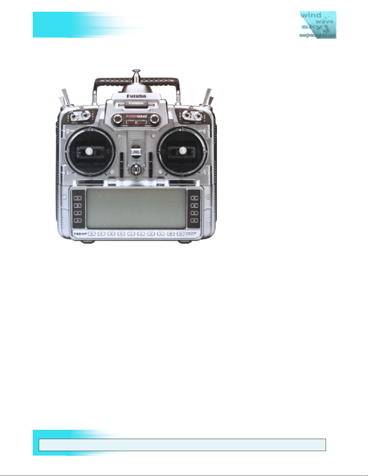
Figure 2 The First Version of the Futaba 9Z
The original 9Z is shown in Figure 2 above. Notice the differences when compared to
other 9Z models: The unique PCM1024Z logo between the two dials on the front face
and the unique button text and colouring around the LCD.
WARNING: THE INFORM ATION IN THIS MANUAL IS FOR INFORMATION PURPOSES ONLY AND MAY BE INCORRECT, CAUSE DAMAGE
TO YOUR RADIO OR INJURY TO YOURSELF AND OTHERS. IF YOU USE THIS MANUAL YOU DO SO SOLEY AT YOUR OWN RISK.
www.jamesandtracy.co.uk
Page 11 of 84
Copyright 2012 jamesandtracy.co.uk
Page 12
V
THE UNOFFICIAL WORKSHOP MANUAL
FUTABA 9Z
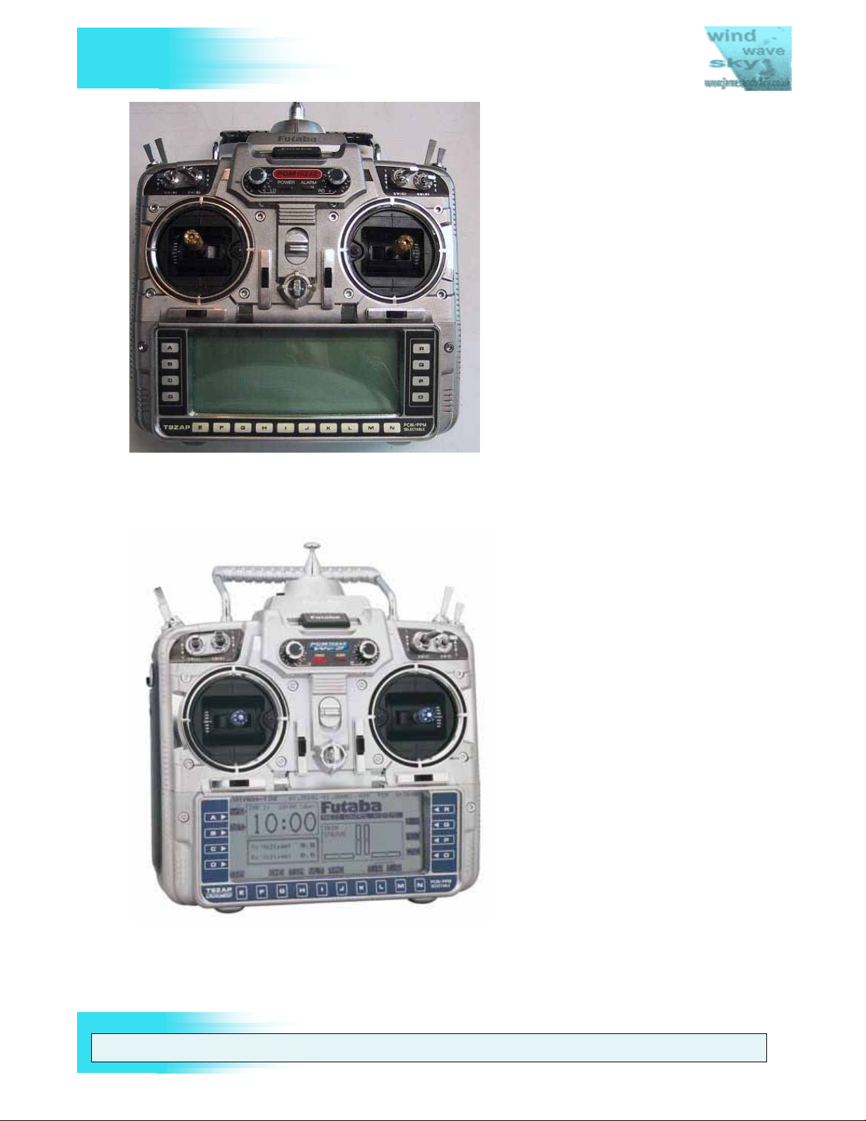
Figure 3 The Futaba 9ZAW, the second version of the 9Z (aka the 9Z WC1)
The 9Z WC1 is shown in Figure 3 above. Notice that the differences are in the same
areas as before: the PCM1024Z logo and the buttons around the LCD.
Figure 4 The FUTABA 9ZAW II, the final and most desirable version (aka the 9Z WC2)
The 9Z WC2 is shown in Figure 4 above. Notice the same differences in the same areas
as before. Now it comes with a funky blue colouring (which can appear quite grey except
in bright light). Undoubtedly the coolest of the 9Z’s, but is that worth the extra money?
WARNING: THE INFORM ATION IN THIS MANUAL IS FOR INFORMATION PURPOSES ONLY AND MAY BE INCORRECT, CAUSE DAMAGE
TO YOUR RADIO OR INJURY TO YOURSELF AND OTHERS. IF YOU USE THIS MANUAL YOU DO SO SOLEY AT YOUR OWN RISK.
www.jamesandtracy.co.uk
Page 12 of 84
Copyright 2012 jamesandtracy.co.uk
Page 13
V
FUTABA 9Z
2. HOW TO USE THIS MANUAL
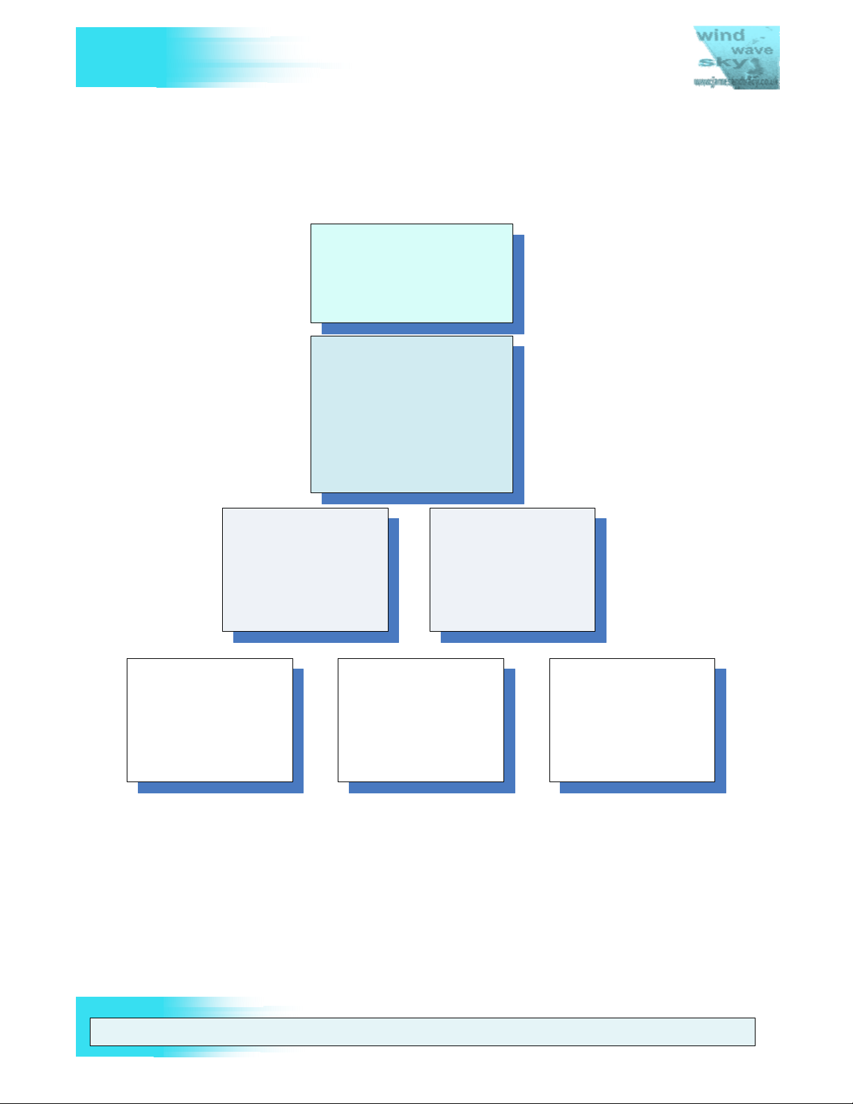
2.1. Document Structure
This workshop manual is split into sections and annexes to help you find the information
you need. The structure of the document is provided below in Figure 5.
1. Introduction
Im portant gene ral i nformation
you need to read .
2. How to Use This Manual
The master index for this
manual , so start here !
The m ast er Serv ic e , Repair
and Upg rade M at ri x ;
General preparation , tools
and techni ques .
THE UNOFFICIAL WORKSHOP MANUAL
3. Ser v i cing t h e 9Z
Specific det ailed
procedures f or serv i cing
and repair .
5. Di sa ssembli ng an d
Reas sembli n g th e 9Z ’s
Case
How to get the case apart
to serv i ce, upgrade or
repair t he item of i nteres t .
6. 9Z’s Service and Test
Menu
How to us e t h e hi dden
soft ware m enu for
cal i brat i on , t est i ng and
upgrade .
4. Upgrading and
Tailoring the 9Z
Specific det ai l ed
procedures for upgrading
and tai l ori ng y our 9Z to
your own requi rem ents .
ANNEXES
Support i ng tec hni cal
inf orm at i on and tool s for
servicing your 9Z.
Figure 5 This Workshop's Manual Structure
You can locate the service procedure you need using the Servicing and Upgrade matrix
in this document section. For example, having found the procedure you need in this
section, you’d then read the detailed process for it in Section 3 (Servicing the 9Z). This
procedure would refer you out to other areas of the document when required; e.g.
“Disassemble to Stage 3 as described in Section 5 (Disassembling and Reassembling
the 9Z’s Case) and now calibrate the Joysticks as described in Section 6 (The Futaba
Service and Test Menu)”.
WARNING: THE INFORM ATION IN THIS MANUAL IS FOR INFORMATION PURPOSES ONLY AND MAY BE INCORRECT, CAUSE DAMAGE
TO YOUR RADIO OR INJURY TO YOURSELF AND OTHERS. IF YOU USE THIS MANUAL YOU DO SO SOLEY AT YOUR OWN RISK.
www.jamesandtracy.co.uk
Page 13 of 84
Copyright 2012 jamesandtracy.co.uk
Page 14
V
FUTABA 9Z
2.2. Servicing and Upgrade Matrix
You can use the following tables to navigate this manual, solve specific issues or fix
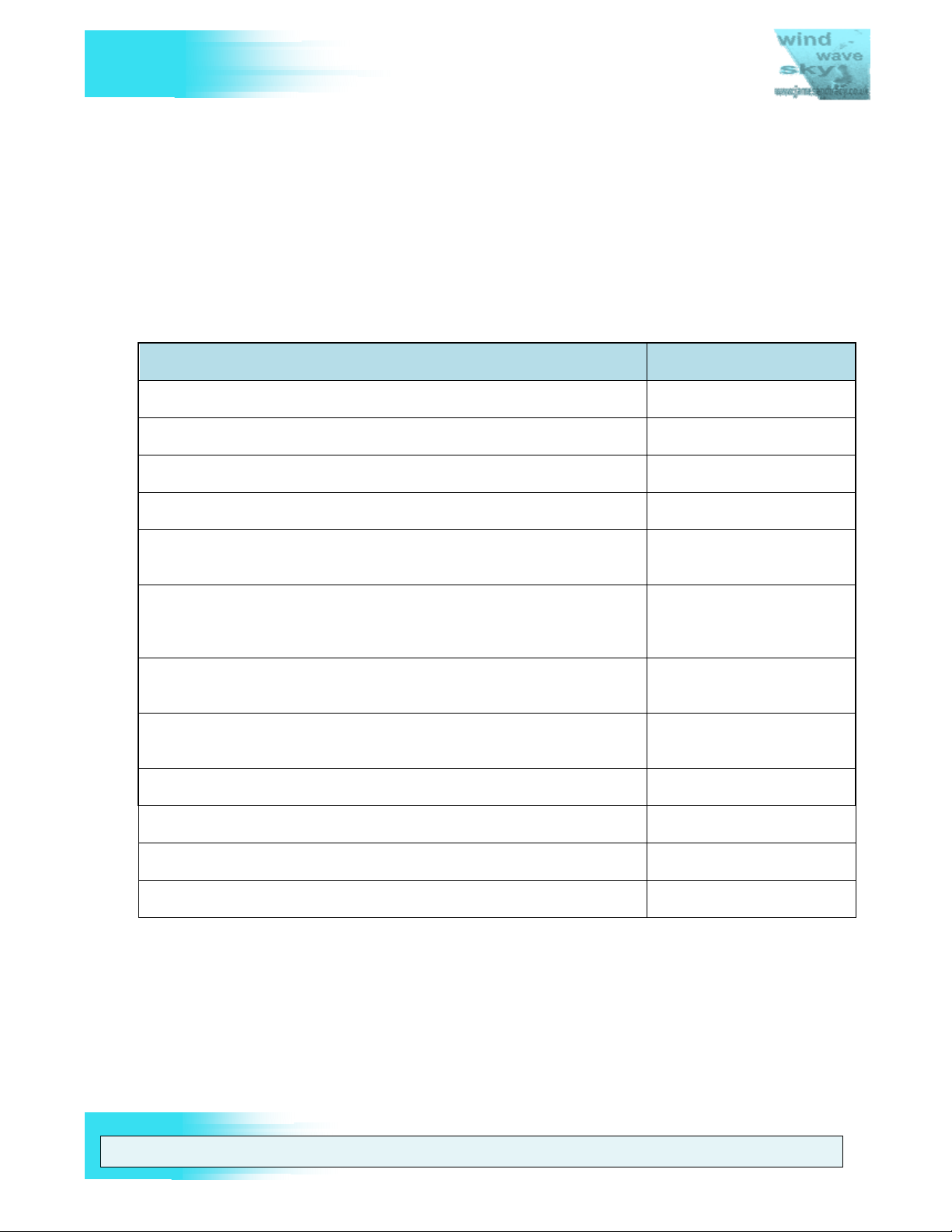
faults with your 9Z. Table 1 shows some common faults and issues and the possible ID
of the solution in Table 2. Table 2 below provides a matrix of the service and upgrade
procedures detailed in this manual, the tools required to perform them and the level of
difficulty (refer to the key below the table for an explanation of the symbols). I’ve rated
the level of difficulty based purely on what level of skill I think is needed if the correct
“recommended” tools for the job are used. You can get by without the correct tools for
many of these procedures, but the level of skill required will be significantly increased.
FAULT FINDING POSSIBLE SOLUTION
An alarm is sounding and "Back Up" is flashing on the LCD See ID 9 in Table 2
I cannot change my user name or have forgotten my password See ID 1 in Table 2
I cannot charge my battery through the charge port See ID 12 in Table 2
I cannot cycle my battery pack or use my aftermarket digital charger See ID 21 in Table 2
THE UNOFFICIAL WORKSHOP MANUAL
Poor control around stick centres. Especially a double centre to
controls when moved by small amounts. See ID’s 6 & 17 in Table 2
Poor control around stick centres. Erratic servo movement. Servos do
not centre after control movements, especially when combined with a
‘grinding’ feel to joystick controls. See ID 6 in Table 2
Erratic servo movement to joystick control or servos do not centre after
control movements, especially ‘jumping’ when switching between rates. See ID 2 in Table 2
Soft button panels do not work, require a very ‘positive’ push or work
erratically. See ID 7 in Table 2
Switch A behaves erratically or does not work See ID’s 2 & 14 in Table 2
The "On Air" and Alarm Light does not function See ID’s 13 & 20 in Table 2
Poor signal range (original 35 MHz setup) See ID 8 in Table 2
Poor signal range (following 2.4GHz conversion) See ID 20 in Table 2
Table 1 Possible solutions to common faults and issues
WARNING: THE INFORM ATION IN THIS MANUAL IS FOR INFORMATION PURPOSES ONLY AND MAY BE INCORRECT, CAUSE DAMAGE
TO YOUR RADIO OR INJURY TO YOURSELF AND OTHERS. IF YOU USE THIS MANUAL YOU DO SO SOLEY AT YOUR OWN RISK.
www.jamesandtracy.co.uk
Page 14 of 84
Copyright 2012 jamesandtracy.co.uk
Page 15

V
FUTABA 9Z
ID TASK DIFFICULTY SECTION PAGE
Section 3 – SERVICING
THE UNOFFICIAL WORKSHOP MANUAL
1 User Password
2 9Z Transmitter Calibration
3 Replacing Corner Switches
4 Replacing front face controls and switches
5 Removing the throttle ratchet for helicopter flying
6 Replacing joysticks and potentiometers
7 Replacing the LCD button panel
8 Replacing the 35MHz aerial
9 Backup (Lithium) Battery
10 Cleaning the LCD Screen
11 Replacing the LCD Screen
12 Transmitter battery pack
13 RF Module
3.1 20
3.2 20
3.3 20
3.4 21
3.4.1 21
3.4.2 23
3.5 28
3.4 29
3.5 28
3.8 33
3.9 34
3.10 35
3.11 37
14 Hard Resetting the 9Z Back to Factory Settings
Section 4 – UPGRADING
15 Adding extra 3 position switches
16 Tailoring the Reference Plane of Joysticks
17 Strengthening and repairing the Joysticks
18 Backlit LCD Display
19 9Z Mode and Version Change (e.g. ZAP to ZHP)
20 Upgrading to 2.4GHz and Telemetry
21 Cycling and Fast Charging the Transmitter Battery Pack
22 Building a DSC Cable for Direct Servo Control
Building your own CAMPAC for increased model
23
memory
3.12 38
4.1 40
4.2 40
4.3 41
4.4 43
4.5 44
4.6 45
4.7 51
4.8 54
4.9 54
WARNING: THE INFORM ATION IN THIS MANUAL IS FOR INFORMATION PURPOSES ONLY AND MAY BE INCORRECT, CAUSE DAMAGE
TO YOUR RADIO OR INJURY TO YOURSELF AND OTHERS. IF YOU USE THIS MANUAL YOU DO SO SOLEY AT YOUR OWN RISK.
www.jamesandtracy.co.uk
Page 15 of 84
Copyright 2012 jamesandtracy.co.uk
Page 16
V
FUTABA 9Z
THE UNOFFICIAL WORKSHOP MANUAL
24 Building your own PC interface for backing up the 9Z
25 Building a Training Cable for Buddy Boxing
26 Adding a 10th Channel to the 9Z
27 Building your own Futaba Service Menu Enabler
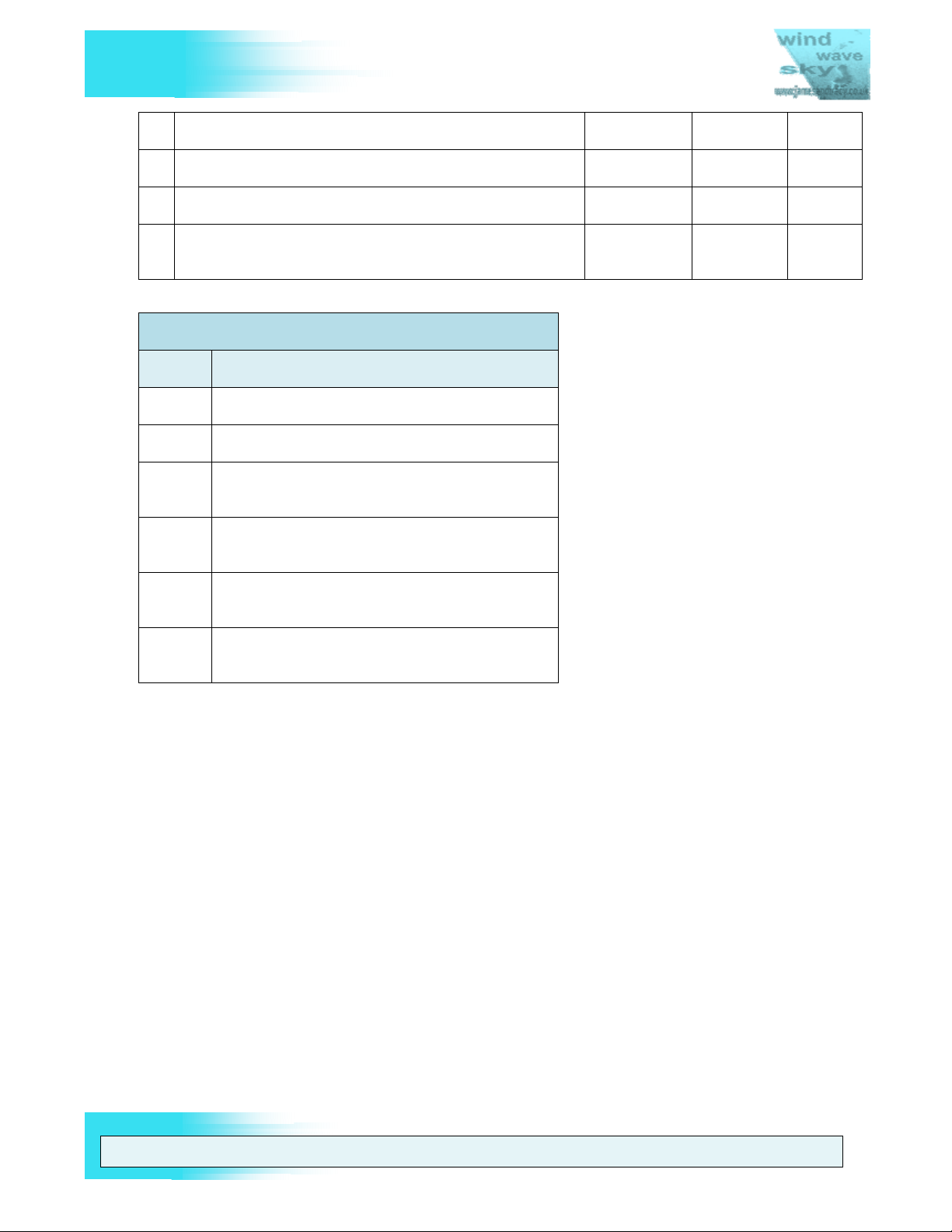
*Key for “Difficulty” Symbols in Above Table:
Symbol Explanation
No experience necessary
You can follow instructions
As above, plus you are comfortable with
household DIY
As all the above, plus you have soldering
experience
4.9 54
4.10 55
4.11 56
APPENDIX
A 77
Specific tools required or recommended
Table 2 Service and Upgrade Matrix
(Section 2.3.2)
Service and Test Menu Enabler required
(Section 6.2)
2.3. Preparation and Tools
This is an important section please read it thoroughly. If you do not have the right tools,
general techniques and mindset for the job, you will at best find it hard and at worst you
could damage your transmitter.
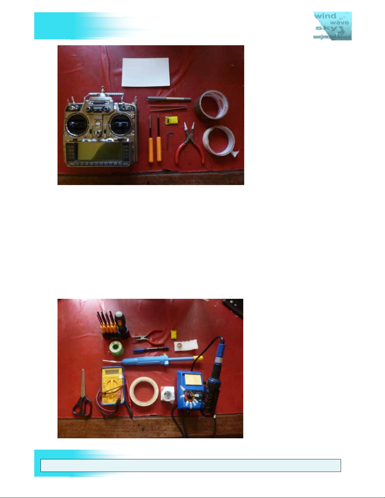
2.3.1. General Tools
The general tools you will require are shown below in Figure 6. The yellow object is the
Universal Service Menu enabler described in APPENDIX A. The tape is to protect your
pliers and screwdrivers. The white card is to stick screws through when you remove
them, and the pen is to label them so you know where they came from. I’d also suggest
you keep a camera handy to take photos for reference when you reassemble the case.
WARNING: THE INFORM ATION IN THIS MANUAL IS FOR INFORMATION PURPOSES ONLY AND MAY BE INCORRECT, CAUSE DAMAGE
TO YOUR RADIO OR INJURY TO YOURSELF AND OTHERS. IF YOU USE THIS MANUAL YOU DO SO SOLEY AT YOUR OWN RISK.
www.jamesandtracy.co.uk
Page 16 of 84
Copyright 2012 jamesandtracy.co.uk
Page 17
V
FUTABA 9Z
Figure 6 General Tools Required
THE UNOFFICIAL WORKSHOP MANUAL
2.3.2. Specific Tools
I would really suggest you invest in a solder pump (blue syringe in Figure 7) and a
variable temperature soldering iron (Blue soldering iron with dial in Figure 7) for any
work involving Printed Circuit Boards. They are both very cheap items and you’ll use
them again and again. Although you can get by without a variable temperature iron, you
must have an iron with a needle/small tip that is suitable for the delicate work of
desoldering and resoldering components. You will not be able to get by without a solder
pump or at the very least some desoldering braid - yes you might get the components off
the board, but you will probably damage them if you’re not using a pump. As a pump
costs something like £2 ($3) you’d be a fool to attempt work without one. You will also
probably need a digital multimeter (yellow meter in Figure 7), get one they’re also cheap.
Figure 7 Specific Tools - The full toolset required
WARNING: THE INFORM ATION IN THIS MANUAL IS FOR INFORMATION PURPOSES ONLY AND MAY BE INCORRECT, CAUSE DAMAGE
TO YOUR RADIO OR INJURY TO YOURSELF AND OTHERS. IF YOU USE THIS MANUAL YOU DO SO SOLEY AT YOUR OWN RISK.
www.jamesandtracy.co.uk
Page 17 of 84
Copyright 2012 jamesandtracy.co.uk
Page 18
V
FUTABA 9Z
If you intend to build your own CAMPAC for the 9Z and have a general interest in
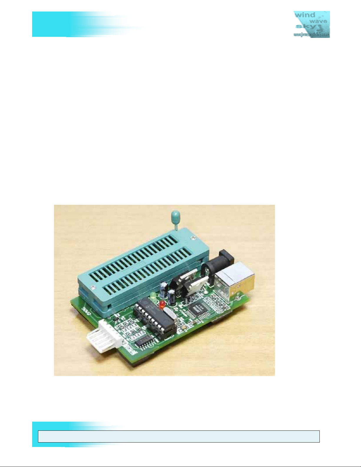
building other electronic RC gadgets then you’ll need a PIC programmer (see Figure 8).
This is a piece of kit that can upload code that you’ve either written yourself or have
downloaded from the internet to a PIC MicroChip. There are loads of different models
out there on the market and some of the Chinese copies are very cheap ($12). Do some
research before you buy, and buy only if you have a wider interest in this equipment.
That said, once you have one there are loads of excellent pre-written circuits and codes
for our hobby, so you don’t need to know about electronics to start making your own
custom kit. Using the programmer is very simple, you just hook it up to the PC and
microchip and then ‘burn’ the code onto the chip as you would a CD or DVD. Key things
to look out for in PIC programmers are:
1. That the PIC Programmer supports the chips you will be using.
2. Has a good source of software updates to remain usable with newer microchips.
3. Has USB connectivity
4. Has ICP (in-circuit programming) capability
5. Has a ZIF (Zero Insertion Force) connection for hooking up to chips
6. External power supply possible (USB power can brown out on some chips)
THE UNOFFICIAL WORKSHOP MANUAL
Figure 8 USB ICP PIC programmer with ZIF 'hook up' for the chip in green/blue.
2.3.3. Working with Printed Circuit Boards (PCBs)
Components on printed circuit boards can be damaged by static electricity. I personally
have never blown up a chip this way, but it pays to be careful. Make sure you’re wearing
WARNING: THE INFORM ATION IN THIS MANUAL IS FOR INFORMATION PURPOSES ONLY AND MAY BE INCORRECT, CAUSE DAMAGE
TO YOUR RADIO OR INJURY TO YOURSELF AND OTHERS. IF YOU USE THIS MANUAL YOU DO SO SOLEY AT YOUR OWN RISK.
www.jamesandtracy.co.uk
Page 18 of 84
Copyright 2012 jamesandtracy.co.uk
Page 19

V
FUTABA 9Z
cotton, if possible do not work in a carpeted area, pick up PCBs on the edges, earth
yourself by touching a metal bathroom tap before starting work and frequently earth
yourself on the metal sub-case of the 9Z before touching a PCB. If you’re really worried
you can buy a dedicated earth strap for your wrist very cheaply that you connect to the
9Z sub-case and it will provide a permanent earth, but I don’t have (or use) one and so
far everything has been fine.
2.3.4. Soldering
THE UNOFFICIAL WORKSHOP MANUAL
When you are soldering and desoldering components be as quick as you can as high
temperatures can damage some of them. This is why a variable temperature soldering
iron is such a good idea – you set it at a higher temperature for desoldering and it will
melt the solder before heat can be dispersed to the component. You can also use
crocodile clips as heat sinks to prevent temperature dispersing to delicate components.
There are lots of tutorials on the web about soldering and it’s very simple!
2.3.5. Working with Ribbon Cables
They’re everywhere in the 9Z. You need to be careful how you handle them and that you
don’t trap or damage them. You also need to recognise that you may need to replace
them in some instances just because they’re old (although this has never happened to
me). Do not twist them or force them, ease them back in and out. Do not remove them
with unprotected pliers. They’re likely to be as good as new inside the case, but with age
they become inflexible, and with too much pulling in and out the connectors become
detached from the ribbon. So if you can help it do not remove them unless necessary
and in the worst case, replacements can be sourced from Futaba or DigiKey/Farnell/RS
Components.
2.3.6. Attitude
Attitude….. as in yours! You need to work as if you're disarming and rearming a bomb.
That means slow thoughtful progress. If at any stage you think, "damn, doing that could
blow this thing up, but let's take a gamble" walk away and grab a cuppa! If you find
yourself about to force some bits together, walk away and grab a cuppa! If your kids
come home, walk away and grab a cuppa....well you get my drift! This is your prized
radio you're working on - take your time and keep it calm. Nothing, I repeat nothing in the
9Z, requires you to 'force it', everything clicks easily into place. There are far too many
posts on internet forums saying things like “Grab it here and pull up really hard” or “Give
it a smack here”. If you really feel the need to do this kind of thing for pleasure, invest in
a classic car or try ‘experimenting’ in your sex life, do not do it to your radio!!!
WARNING: THE INFORM ATION IN THIS MANUAL IS FOR INFORMATION PURPOSES ONLY AND MAY BE INCORRECT, CAUSE DAMAGE
TO YOUR RADIO OR INJURY TO YOURSELF AND OTHERS. IF YOU USE THIS MANUAL YOU DO SO SOLEY AT YOUR OWN RISK.
www.jamesandtracy.co.uk
Page 19 of 84
Copyright 2012 jamesandtracy.co.uk
Page 20

V
FUTABA 9Z
THE UNOFFICIAL WORKSHOP MANUAL
3. SERVICING THE 9Z
3.1. User Password
If you have forgotten the user password for your 9Z you can use the Service and Test
Menu to display the password, instead of having to reset it through a hard reset of the
transmitter. You will need a Service and Test Menu enabler to access the information
(see Section 6.2 and APPENDIX A)
The user password can be found on the “System Overview” screen of the Futaba Test
and Service Menus. This is fully described in the diagram in Section 6.3.
3.2. 9Z Transmitter Calibration
It is a good idea to recalibrate your transmitter after a few years of use as the hardware
settings drift. Typical symptoms include servo neutral positions ‘jumping’ at low rates and
sometimes even switches failing to work in one position.
You can test if your transmitter needs recalibration of its joysticks in the following way:
1. Start by selecting a blank (freshly reset) airplane program.
2. Go to the ATV menu
3. Hold both sticks fully up and fully right while switching between AIL, ELE, THR and
RUD. If the pointer below the graph moves even a little while you are switching
channels you radio needs calibration.
4. Repeat step 3 but now holding both sticks fully down and fully left.
5. Finally, repeat step 3 with both sticks cantered (including throttle axis).
To recalibrate your transmitter you’ll need to access the Futaba Service and Test Menu.
This is described in Section 6 (The Futaba Service and Test Menu) and you should refer
to the listed Joystick and Switch recalibration menus for the recalibration procedure.
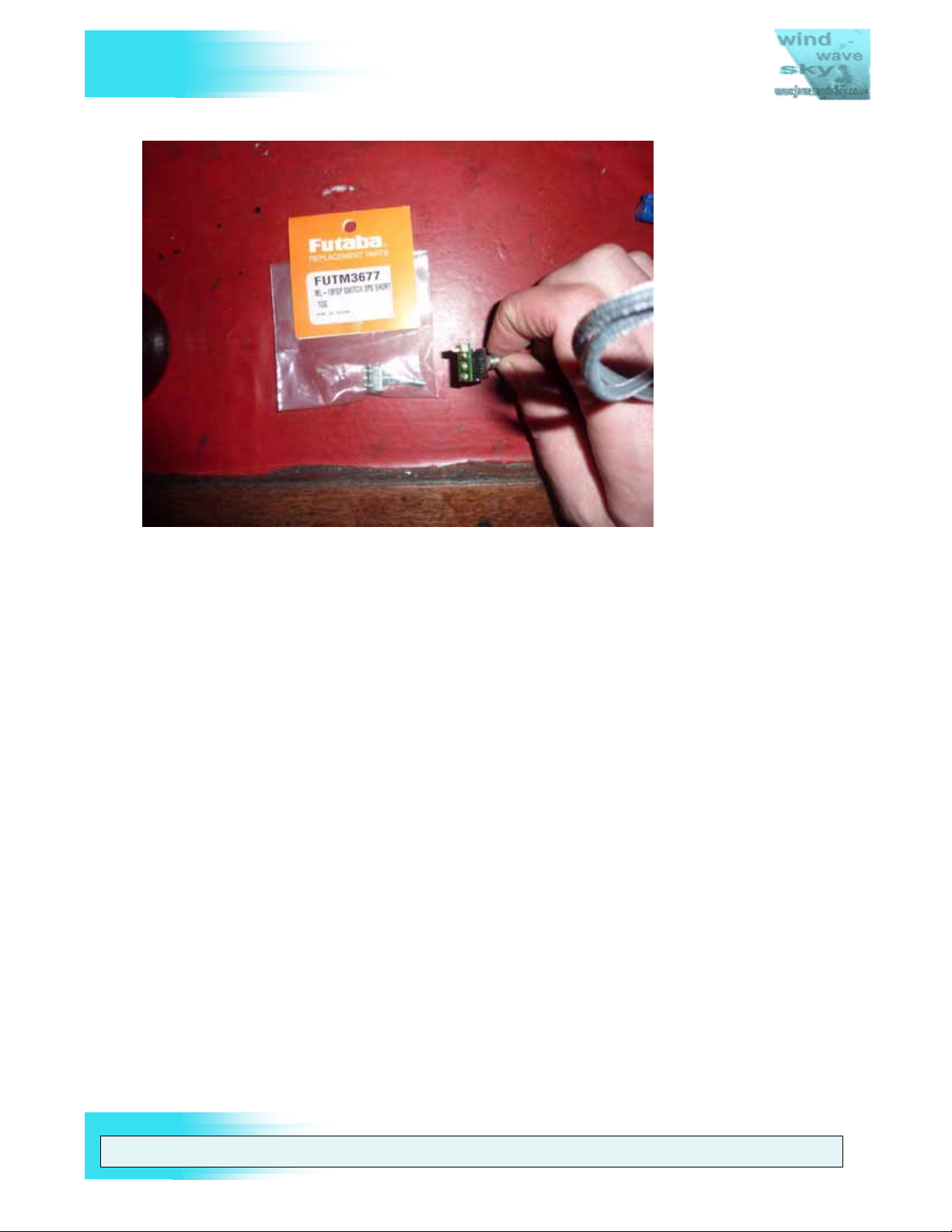
3.3. Replacing Corner Switches
This procedure relates to a like for like replacement of the Corner Switches. If you wish
to modify a switch (e.g. replace a 2 position switch with a 3 position) you should refer to
Section 4.1 (Adding extra 3 position switches).
1. Disassemble the 9Z’s case to Stage 3 as described in Section 5 (Disassembling and
Reassembling the 9Z’s Case).
2. Disconnect the ribbon cables from the corner switches.
3. Remove the switch from the corner panel by unscrewing the retaining plate
4. Desolder the switch from its mini-PCB
5. Replace with a 9Z switch and solder it to the mini-PCB
Note: The 9Z switches do not have an offset connector pattern like those of the 8U
series, the 8U series switches will fit but they require some gentle bending of the
connectors see Figure 9.
6. Reassemble is a reversal of disassembly
WARNING: THE INFORM ATION IN THIS MANUAL IS FOR INFORMATION PURPOSES ONLY AND MAY BE INCORRECT, CAUSE DAMAGE
TO YOUR RADIO OR INJURY TO YOURSELF AND OTHERS. IF YOU USE THIS MANUAL YOU DO SO SOLEY AT YOUR OWN RISK.
www.jamesandtracy.co.uk
Page 20 of 84
Copyright 2012 jamesandtracy.co.uk
Page 21
V
FUTABA 9Z
THE UNOFFICIAL WORKSHOP MANUAL
Figure 9 Corner Switch Replacement - NOTE: 8U SWITCH PART NO. IS SHOWN!
3.4. Front face controls, gimbals, and POTs
Note: I have not replaced the Front Face Controls so this procedure may be incomplete.
1. Disassemble the 9Z’s case to Stage 2 as described in Section 5 (Disassembling and
Reassembling the 9Z’s Case).
2. Access for general servicing (e.g. greasing bearings and checking POTs) and for
replacement of the front face controls and aerial requires the partial removal of the
main PCB. Make sure you are earthed and protect your tools so you don’t damage
ribbon cables etc., see Section 2.3.
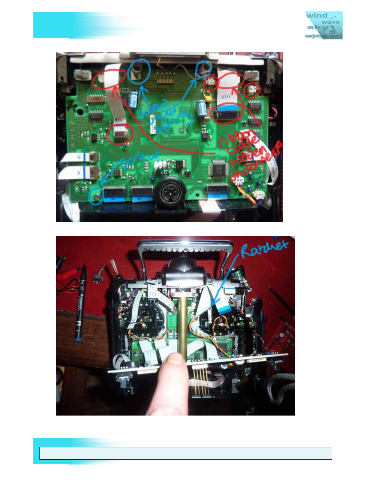
3. Remove the 4 ribbon cables, 2 connectors and 3 screws shown in Figure 10 from
the main PCB.
4. You will now be able to lever up the main PCB as shown in see Figure 11 to gain
access to the front face controls etc.
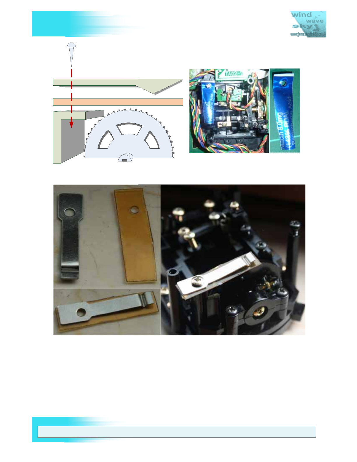
3.4.1. Removing the Throttle Ratchet for Flying Helicopters
To remove the ratchet action on the Throttle for Helicopter flying, the technique I use is
to make a ‘ratchet smoother’ from a strip of beer can (see Figure 12) or scrap plastic.
This strip is cut to fit under the existing ratchet (see Figure 11) and has a hole in one end
so it can be held in place by the existing ratchet’s screw. This whole assembly of ratchet
and ‘ratchet smoother’ is then screwed back into place (see Figure 13). I find this works
much better than flipping the metal ratchet lever upside down which still results in some
unwanted ‘ratchet’ feel. In all cases I’d advise against sanding down the plastic gear to
remove the ratchet effect as this would likely result in a non-uniform control feel unless
done very, very carefully.
WARNING: THE INFORM ATION IN THIS MANUAL IS FOR INFORMATION PURPOSES ONLY AND MAY BE INCORRECT, CAUSE DAMAGE
TO YOUR RADIO OR INJURY TO YOURSELF AND OTHERS. IF YOU USE THIS MANUAL YOU DO SO SOLEY AT YOUR OWN RISK.
www.jamesandtracy.co.uk
Page 21 of 84
Copyright 2012 jamesandtracy.co.uk
Page 22
V
FUTABA 9Z
THE UNOFFICIAL WORKSHOP MANUAL
Figure 10 Removing the main PCB
Figure 11 Lever up the PCB - Note: Metal Ratchet on Throttle at Right
WARNING: THE INFORM ATION IN THIS MANUAL IS FOR INFORMATION PURPOSES ONLY AND MAY BE INCORRECT, CAUSE DAMAGE
TO YOUR RADIO OR INJURY TO YOURSELF AND OTHERS. IF YOU USE THIS MANUAL YOU DO SO SOLEY AT YOUR OWN RISK.
www.jamesandtracy.co.uk
Page 22 of 84
Copyright 2012 jamesandtracy.co.uk
Page 23
V
THE UNOFFICIAL WORKSHOP MANUAL
FUTABA 9Z
RATCHET
RA TCHE T S M OOTH E R
GIMBAL GEAR
Figure 12 Making and installing a "Ratchet Smoother”.
RATCHET SMOOTHER MADE FROM DR INKS C A N
Figure 13 Another example of a ratchet smoother
3.4.2. Replacing the Joysticks and Potentiometers (POTS)
The joysticks on the 9Z weaken over time and can crack, whilst you can repair them
using the procedure in Section 3.4, they are easy to replace at the same time as you
service the complete 9Z gimbal assembly (inc. Potentiometer replacement). If you are
replacing the joysticks then you should also replace the POTS at the same time.
Potentiometers or POTS are used in a transmitter to sense how far the user has moved
the joystick. After some years the POTS inner surfaces wear and control becomes
erratic or inaccurate. When this occurs they need to be replaced. This procedure may
WARNING: THE INFORM ATION IN THIS MANUAL IS FOR INFORMATION PURPOSES ONLY AND MAY BE INCORRECT, CAUSE DAMAGE
TO YOUR RADIO OR INJURY TO YOURSELF AND OTHERS. IF YOU USE THIS MANUAL YOU DO SO SOLEY AT YOUR OWN RISK.
www.jamesandtracy.co.uk
Page 23 of 84
Copyright 2012 jamesandtracy.co.uk
Page 24

V
FUTABA 9Z
look difficult, but it really isn’t as long as you remember to keep all those little springs
and screws safe once you’ve removed them. POTS are fairly standard items in the
electronic industry, but their calibration value is critical so make sure you get the right
ones. There are two sorts used on the 9Z series of transmitters – one is blue and one is
silver. Futaba can provide exact replacements or you can find the little numbers written
on the POTS and plug this into Google to find an aftermarket replacement. The required
part numbers can be found in APPENDIX C.
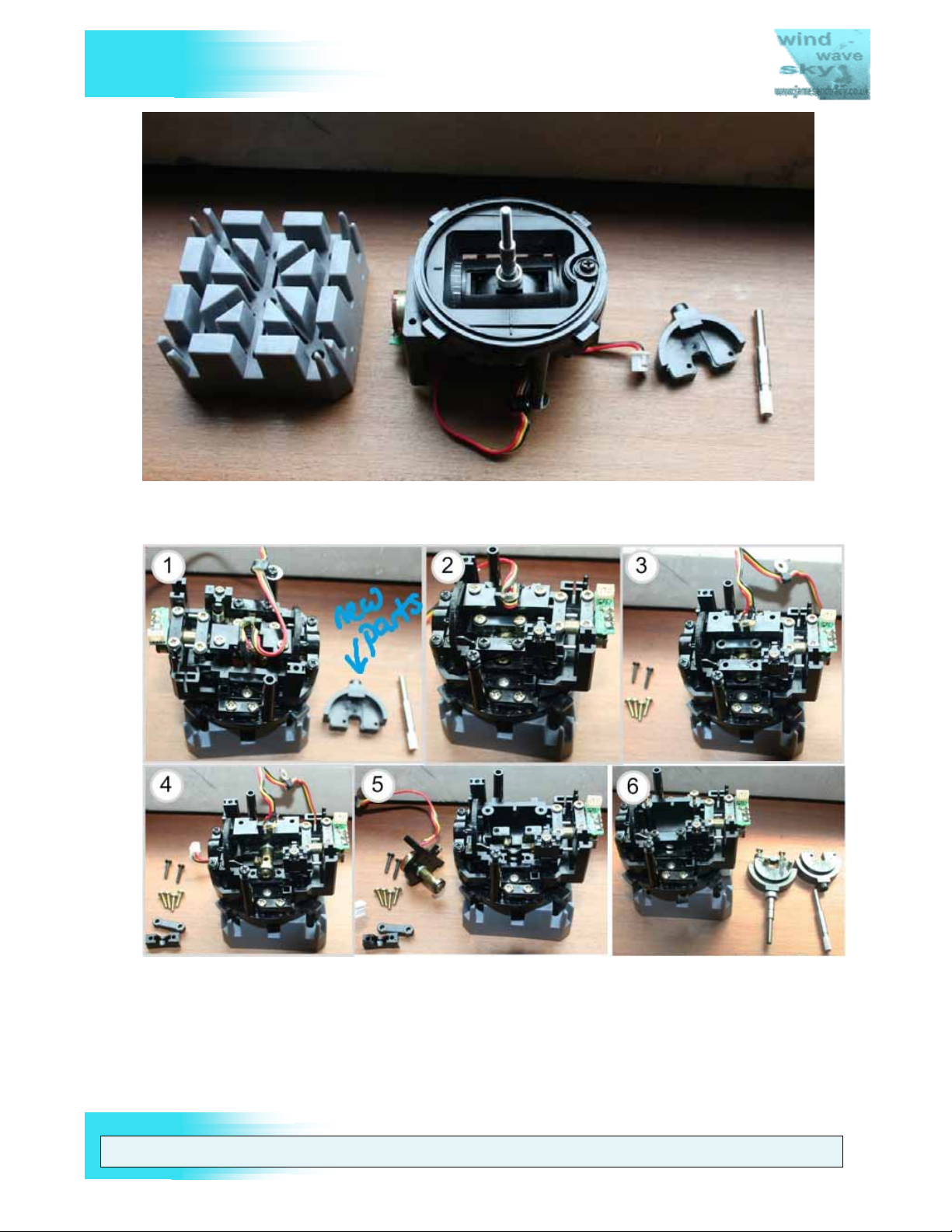
To remove and replace the POTS and joysticks in your 9Z simply follow the procedure
below:
1. Remove the 4 Allen key screws around the joystick/gimbals (see Figure 34 on Page
40).
2. Twist out the joystick gimbal and disconnect the associated cable (see Figure 14).
3. Remove the retainers for horizontal axis and remove both the pot and the joystick
(see Figure 15).
4. If you are replacing the joysticks assemble the parts as shown in Figure 18. It may
well be a good idea to add a strengthening collet (see Section 4.3) to the assembly
to prevent future joystick failure as this is a fairly common issue.
THE UNOFFICIAL WORKSHOP MANUAL
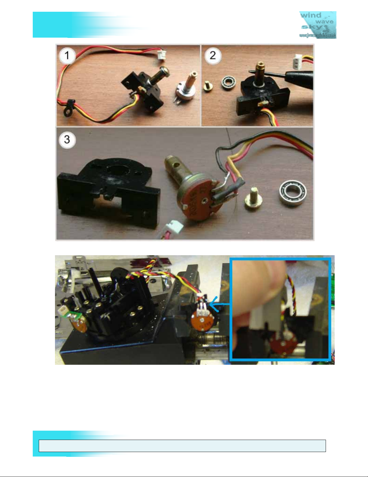
5. Unscrew the ball bearing at the end of the pot and remove the horizontal POT from
the assembly (see Figure 16).
6. Slice the heat shrink tubing on the horizontal POTS connectors and desolder the
wires.
7. Solder a new POT onto the wires. It is very important to add new heat shrink tubing
to protect the contacts or you risk a short circuit when in use.
8. Reassemble the POT in the horizontal axis gimbal using red Locktite or similar as
before and re-fit the joystick.
9. Unscrew the vertical axis POT retainers and pop out the POT (see Figure 19).
10. Desolder the connector PCB, solder it onto a new POT (see Figure 20).
11. Finally, reassemble the vertical axis gimbal. Again, make sure you use red Locktite
or similar when installing the new assembly back into the gimbal.
12. Reassemble the rest of the gimbal unit and replace the whole fully serviced unit
back in your 9Z. Reassembly is a reversal of disassembly.
WARNING: THE INFORM ATION IN THIS MANUAL IS FOR INFORMATION PURPOSES ONLY AND MAY BE INCORRECT, CAUSE DAMAGE
TO YOUR RADIO OR INJURY TO YOURSELF AND OTHERS. IF YOU USE THIS MANUAL YOU DO SO SOLEY AT YOUR OWN RISK.
www.jamesandtracy.co.uk
Page 24 of 84
Copyright 2012 jamesandtracy.co.uk
Page 25
V
THE UNOFFICIAL WORKSHOP MANUAL
FUTABA 9Z
Figure 14 Joystick gimbal removed (Note: new joystick parts for replacement on the right)
Figure 15 Disassemble the horizontal axis POT and joystick (new joystick parts in 1 & 6)
WARNING: THE INFORM ATION IN THIS MANUAL IS FOR INFORMATION PURPOSES ONLY AND MAY BE INCORRECT, CAUSE DAMAGE
TO YOUR RADIO OR INJURY TO YOURSELF AND OTHERS. IF YOU USE THIS MANUAL YOU DO SO SOLEY AT YOUR OWN RISK.
www.jamesandtracy.co.uk
Page 25 of 84
Copyright 2012 jamesandtracy.co.uk
Page 26
V
FUTABA 9Z
THE UNOFFICIAL WORKSHOP MANUAL
Figure 16 Unscrew the ball bearing from the horizontal axis POT
Figure 17 Slice the heat-shrink tubing and desolder the POT
WARNING: THE INFORM ATION IN THIS MANUAL IS FOR INFORMATION PURPOSES ONLY AND MAY BE INCORRECT, CAUSE DAMAGE
TO YOUR RADIO OR INJURY TO YOURSELF AND OTHERS. IF YOU USE THIS MANUAL YOU DO SO SOLEY AT YOUR OWN RISK.
www.jamesandtracy.co.uk
Page 26 of 84
Copyright 2012 jamesandtracy.co.uk
Page 27

V
THE UNOFFICIAL WORKSHOP MANUAL
FUTABA 9Z
Figure 18 Assembling a new joystick (note: DIY strengthening collet modification)
1 2
3 4
Figure 19 Remove the vertical axis POT retaining plates and withdraw the POT
WARNING: THE INFORM ATION IN THIS MANUAL IS FOR INFORMATION PURPOSES ONLY AND MAY BE INCORRECT, CAUSE DAMAGE
TO YOUR RADIO OR INJURY TO YOURSELF AND OTHERS. IF YOU USE THIS MANUAL YOU DO SO SOLEY AT YOUR OWN RISK.
www.jamesandtracy.co.uk
Page 27 of 84
Copyright 2012 jamesandtracy.co.uk
Page 28

V
FUTABA 9Z
Figure 20 Desolder the connector PCB (green) from the POT
3.5. Replacement of LCD button panels
THE UNOFFICIAL WORKSHOP MANUAL
The 9Z transmitter, like its predecessor the 9V, uses software buttons that are activated
by clicking the corresponding button on the LCD button panel. However, unlike the 9V,
these button panels are manufactured as self adhesive units (see Figure 21) and it is
common for these panels to become worn and fail over the life of the transmitter.
Figure 21 The three LCD Button Panels shown on a 9ZHP WC2
The primary issue with replacing these panels is finding a supplier that still has stock of
the required spare parts. At present it appears that stock of the original 9ZAP/ZHP and
WARNING: THE INFORM ATION IN THIS MANUAL IS FOR INFORMATION PURPOSES ONLY AND MAY BE INCORRECT, CAUSE DAMAGE
TO YOUR RADIO OR INJURY TO YOURSELF AND OTHERS. IF YOU USE THIS MANUAL YOU DO SO SOLEY AT YOUR OWN RISK.
www.jamesandtracy.co.uk
Page 28 of 84
Copyright 2012 jamesandtracy.co.uk
Page 29

V
FUTABA 9Z
WC1 panels has been completely exhausted. Partial stock of the WC2 panels is still
available, but difficult to locate. It should be noted that each model has superficially
different button panels (e.g. different branding), but all panels are interchangeable
between the 9Z models. This has led to many early 9Z’s and 9ZHP’s being ‘re-branded’
by the fitting of 9ZAP WC2 panels.
If you can find stock, replacement of the panels is simple:
1. Purchase the required panels (see APPENDIX C for part numbers)
2. Lever up the old panels with an old credit card or other hard plastic card that has
been ‘sharpened’ so that it can slip under the panel and break the initial seal. You
can use a knife to start things off, but be very careful as you can easily scratch the
9Z case. For this reason, do not be tempted to use a screwdriver.
3. After removing the self adhesive panels glue residue will be left on the 9Z case.
Carefully remove all this residue by rubbing with your finger and then clean the area
with a damp soapy cloth. Finally, wipe over to remove any soap residue with a clean
damp cloth.
4. After everything has thoroughly dried, peel the backing from the new button panels
and apply them to the 9Z case.
THE UNOFFICIAL WORKSHOP MANUAL
3.6. 35MHz Aerial Replacement and Servicing
Note: I have not replaced the Aerial so this procedure may be incomplete.
Warning: Always do a range test after replacing or servicing the aerial. If for some
reason you lose RF range after changing the aerial, then it is likely that this spring clip
has become dislodged. If this is the case then you’ll need to remove the transmitter case
top to gain access to the clip. To do this you will need to disassemble the case to Stage
3 (see Section 5) and then completely remove the bolts shown in Figure 57 on page 61.
The 35MHz aerial that comes with the 9Z cannot be removed for servicing without some
disassembly of the transmitter. However, this disassembly is trivial in most cases and
simply requires removal of the battery pack if you are careful. It is retained in the case by
an Allen key style bolt at its base and the electrical contact for RF transmission is made
by a spring clip in the ‘ball joint’ at the top of the transmitter case (see Figure 22).
Figure 22 Allen head bolt at the bottom of the 9Z aerial (3/32" or 3mm head)
WARNING: THE INFORM ATION IN THIS MANUAL IS FOR INFORMATION PURPOSES ONLY AND MAY BE INCORRECT, CAUSE DAMAGE
TO YOUR RADIO OR INJURY TO YOURSELF AND OTHERS. IF YOU USE THIS MANUAL YOU DO SO SOLEY AT YOUR OWN RISK.
Page 29 of 84
www.jamesandtracy.co.uk
Copyright 2012 jamesandtracy.co.uk
Page 30

V
FUTABA 9Z
To remove the aerial for servicing you have two options to access and undo the Allen
key bolt that retains it at its base:
Option 1 – Full Access: Disassemble the case and remove the main PCB as described
in Section 3.4. Insert a 3/32” Allen key (although some are 3mm) to undo the bolt
through the access hole in the base of the battery compartment and undo the bolt (see
Figure 23). Maintain pressure on the bolt throughout removal and replacement so it
doesn’t fall out of its slot. The advantage of this option is that it will give you full access
to the bottom of the antenna should the worst happen and the bolt become dislodged
and falls out during servicing.
Option 2 – Restricted Access: Disassemble to Stage 1 as described in Section 5.1 (i.e.
you only need to remove the transmitter battery pack). Insert a 3/32” Allen key (although
some are 3mm) to undo the bolt through the access hole in the base of the battery
compartment and undo the bolt (see Figure 23). Maintain pressure on the bolt
throughout removal and replacement so it doesn’t fall out of its slot. Be very careful! If
the bolt drops out you will need to disassemble the transmitter to retrieve it and during
disassembly you are likely to jiggle the missing bolt deeper into your transmitter’s
internal components.
THE UNOFFICIAL WORKSHOP MANUAL
Figure 23 The access hole for the aerial retaining bolt in the battery compartment
3.7. Backup (Lithium) Battery
The main back up or memory battery should be replaced every 5 years. Failure to do so
will eventually result in the loss of all your model settings when the battery is exhausted.
When this happens a warning message (BACK UP) will be displayed on the LCD and
the 9Z will emit an alarm tone that you cannot cancel. Replacement of this battery is not
difficult, but you really will need the right tools (refer to Section 2.3).
WARNING: THE INFORM ATION IN THIS MANUAL IS FOR INFORMATION PURPOSES ONLY AND MAY BE INCORRECT, CAUSE DAMAGE
TO YOUR RADIO OR INJURY TO YOURSELF AND OTHERS. IF YOU USE THIS MANUAL YOU DO SO SOLEY AT YOUR OWN RISK.
www.jamesandtracy.co.uk
Page 30 of 84
Copyright 2012 jamesandtracy.co.uk
Page 31

V
FUTABA 9Z
Note: This procedure requires the partial removal of one of the LCD’s PCBs. Make sure
you are earthed and protect your tools so you don’t damage ribbon cables etc., again
see Section 2.3.
1. Obtain a replacement lithium battery from Digikey, Farnell or RS Components. The
replacement is a BR2032/HEN (£1.47p). Do not be tempted to use a cheaper
CR2032!
2. Label the new battery with the date of replacement and protect with tape if required
(see Figure 24)
THE UNOFFICIAL WORKSHOP MANUAL
Figure 24 Label and protect the new battery
3. Make sure you have the tools to access the Service and Test Menu ready (see
Section 6.2)
4. Backup your settings for your 9Z onto a CAMPAC 64 or Ultrapac 64 as they will be
wiped by the battery replacement process.
5. Disassemble the 9Z’s case to Stage 4 as described in Section 5 (Disassembling and
Reassembling the 9Z’s Case).
6. Remove the 4 screws retaining the top PCB of the LCD assembly (see Figure 25).
7. Flip the top PCB onto its back (see Figure 26).
WARNING: THE INFORM ATION IN THIS MANUAL IS FOR INFORMATION PURPOSES ONLY AND MAY BE INCORRECT, CAUSE DAMAGE
TO YOUR RADIO OR INJURY TO YOURSELF AND OTHERS. IF YOU USE THIS MANUAL YOU DO SO SOLEY AT YOUR OWN RISK.
www.jamesandtracy.co.uk
Page 31 of 84
Copyright 2012 jamesandtracy.co.uk
Page 32

V
FUTABA 9Z
THE UNOFFICIAL WORKSHOP MANUAL
Figure 25 Removing the top PCB of the LCD Assembly
Figure 26 Top PCB 'Flipped' and Battery Terminals Exposed
8. Desolder and remove the old battery terminals using your iron and pump, being
careful to note which terminal is +ve and which is –ve (see Figure 26)
9. Double check you are going to place your new battery the right way round and, once
you are sure, solder it in.
WARNING: THE INFORM ATION IN THIS MANUAL IS FOR INFORMATION PURPOSES ONLY AND MAY BE INCORRECT, CAUSE DAMAGE
TO YOUR RADIO OR INJURY TO YOURSELF AND OTHERS. IF YOU USE THIS MANUAL YOU DO SO SOLEY AT YOUR OWN RISK.
www.jamesandtracy.co.uk
Page 32 of 84
Copyright 2012 jamesandtracy.co.uk
Page 33

V
FUTABA 9Z
10. Reassemble the transmitter
11. Fit the Service Menu Enabler, turn on the transmitter and access the Service and
Test Menu (Section 6.2)
12. Recalibrate and test everything using the Service and Test Menu as described in
Section 6.
13. Turn off and remove the Service Menu Enabler, and re-load any saved settings.
14. Put a label (with the date on it) on the inside of the battery hatch to remind you when
you did the replacement.
3.8. Cleaning the LCD Screen
Note: I have not directly tested this procedure. Also note that this procedure requires the
removal of the LCD’s PCB assembly. Make sure you are earthed and protect your tools
so you don’t damage ribbon cables etc., again see Section 2.3.
1. Disassemble the 9Z’s case to Stage 4 as described in Section 5 (Disassembling and
Reassembling the 9Z’s Case).
2. Remove the 2 black screws retaining the LCD assembly (see Figure 27)
THE UNOFFICIAL WORKSHOP MANUAL
3. You should now be able to flip the whole LCD assembly out to clean it (see Figure
28 in Section 3.9). Note that ribbon cables will still be attached so be careful not to
stress them.
Figure 27 Removing the LCD Assembly
WARNING: THE INFORM ATION IN THIS MANUAL IS FOR INFORMATION PURPOSES ONLY AND MAY BE INCORRECT, CAUSE DAMAGE
TO YOUR RADIO OR INJURY TO YOURSELF AND OTHERS. IF YOU USE THIS MANUAL YOU DO SO SOLEY AT YOUR OWN RISK.
www.jamesandtracy.co.uk
Page 33 of 84
Copyright 2012 jamesandtracy.co.uk
Page 34

V
FUTABA 9Z
3.9. Replacing the LCD Screen
Note: I have not directly tested this procedure. Also note that this procedure requires the
removal of the LCD’s PCB assembly. Make sure you are earthed and protect your tools
so you don’t damage ribbon cables etc., again see Section 2.3.
Whilst it is possible to replace a cracked or damaged 9Z LCD screen, the cost is usually
prohibitive as Futaba charge $100’s for the replacement part. This usually means that it
is cheaper to buy a replacement transmitter or live with the damage. However, after
market replacements from a generic component supplier like Farnell, RS Online or
Digikey are likely to be much, much cheaper. You can either try to source a generic
replacement from these companies or purchase a second hand 9Z and swap the LCD.
Futaba supply the complete assembly so there is no need to do more than disconnect
the ribbon cables (see APPENDIX C for part numbers), although it may be possible to
purchase the individual components from them. The procedure detailed below is for
THE UNOFFICIAL WORKSHOP MANUAL
replacement of the component LCD panel alone
PCB boards). This can reduce the cost to a fraction of the Futaba “full assembly” price.
Though please be warned – replacing an LCD is probably the most difficult procedure in
this manual. However, if you want to replace your screen follow the procedure below:
1. Follow the procedure in Section 3.8 to remove the LCD Assembly
(i.e. without replacement of the original
2. Remove the corner screws of the LCD Assembly and partially disassemble it (see
Figure 28). Be careful not to damage the ribbon cables linking the assembly to the
9Z – if in doubt remove any that get in the way.
Figure 28 LCD Assembly removed and partially disassembled
WARNING: THE INFORM ATION IN THIS MANUAL IS FOR INFORMATION PURPOSES ONLY AND MAY BE INCORRECT, CAUSE DAMAGE
TO YOUR RADIO OR INJURY TO YOURSELF AND OTHERS. IF YOU USE THIS MANUAL YOU DO SO SOLEY AT YOUR OWN RISK.
www.jamesandtracy.co.uk
Page 34 of 84
Copyright 2012 jamesandtracy.co.uk
Page 35

V
FUTABA 9Z
3. Remove the PCB holding the LCD screen and metal shield
4. Remove the metal shield by carefully bending the retaining lugs (see Figure 29)
5. Very carefully flip the exposed LCD over to one side so it is off the PCB. It will still
be attached to the PCB by a short ribbon cable at one end, be extremely careful not
to damage this cable (see Figure 29).
6. Disconnect the short ribbon cable and replace the LCD.
7. Reassemble the LCD Assembly being careful to ensure a good contact between
LCD and PCB contacts (Lines will appear on your LCD if a bad contact is made)
8. Reassemble your transmitter enough to test the new LCD. Do not fully reassemble
as it is likely that you may have a bad contact in the LCD (see above).
9. If everything is working fine, clean the LCD with a soft cloth to remove finger marks
and then fully reassemble the transmitter. Reassembly is a reversal of disassembly.
THE UNOFFICIAL WORKSHOP MANUAL
Figure 29 Complete disassembly of middle PCB and LCD Panel
3.10. Transmitter battery pack
Note: The inclusion of a diode within the pack limits your safe charging rate to 300mA
without a special diode ‘jumper’ and prevents your digital charger from sensing battery
voltage or cycling the pack. It is recommended that you make a simple diode “jumper”
and upgrade your pack using the instructions in Section 4.7.
The 9Z’s transmitter battery pack is somewhat different from the usual transmitter packs
you can buy readily from the internet or your local model shop. It is a cartridge style pack
with an in-built PCB and 0.1” single row receptacle connector (PCB header style) that
connects to the transmitter. This has allowed Futaba to sell replacement packs at a
ridiculously high cost as, in bulk, the unit must cost very little to make. Despite its
WARNING: THE INFORM ATION IN THIS MANUAL IS FOR INFORMATION PURPOSES ONLY AND MAY BE INCORRECT, CAUSE DAMAGE
TO YOUR RADIO OR INJURY TO YOURSELF AND OTHERS. IF YOU USE THIS MANUAL YOU DO SO SOLEY AT YOUR OWN RISK.
www.jamesandtracy.co.uk
Page 35 of 84
Copyright 2012 jamesandtracy.co.uk
Page 36

V
FUTABA 9Z
oddities, under the skin it is almost exactly the same as any other transmitter pack. So
before spending serious cash replacing it, why not just service it?
The battery cartridge is very simple and consists of only 4 components:
1. The battery cartridge case top (Part No. 1M10E17801 “UPPER CASE NT-8A”)
2. The battery cartridge case bottom (Part No. 1M10E17901 “BOTTOM CASE NT-8A”)
3. The battery (a standard transmitter pack)
4. The mini-PCB (Part no. T56800 “PCB 9V T982 BATT ASSY”, which is very simple
and has 1 x 400mA Schottky diode, 1 x 0.1” receptacle and 1 x standard charge
socket)
There are two common things that happen with 9Z battery packs that require servicing:
1. The NiCad battery becomes exhausted and needs to be replaced.
2. Fast charging above 400mA blows the diode and the battery will not charge through
the main charge socket (there will usually be some melting of the case at its end).
Figure 30 shows a blown diode on the battery’s mini-PCB.
THE UNOFFICIAL WORKSHOP MANUAL
Figure 30 Blown Schottky Diode on Mini PCB
To replace the NiCad battery the operation is simple, although I’d recommend you
replace it with a higher capacity Nimh pack and preferably with your own DIY pack made
from Sanyo Eneloop batteries (the only currently available low self discharge batteries
that live up to their promised performance). Do not bother with Lipos, you get very little
increased performance over Eneloops and you will not be able to do a like for like
replacement. To replace the battery follow the procedure below and refer to Section 4.7
for additional recommendations:
1. Open up the battery case by unscrewing the retaining screws.
2. Either purchase a standard battery pack or make one up from Eneloops
3. Slide out the mini-PCB and old battery pack
4. Desolder the old battery pack
WARNING: THE INFORM ATION IN THIS MANUAL IS FOR INFORMATION PURPOSES ONLY AND MAY BE INCORRECT, CAUSE DAMAGE
TO YOUR RADIO OR INJURY TO YOURSELF AND OTHERS. IF YOU USE THIS MANUAL YOU DO SO SOLEY AT YOUR OWN RISK.
www.jamesandtracy.co.uk
Page 36 of 84
Copyright 2012 jamesandtracy.co.uk
Page 37

V
FUTABA 9Z
5. Solder in the new battery pack
6. Reassemble
You can test for a blown diode on the mini-PCB during the above operation just use the
diode test facility on your multimeter to make sure it passes current in only one direction.
However, as the stock diode is only 400mA and far too small for bullet proof charging
using modern equipment, it is suggested that even if the diode is functional you should
replace it by upgrading to a larger 3A version (see Section 4.7 for the procedure).
3.11. RF Module
The RF Module in the 9Zap is a TK variant, rather than the TP variant used in 8u’s and
9c’s. Although there are some posts on the internet suggesting otherwise (some even
from Futaba), to all intents and purposes these seem to be interchangeable for PPM
operation and a Futaba agent even confirms this in one positing. Certainly, I have used
both TK and TP variants in my 8u’s, 9c’s, 9VAP and 9ZAP without issues for PPM
operation. So whilst I’m not 100% certain, you can probably swap any one with any other
without issues as long as you’re using PPM. For PCM operation, you should probably
stick with the appropriate module for the transmitter.
One of the main issues with both TK and TP modules (and with aftermarket 2.4GHz
conversions), is the sudden loss of the ‘On Air’ LCD message and associated alarm
light. Futaba modules use the RF Pin-out shown in Figure 31 which is more fully
described in APPENDIX B.
THE UNOFFICIAL WORKSHOP MANUAL
1 RF PINOUT 5
Figure 31 Futaba RF Module Pin-out Numbering
Pin number 3 is the RF Output Indicator. This pulls to ground (Pin number 4) when RF is
detected. Connecting these two pins together tells the radio it is transmitting and causes
it to show the “On Air” LCD message and associated alarm light.
WARNING: THE INFORM ATION IN THIS MANUAL IS FOR INFORMATION PURPOSES ONLY AND MAY BE INCORRECT, CAUSE DAMAGE
TO YOUR RADIO OR INJURY TO YOURSELF AND OTHERS. IF YOU USE THIS MANUAL YOU DO SO SOLEY AT YOUR OWN RISK.
www.jamesandtracy.co.uk
Page 37 of 84
Copyright 2012 jamesandtracy.co.uk
Page 38

V
THE UNOFFICIAL WORKSHOP MANUAL
FUTABA 9Z
Figure 32 Weak solder joint in RF Module
There is a weakness in the TP and TK models related to their internal metal shielding.
The socket for Pin 4 (ground) is directly soldered onto this metal shielding and this
connection is structurally weak (see Figure 32). When it breaks, the “On Air” message
and alarm will fail to be displayed. The solution is simple:
1. Undo the 2 retaining screws on the module’s case
2. Slide the bottom part of the case upwards to release it from its retaining clips and
then lift it off
3. You’ll now see the metal shielding case around the PCB. Locate the RF Pin-out
socket (Top end on the back of the module).
4. Locate Pin 4 and see if it is still connected to the metal shielding. Wiggle the
shielding a little to check for a broken connection.
5. Resolder the connection if necessary
If you are using an aftermarket replacement and you want to have the “On Air” message
and alarm, you can attempt to reproduce this same behavior by directly connecting Pin 3
and Pin 4.
3.12. Hard Resetting the 9Z Back to Factory Settings
Note: I have not tested this procedure myself, but there is a lot of information on the
internet suggesting that the following will hard reset a 9Z. You will need to access the
Futaba Service Menu which requires a Service Menu Enabler (see Section 6)
Whilst removing the back-up battery in a 9Z will hard reset the transmitter, there is an
easier way to return your set to factory defaults without disassembling it. This involves
shorting two contacts beneath the battery compartment for several seconds. After any
hard reset you need to recalibrate your set. The following procedure will hard reset your
9Z:
WARNING: THE INFORM ATION IN THIS MANUAL IS FOR INFORMATION PURPOSES ONLY AND MAY BE INCORRECT, CAUSE DAMAGE
TO YOUR RADIO OR INJURY TO YOURSELF AND OTHERS. IF YOU USE THIS MANUAL YOU DO SO SOLEY AT YOUR OWN RISK.
www.jamesandtracy.co.uk
Page 38 of 84
Copyright 2012 jamesandtracy.co.uk
Page 39

V
FUTABA 9Z
1. Disassemble the 9Z’s case to Stage 1 as described in Section 5 (Disassembling and
Reassembling the 9Z’s Case).
2. Open the now empty battery compartment and locate the two access holes shown
in Figure 33.
3. Beneath these access holes are 2 solder pads that need to be shorted for several
seconds to hard reset the transmitter (e.g. connected together with a jumper through
the access holes).
4. Reassemble the transmitter and turn on to check that a hard reset has been
performed.
5. Fit the Service Menu Enabler, turn on the transmitter and access the Service and
Test Menu (Section 6.2)
6. Recalibrate and test everything using the Service and Test Menu as described in
Section 6.
7. Turn off and remove the Service Menu Enabler.
THE UNOFFICIAL WORKSHOP MANUAL
Figure 33 Access holes for hard resetting a 9Z
WARNING: THE INFORM ATION IN THIS MANUAL IS FOR INFORMATION PURPOSES ONLY AND MAY BE INCORRECT, CAUSE DAMAGE
TO YOUR RADIO OR INJURY TO YOURSELF AND OTHERS. IF YOU USE THIS MANUAL YOU DO SO SOLEY AT YOUR OWN RISK.
www.jamesandtracy.co.uk
Page 39 of 84
Copyright 2012 jamesandtracy.co.uk
Page 40

V
FUTABA 9Z
4. UPGRADING AND TAILORING THE 9Z
4.1. Adding extra 3 position switches
You can upgrade your 9ZAP WC2 into a hybrid 9ZAP/ZHP for glider or helicopter flying
by changing the existing 2 position Switch E into a 3 position switch. Equally well you
can add extra 3 position switches to a 9ZAP or 9ZAP WC1 and upgrade it to WC2
status. In fact the options are endless; with any 9ZAP you can change and arrange 3
position, 2 position or Momentary (hold for on) switches to suit your flying style. You will
however need to gain access to the Service and Test Menu so first refer to Section 6.
To upgrade or change a switch type follow the procedure below:
1. For corner switches replace as detailed in Section 3.3
2. For front face or top face switches disassemble and gain access for replacement as
detailed in Section 3.4 and then refer to Section 3.3 for the actual switch
replacement process
3. After reassembly enter the Service and Test Menu as detailed in Section 6.2
4. Go to the Switch Settings screen and make the changes to reflect your choice of
switches (see Section 6.3)
THE UNOFFICIAL WORKSHOP MANUAL
5. Test the switches using the test menu (see Section 6.4)
4.2. Tailoring the Reference Plane of Joysticks
Not only can you tailor the length and angle of the joysticks, but you can also tailor their
reference plane (see Figure 34). This can be very useful in setting up the right
ergonomics on the set as our thumb joints do not operate on an X/Y plane with 0
degrees of rotational offset when we hold transmitters. I find getting this rotational offset
right to be of most benefit when I’m flying 3D Helicopter manoeuvres; everything seems
to come together more tightly and more easily.
Figure 34 Changing the Rotational Position of Joysticks
WARNING: THE INFORM ATION IN THIS MANUAL IS FOR INFORMATION PURPOSES ONLY AND MAY BE INCORRECT, CAUSE DAMAGE
TO YOUR RADIO OR INJURY TO YOURSELF AND OTHERS. IF YOU USE THIS MANUAL YOU DO SO SOLEY AT YOUR OWN RISK.
www.jamesandtracy.co.uk
Page 40 of 84
Copyright 2012 jamesandtracy.co.uk
Page 41

V
FUTABA 9Z
The procedure for changing the reference plane of the joystick is simple and does not
require you to open the set:
1. Loosen the 4 Allen key screws around the joystick you wish to alter.
2. Rotate the joystick to the correct plane.
3. Retighten the screws.
4.3. Strengthening and Repairing the Joysticks
The “official” Futaba 9Z joystick and gimbal assemblies are ridiculously expensive (e.g.
£150++), but damage can often be repaired permanently and easily if caught early.
However, if you leave a crack to develop, it will progress until it meets the joystick or
gimbal axis and you may be replacing the entire joystick assembly at significant cost.
Always inspect a crack and if you can replace or repair the parts.
Joysticks sometimes crack at the base, either through fatigue or from mechanical
damage (i.e. being dropped). When a crack occurs this almost always introduces
significant play into the control and for safety reasons the joystick must be repaired or
replaced before the set is used again (see Figure 35). As an older set, the 9Z appears to
be particularly susceptible to this sort of damage through fatigue. As fatigue damage
occurs spontaneously, you should periodically inspect your joysticks for cracks.
THE UNOFFICIAL WORKSHOP MANUAL
Figure 35 Crack in the base of a 9Z joystick adding significant play to the control
For this type of crack, you can cheaply replace the stick and base with a new part (see
the procedure in Section 3.4.2). However, one simple way of preventing or repairing
stick cracks is to add a collet to the joystick (see Figure 36). If you fly aggressive
aerobatics which cause you to really bang the sticks of your 9Z from corner to corner, I’d
WARNING: THE INFORM ATION IN THIS MANUAL IS FOR INFORMATION PURPOSES ONLY AND MAY BE INCORRECT, CAUSE DAMAGE
TO YOUR RADIO OR INJURY TO YOURSELF AND OTHERS. IF YOU USE THIS MANUAL YOU DO SO SOLEY AT YOUR OWN RISK.
www.jamesandtracy.co.uk
Page 41 of 84
Copyright 2012 jamesandtracy.co.uk
Page 42

V
FUTABA 9Z
suggest you fit collets to your joysticks regardless of whether you have a current crack –
they will really help prevent one occurring. If you do fit a collet, for whatever reason,
remember to continue to periodically check for play in the joystick as the collet will “hide”
any future damage from view.
THE UNOFFICIAL WORKSHOP MANUAL
Figure 36 Metal joystick strengthening collet
A simple collet can be made from stainless steel or brass tube and glued into place
using epoxy. Stainless steel is preferable due to its higher strength, but is harder to
obtain. Never be tempted to use aluminium tube as it is not strong enough and will snap
during use. To manufacture the collet, simply measure the outside diameter of the
joystick’s plastic base and purchase a tube that will ensure a very tight fit. Slice a “collet”
from the end of the tube, remove the joystick’s metal stick heads and slip it on before
gluing into place (see Figure 37).
Figure 37 How to repair a cracked joystick with a collet
WARNING: THE INFORM ATION IN THIS MANUAL IS FOR INFORMATION PURPOSES ONLY AND MAY BE INCORRECT, CAUSE DAMAGE
TO YOUR RADIO OR INJURY TO YOURSELF AND OTHERS. IF YOU USE THIS MANUAL YOU DO SO SOLEY AT YOUR OWN RISK.
www.jamesandtracy.co.uk
Page 42 of 84
Copyright 2012 jamesandtracy.co.uk
Page 43

V
FUTABA 9Z
4.4. Backlit LCD Display
Note: I have not directly tested the below procedure. It is sourced from third party
information.
A word of warning about backlighting your 9ZAP, there is very little space available and
LED backlights do not produce a satisfactory effect. This means that EL Panels are the
way to go (see Figure 38). An ‘EL Panel’ is an electroluminescent ‘card-like’ panel that
glows when the right voltage/current is passed through it. It can be bought in several
colours and can be cut to size with scissors. However, EL Panels require the use of an
inverter to deliver the correct voltage to light the panel. Inverters are noisy, both audibly
and electronically. Personally, I would not have one anywhere near a transmitter
operating on 35MHz and I’d think very hard about putting one in a 2.4GHz set. As a
result, I have thought hard and I won’t be doing it, even though it looks cool! You need to
come to your own conclusions.
THE UNOFFICIAL WORKSHOP MANUAL
Figure 38 A Backlit 9Z using the 'EL Panel' solution
Figure 39 Wiring in the EL Panel, voltage regulator and switch
You will need to source and purchase a suitable inverter and an EL Panel. Also you will
need to have a switch for turning the backlight on and off – think where you want to site
this (see Figure 39). Another thing you need to think about is powering the backlight.
WARNING: THE INFORM ATION IN THIS MANUAL IS FOR INFORMATION PURPOSES ONLY AND MAY BE INCORRECT, CAUSE DAMAGE
TO YOUR RADIO OR INJURY TO YOURSELF AND OTHERS. IF YOU USE THIS MANUAL YOU DO SO SOLEY AT YOUR OWN RISK.
www.jamesandtracy.co.uk
Page 43 of 84
Copyright 2012 jamesandtracy.co.uk
Page 44

V
FUTABA 9Z
There are a lot of posts about connecting it to the Trainer Port voltage pins, but
personally I’d move it further away from the guts of my transmitter and draw power
straight from the transmitter battery port. Remember your transmitter pack runs at 9.6v
and so you’ll also probably need a voltage regulator to supply the standard 5v inverter.
There are lots of options for a voltage regulator, personally I’d find out the current drawn
by the inverter and use something like the circuit in Figure 40 as it’s small, cheap (~£3)
and easy to create. Another option is to use a standard ESC and connect to the RX wire.
IC1 = 78L05 / 7805 (5v Voltage Regulator)
D1 = 1N4007
C1 = 100uF
C2 = 10uF
Figure 40 Example Voltage Regulator (Check current handling capacity of 78L05)
THE UNOFFICIAL WORKSHOP MANUAL
Once you have your EL Panel, regulator and inverter you can access the LCD like this:
1. Follow the procedure in Section 3.9 to remove and disassemble the LCD Assembly,
but do not disconnect the short ribbon cable from the LCD. You do not need to
remove the component LCD panel to complete this procedure.
2. Carefully remove the silver backing foil from the LCD. Do not use a blade as this will
scratch the LCD.
3. Once the foil is removed use your finger to carefully rub off all the adhesive film that
still remains on the LCD. If this is left in place it will be very visible!
4. Clean the LCD with a soft cloth
5. Cut down and attach the EL Panel in place of the silver foil you removed
6. Reassemble the LCD Assembly being careful to ensure a good contact between
LCD and PCB contacts (Lines will appear on your LCD if a bad contact is made)
7. Partially reassemble the transmitter, connect the EL Panel and test (see Figure 39).
8. Locate the position you want to have your backlight switch and fit it (see Figure 39).
9. Fully reassemble the transmitter.
4.5. 9Z Mode and Version Change (e.g. ZAP to ZHP)
Note: I have not personally tested this procedure and, considering the damage that
could be done if an error was made, I would attempt it lightly.
The 9Z can have its stick mode and default version (helicopter or aircraft) changed
through the modification of a resistor on the main PCB (see Figure 41). However, an
WARNING: THE INFORM ATION IN THIS MANUAL IS FOR INFORMATION PURPOSES ONLY AND MAY BE INCORRECT, CAUSE DAMAGE
TO YOUR RADIO OR INJURY TO YOURSELF AND OTHERS. IF YOU USE THIS MANUAL YOU DO SO SOLEY AT YOUR OWN RISK.
www.jamesandtracy.co.uk
Page 44 of 84
Copyright 2012 jamesandtracy.co.uk
Page 45

V
FUTABA 9Z
effective stick mode change can be achieved through the 9Z’s software as the controls
are fully assignable.
RESISTOR
THE UNOFFICIAL WORKSHOP MANUAL
Figure 41 Resistor or short for Mode/Version change
The resistor in Figure 41 can be changed as below to ensure the transmitter defaults to
correct version and stick mode:
1. No Resistor (open circuit), results in stick mode 1, T9ZHP (helicopter)
2. 68K Resistor (labelled 683), results in stick mode 2, T9ZHP (helicopter)
3. 18K Resistor (labelled 183), results in stick mode 1, T9ZAP (air)
4. Short (labelled 000), results in stick mode 2, T9ZAP (air)
A complete hardware reset is required to effect the change (see Section 3.12) and, in
addition, you will need to swap the ratchet and restrictors on the throttle stick if changing
mode (see Section 3.4 “Front face controls, gimbals, and POTs”). The restrictors limit
the travel of the throttle stick and therefore, you must remember to swap these over.
Whilst it is possible to add “Snap Roll” switches to the back of a 9ZHP to effect a full
hardware conversion to 9ZAP, this is complex and beyond the scope of this manual.
However, a simple solution exists. It is suggested that you refer to the 9Z operation
manual and emulate this behavior using the 9Z software mixes and the existing 9Z
toggle switches.
4.6. Upgrading to 2.4GHz and Telemetry
There are many different aftermarket solutions for upgrading your 9Z to 2.4GHz and
telemetry. The most important thing when choosing your 2.4GHz upgrade is the price of
the associated receiver. You’ll only need one 2.4GHz transmitter module, but you’ll be
buying that make of 2.4GHz receiver again and again (there is no real compatibility
between manufacturers), so you want the receivers to be as inexpensive as possible. I
have always bought Futaba (£60 a receiver) and I used to be very nervous about the
“Chinese” 2.4GHz offerings (£5-£15 a receiver). Now I would never recommend paying
WARNING: THE INFORM ATION IN THIS MANUAL IS FOR INFORMATION PURPOSES ONLY AND MAY BE INCORRECT, CAUSE DAMAGE
TO YOUR RADIO OR INJURY TO YOURSELF AND OTHERS. IF YOU USE THIS MANUAL YOU DO SO SOLEY AT YOUR OWN RISK.
www.jamesandtracy.co.uk
Page 45 of 84
Copyright 2012 jamesandtracy.co.uk
Page 46

V
FUTABA 9Z
Futaba or Spektrum prices as I have used a “Chinese” 2.4GHz module for the last five
years without a single glitch and in at least one instance it has performed far better than
my Futaba equipment. I would never go back to the silly prices of Futaba or Spektrum
and my equipment has now been sold. The “Chinese” 2.4GHz upgrades that I would
recommend are shown in Table 3. These recommendations may not be the best that’s
out there, but I (or modellers I personally know) can vouch for each model in the table.
Manufacturer Model Compatibility Details Recommendation
THE UNOFFICIAL WORKSHOP MANUAL
FrSky DHT-U Compatible I have this system fitted and
have never had any issues
or glitching with my 9Z WC2.
Range and features are
excellent.
Corona CT8F
(V2
DSSS)
Assan X8 Compatible This system reputedly works
FrSky V8FT Partial Servo glitching has been
Table 3 Upgrading to 2.4GHz - Compatibility & Recommendations
Partial I have this system fitted and
have never had any issues
or glitching with my 9Z WC2.
However, others have found
it not to work well (or at all)
with a 9Z.
well with the 9Z.
experienced by a significant
but limited number of users
1st Choice
= 2nd Choice
= 2nd Choice
Not recommended
Personally, if you don’t mind some very simple DIY, I would not bother with any 2.4GHz
set than the FrSky DHT-U. You get full telemetry, an open-source system that others
design against, free software upgrades and flawless operation. At the date of writing,
FrSky “Email” support has also been excellent – although if you want any other support,
then forget it.
For “plug-and-play” simplicity, choose Corona or Assan. Although I really rate the
Corona set (which I have used for the last 5 years), others have had issues with the 9Z.
As a result, think about the Assan offering which most people like with the 9Z.
4.6.1. IMPORTANT: Antenna positioning for maximum range
In the good old days AM and FM sets needed big long aerials to achieve the maximum
range. As a result aerials were placed at the top of transmitters, sticking straight out
where they would be kept out of the way.
Actually, in most cases maximum range for RC flying is achieved with an aerial
horizontal to the ground. This is because the radiation distribution is not uniform, but
instead is shaped like a “donut”. Think of your antenna being slipped into the hole in this
“donut” and that’s exactly the pattern you get. This means a horizontal antenna is best
for most RC flying purposes (see Figure 42), but this was never practical with the old
AM/FM sets – but now with short 2.4GHz antennas it is! The trouble is that most flyers
have now been conditioned into thinking “antennas stick up” and so I’ve lost count of the
WARNING: THE INFORM ATION IN THIS MANUAL IS FOR INFORMATION PURPOSES ONLY AND MAY BE INCORRECT, CAUSE DAMAGE
TO YOUR RADIO OR INJURY TO YOURSELF AND OTHERS. IF YOU USE THIS MANUAL YOU DO SO SOLEY AT YOUR OWN RISK.
www.jamesandtracy.co.uk
Page 46 of 84
Copyright 2012 jamesandtracy.co.uk
Page 47

V
FUTABA 9Z
number of times I’ve seen short 2.4GHz aerials in the wrong position and sticking
straight up.
Figure 42 Optimal antenna position for 2.4 GHz
THE UNOFFICIAL WORKSHOP MANUAL
There are a few upgrade modules on the market which position the aerial on the top of
the transmitter without the ability to change its angle to the horizontal. These are setups
to avoid when selecting your 2.4GHz upgrade. There are some range advantages in
2.4GHz from having the antenna positioned at the top of the transmitter (rather than the
back) and the corresponding “line of sight” connection to your receiver. However, these
advantages are insignificant when compared to the disadvantages of having a vertical
antenna. In other words, never select a 2.4GHz system that cannot have its antenna
positioned horizontally just because it locates the antenna at the top of the transmitter.
4.6.2. Upgrading to 2.4GHz using the FrSky DHT-U
Recommended Option: This is my setup and it has performed flawlessly. It is slightly
more difficult to fit than other options, but the functions, cost and performance easily
make up for this.
My recommendation would be to use the popular FrSky DHT-U if you wish to upgrade to
2.4GHz. The DHT-U is a hack module that can be wired into your trainer/DSC port or RF
module pin-out. Although the DHT-U comes with everything you need to connect it to the
9Z transmitter at the RF Module port, the proposed solution by FrSky is visually messy
and spoils what is otherwise an excellent 2.4GHz solution. As supplied the DHT-U has
individual connectors to attach to three of the pins on the Futaba RF Module Pin-out
instead of encapsulating the connectors in a separate RF Module case to plug into the
back of your 9Z.
WARNING: THE INFORM ATION IN THIS MANUAL IS FOR INFORMATION PURPOSES ONLY AND MAY BE INCORRECT, CAUSE DAMAGE
TO YOUR RADIO OR INJURY TO YOURSELF AND OTHERS. IF YOU USE THIS MANUAL YOU DO SO SOLEY AT YOUR OWN RISK.
www.jamesandtracy.co.uk
Page 47 of 84
Copyright 2012 jamesandtracy.co.uk
Page 48

V
FUTABA 9Z
THE UNOFFICIAL WORKSHOP MANUAL
Figure 43 The DHT-U upgrade with connections through DIY RF Module
Although you can hack the connectors of the DHT-U and connect to the DSC port, for
reasons of robustness I prefer using the RF module port (as that is what it was designed
to do!). This also gives you the benefit of your transmitter still displaying the “On Air”
message and warning light. So if you want to retro fit an RF module case and have a tidy
and professional looking solution then try the approach below and refer to Figure 44 and
Figure 44:
1. Purchase a FrSky Futaba compatible RF module case, they’re about £3.
2. You can purchase special 0.1” extended PCB headers for the connectors, but these
are difficult to come by, so you can also use a standard 5 pin x 2 rows 0.1” IDC
Socket from a PC. These can be purchased just about anywhere and the double
row allows you to get better adhesion when you stick it to the module case.
3. Purchase a 3 pin single row shielded 0.1” header and receptacle, or any other small
3 pin plug and socket.
4. Purchase a small vector or PCB board.
5. Glue the 5 pin IDC socket to the bottom of the RF module case, first aligning it so it
will accept the 5 RF module pins from the transmitter when it’s pushed into place.
WARNING: THE INFORM ATION IN THIS MANUAL IS FOR INFORMATION PURPOSES ONLY AND MAY BE INCORRECT, CAUSE DAMAGE
TO YOUR RADIO OR INJURY TO YOURSELF AND OTHERS. IF YOU USE THIS MANUAL YOU DO SO SOLEY AT YOUR OWN RISK.
www.jamesandtracy.co.uk
Page 48 of 84
Copyright 2012 jamesandtracy.co.uk
Page 49

V
FUTABA 9Z
6. Once glued and you’re sure it is aligned correctly, use ‘bridging compound’ (a
chopped glass fibre compound for automotive repair) to surround it and fully secure
it into place.
7. Connect the IDC socket pins together that relate to RF Module pin-out pins 3 and 4
(see APPENDIX B )
8. Cut a small hole in the top half of the RF module case to accept the 3 pin header
and receptacle you purchased (see Figure 43). Ensure that the PCB board with the
‘header’ part fitted will fit easily below this hole.
9. Site the 3 Pin ‘header’ portion on the PCB and temporarily solder into position.
10. Connect up the appropriate pins on the IDC socket to those on the 3 pin header and
once complete, glue the PCB with the header on it into position.
11. Assemble the RF Module and test the fit in the back of the 9Z’s case.
12. Fit the 3 pin ‘receptacle’ onto the correct lines of the DHT-U.
13. Recheck everything, connect and power up.
THE UNOFFICIAL WORKSHOP MANUAL
BRIDGING
COMPOUND
IDC SO CKET
CABLE TO FRSKY DHT-U
CONNCETION WIRE
PCB BOARD
RF MODULE BOTTOM CASE
SIDE VIEW
3 PIN PLUG & SOCKET
PCB BOARD
RF MODULE BOTTOM CASE
TOP VIEW
Figure 44 Modified RF Module for an FrSky DHT-U
WARNING: THE INFORM ATION IN THIS MANUAL IS FOR INFORMATION PURPOSES ONLY AND MAY BE INCORRECT, CAUSE DAMAGE
TO YOUR RADIO OR INJURY TO YOURSELF AND OTHERS. IF YOU USE THIS MANUAL YOU DO SO SOLEY AT YOUR OWN RISK.
www.jamesandtracy.co.uk
Page 49 of 84
Copyright 2012 jamesandtracy.co.uk
Page 50

V
FUTABA 9Z
THE UNOFFICIAL WORKSHOP MANUAL
4.6.3. Upgrading to 2.4GHz using the Spektrum DM8 module
This is a popular upgrade to make use of the DSM plug-and-play models currently
available on the market. However, I personally think there are serious design flaws in
this module, it is overpriced and there are DSM compatible Chinese modules out there
at a fraction of the cost. That said, I’m probably prejudiced as there are 1000s of happy
Spektrum customers and I have never owned or operated a Spektrum setup.
The module is relatively simple to set up (see Figure 45), but not as simple as those
2.4Ghz conversions that place the antenna at the back of the transmitter on the module.
A lot of people choose this setup because it locates the antenna “where an aerial should
be” straight up on the top of the set. Whilst this is aesthetically pleasing, it is not a great
position for achieving maximum range when flying if the antenna cannot be positioned
horizontally (see Figure 42 and Section 4.6.1). This was certainly the case with early
Spektrum modules and it is something to check on in the later versions. My advice: if
you can’t rotate the antenna to the horizontal then play it safe and go for another setup.
1
Figure 45 Fitting a Spektrum DSM module antenna
Another reason why I do not like this setup is the design of the antenna wire connection
to the module. This connection is exposed and sticks out from the back of the
transmitter. As a result the connection can be very easily damaged, especially if the set
is knocked over as it extends far enough to hold the set off the ground when the 9Z is
laid on its back (see Figure 46). This is dangerous as a model could well be lost as a
result of a loose connection caused by such damage.
2 3
4
5
WARNING: THE INFORM ATION IN THIS MANUAL IS FOR INFORMATION PURPOSES ONLY AND MAY BE INCORRECT, CAUSE DAMAGE
TO YOUR RADIO OR INJURY TO YOURSELF AND OTHERS. IF YOU USE THIS MANUAL YOU DO SO SOLEY AT YOUR OWN RISK.
www.jamesandtracy.co.uk
Page 50 of 84
Copyright 2012 jamesandtracy.co.uk
Page 51

V
FUTABA 9Z
THE UNOFFICIAL WORKSHOP MANUAL
Figure 46 Poor design of the connection on Spektrum DSM module
4.7. Cycling and Fast Charging the Transmitter Battery Pack
The 9Z transmitter battery cartridge contains a diode to provide reverse polarity
protection for your transmitter. This is very unusual as these diodes are usually placed
within the transmitter, not the battery pack. As a result, it is not possible to cycle the pack
without ‘jumping’ this diode. Further, most modern chargers ‘sense’ the amount of
charge to put into a battery through monitoring its voltage during charging. With this
diode in the charge loop this is not possible, and so most modern chargers will ‘error out’
using this pack. Finally, if you’re unlucky enough to have a charger that does work with
the 9Z’s pack and you decide to charge at above 300mA, the result will be some melted
plastic and a non-functional pack, because the 9Z’s diode is only rated to 400mA (i.e.
about 1/2C of the original pack or 1/5C of a modern pack).
For all these reasons it’s a very good idea to upgrade the 9Z’s battery pack with a bigger
diode and build you a simple diode jumper. The total cost will be about £2. If you always
use the jumper for fast charging, the larger diode is not really needed. However, most
policemen would tell you that if they were faced with a gun they’d hands-down prefer a
“bullet proof vest” over “an almost bullet proof vest” for protection and I’d urge you to feel
the same way about the 9Z’s pack.
You can construct a simple diode jumper from 0.1” PCB header (cut to length) for the
9Z’s transmitter pack as shown in Figure 47. This is slotted into the five pin port on the
back of the transmitters battery pack during charging and shorts out the internal diode.
WARNING: THE INFORM ATION IN THIS MANUAL IS FOR INFORMATION PURPOSES ONLY AND MAY BE INCORRECT, CAUSE DAMAGE
TO YOUR RADIO OR INJURY TO YOURSELF AND OTHERS. IF YOU USE THIS MANUAL YOU DO SO SOLEY AT YOUR OWN RISK.
www.jamesandtracy.co.uk
Page 51 of 84
Copyright 2012 jamesandtracy.co.uk
Page 52

V
FUTABA 9Z
STEP 1.
0.1" HEADER
STEP 2.
SOLDER SOLDER
0.1" HEADER
THE UNOFFICIAL WORKSHOP MANUAL
ST E P 3 – The finis hed jum per
Figure 47 The 9Z transmitter pack diode jumper
To upgrade the original battery cartridge’s 400mA diode to a more bullet proof version
follow the procedure below:
1. Purchase a 3Amp Schottky diode rated at 20V or higher
2. Open up the battery case by unscrewing the retaining screws.
3. Slide out the mini-PCB and old battery pack (see Figure 48)
4. On the mini-PCB locate and note the direction of the existing 400mA diode (see
Figure 49)
5. Desolder the existing 400mA diode and note the ‘diode symbol’ on the PCB showing
the correct orientation for the new diode.
6. Solder in the new diode, protecting its exposed ‘legs’ with heat shrink or tape (see
Figure 50).
7. Reassemble
WARNING: THE INFORM ATION IN THIS MANUAL IS FOR INFORMATION PURPOSES ONLY AND MAY BE INCORRECT, CAUSE DAMAGE
TO YOUR RADIO OR INJURY TO YOURSELF AND OTHERS. IF YOU USE THIS MANUAL YOU DO SO SOLEY AT YOUR OWN RISK.
www.jamesandtracy.co.uk
Page 52 of 84
Copyright 2012 jamesandtracy.co.uk
Page 53

V
FUTABA 9Z
THE UNOFFICIAL WORKSHOP MANUAL
Figure 48 9Z Transmitter Battery Disassembly
Figure 49 400mA diode on the mini PCB
WARNING: THE INFORM ATION IN THIS MANUAL IS FOR INFORMATION PURPOSES ONLY AND MAY BE INCORRECT, CAUSE DAMAGE
TO YOUR RADIO OR INJURY TO YOURSELF AND OTHERS. IF YOU USE THIS MANUAL YOU DO SO SOLEY AT YOUR OWN RISK.
www.jamesandtracy.co.uk
Page 53 of 84
Copyright 2012 jamesandtracy.co.uk
Page 54

V
THE UNOFFICIAL WORKSHOP MANUAL
FUTABA 9Z
Figure 50 New 3A diode soldered to PCB (Note: Silver line on diode indicating orientation)
4.8. Building a DSC Cable for Direct Servo Control
A DSC cable will allow you to control servos directly if you are using a PCM receiver,
and with any receiver you will be able to read the receiver battery voltage directly on the
9Z’s LCD display, this can be very useful!
First, you should refer to APPENDIX B for information on the Pin-out numbering. Then,
to make your own DSC connector cable, you need to:
1. Purchase a standard 6 PIN DIN connector for plugging into the transmitter (available
through audio or electronic component suppliers)
2. Purchase a servo connector for plugging into the receiver.
3. Connect the DSC control line (servo white wire) to the signal output line of the
transmitter (DIN Pin 2).
4. Connect the receiver ground (servo black wire) to the ground of the transmitter (DIN
Pin 0).
5. Connect the receiver voltage (servo red wire) to the +5v Input of the transmitter (DIN
Pin 6).
6. Last, you need to jumper the transmitter battery to the switched power circuit. (DIN
Pin 4 to DIN Pin 5).
4.9. DIY CAMPAC’s and “backing up” model memory to a PC
CAMPACs allow you to add additional model memory to your 9Z. The original Futaba
CAMPACs are insanely expensive so there are a number of CAMPAC clones that have
sprung up. You can either make one yourself or buy one from an aftermarket supplier.
CAMPACs come in different sizes – 16K, 64K, 128K and 256K. Unfortunately only 64K
and larger CAMPACs will work with the 9Z. This is annoying as the only simple-to-make
WARNING: THE INFORM ATION IN THIS MANUAL IS FOR INFORMATION PURPOSES ONLY AND MAY BE INCORRECT, CAUSE DAMAGE
TO YOUR RADIO OR INJURY TO YOURSELF AND OTHERS. IF YOU USE THIS MANUAL YOU DO SO SOLEY AT YOUR OWN RISK.
www.jamesandtracy.co.uk
Page 54 of 84
Copyright 2012 jamesandtracy.co.uk
Page 55

V
FUTABA 9Z
CAMPAC clone on the market is limited to 16K due to Futaba’s enhanced protocol for
accessing the larger CAMPACs. Therefore, if you are going to build your own CAMPAC
for the Futaba 9Z you’ll need a PIC programmer (~£9 for a Chinese clone). Actually
programming the PIC chip and making up the circuit is simple, but the cost of the
programmer normally means it is not worth it unless you are going to programme other
projects.
Table 4 below shows a list of CAMPAC clones and tools, simply plug their names into
google to get to the authors pages. Of particular interest is Toolpac – this is not a
CAMPAC, it allows you to read and backup CAMPAC memory on your PC. I’ve built one
of these and it really is a nice piece of kit.
Name Description Cost
THE UNOFFICIAL WORKSHOP MANUAL
Clonepac 16K simple CAMPAC. No PIC programmer
needed. Quick and easy to make up, but not
compatible with the 9Z series of transmitters.
Mempak 64K CAMPAC. PIC programmer is required
to load the provided code onto the PIC chip
in the circuit. Compatible with the 9Z.
CampacSL 64K CAMPAC. PIC programmer is required
to load the provided code onto the PIC chip
in the circuit. Compatible with the 9Z.
Ultrapac 64K to 256K CAMPAC with “menu enabler”
(see APPENDIX A for a DIY version). This is
the no hassle option if you do not wish to
build one yourself. Compatible with the 9Z.
ToolPac Excellent piece of kit that allows you to read
the contents of your CAMPAC. Simple and
very cheap to make and does not require a
PIC programmer. It uses the parallel or serial
port interface (there are circuits on the web
for both). However, a cheap USB port
emulator can be bought from ebay to
simulate this old-school technology.
Free – just search the web to
find the circuit schematic. The
author’s website is no longer
available.
Free – download circuit
schematic and PIC code from
author’s website
Free – download circuit
schematic and PIC code from
author’s website
See manufacturers website
for current pricing.
Free - download circuit
schematic from author’s
website
Table 4 Available DIY CAMPAC clones
4.10. Building a Training Cable for Buddy Boxing
A training cable or buddy box lead will allow you to buddy box two Futaba transmitters
for training purposes. Some transmitters work well together and some do not, check out
compatibility for the models you are using.
First, you should refer to APPENDIX B for information on the Pin-out numbering. Then,
to make your own Training cable, you need to:
1. Buy two standard 6 Pin Dins from an audio or electronic component supplier (we’ll
call these DIN-A and DIN-B).
WARNING: THE INFORM ATION IN THIS MANUAL IS FOR INFORMATION PURPOSES ONLY AND MAY BE INCORRECT, CAUSE DAMAGE
TO YOUR RADIO OR INJURY TO YOURSELF AND OTHERS. IF YOU USE THIS MANUAL YOU DO SO SOLEY AT YOUR OWN RISK.
www.jamesandtracy.co.uk
Page 55 of 84
Copyright 2012 jamesandtracy.co.uk
Page 56

V
FUTABA 9Z
2. Connect both 0 Pins (Shields) of DIN-A and DIN-B together.
3. Connect both 1 Pins (+V) of DIN-A and DIN-B together.
4. Connect Pin 3 of DIN-A to Pin 2 of DIN-B.
5. Connect Pin 2 of DIN-A to Pin 3 of DIN-B.
Note: This will give you a fully reversible Trainer Cable with power being transferred
from master to slave. If you do not wish power to be transferred, do not connect Pins 1
together on DIN-A and DIN-B.
4.11. Futaba 10Z upgrade - Adding a 10th Channel to the 9Z
Note: This has only been tested on a 9Z WC, but will probably hold true for the WC2
and earlier 9Z model.
The 9Z WC transmits a hidden 10th channel by default. Channel 10 is non-proportional
(just like Channel 9) and is permanently assigned to switch-D. The signal for channel 10
is produced by the PCM decoder chip (FR6302B) and is available inside a PCM 9
THE UNOFFICIAL WORKSHOP MANUAL
channel receiver from one of the pins on the chip (see Figure 51). As a result you will not
be able to access the 10
PCM 9 Channel receivers it can be accessible externally with an easy and inexpensive
modification. Once you have access to this channel you can reassign the switch for
Channel 9 and you have a Futaba 10Z!
th
Channel on PPM or 2.4GHz receivers. However, on Futaba
To make the modification you will need to purchase a 470 Ohm resistor, a 470pF
capacitor and a servo socket. The electronic components are widely available and
extremely cheap (25p) but if you have issues try Digikey, RS Components or Farnell.
Next you need to construct the circuit shown in Figure 51. Finally, connect the circuit to
the pin inside the PCM receiver indicated in Figure 51. This circuit provides the signal
line to the servo (white wire); you will also need to connect the power (red wire) and
negative (black wires) of the servo connector lead to the appropriate connections inside
the receiver. Alternatively simply connect the red and black wires to an existing red or
black servo wire outside the receiver using a servo splitter cable (although this is not
very attractive or practical!).
Figure 51 Adding a 10th Channel to the 9Z
WARNING: THE INFORM ATION IN THIS MANUAL IS FOR INFORMATION PURPOSES ONLY AND MAY BE INCORRECT, CAUSE DAMAGE
TO YOUR RADIO OR INJURY TO YOURSELF AND OTHERS. IF YOU USE THIS MANUAL YOU DO SO SOLEY AT YOUR OWN RISK.
www.jamesandtracy.co.uk
Page 56 of 84
Copyright 2012 jamesandtracy.co.uk
Page 57

V
FUTABA 9Z
5. DISASSEMBLING AND REASSEMBLING THE 9Z’S CASE
One of the main concerns people seem to have with this radio is its complexity. There
seems to be a lot of posts on internet forums about how difficult it is to disassemble the
set to replace switches, antenna, lithium back-up battery etc. You can be confident that
this is not the case; these ‘difficulties’ seem to have arisen because of the 9Z’s “Puzzle
Box” case. Having completely disassembled my own 9Z, I can say that as long as you
are relatively competent at ‘household’ DIY, exactly follow the procedures laid down in
this document to disassemble the “Puzzle Box” in the right order, are careful and do not
rush things then you’ll be fine. However, each procedure in this manual has a difficultly
rating based on my own experience – so if you’re worried, look at this first, you’ll find it’s
overview in Section 2.
Most maintenance, servicing or upgrade procedures for the 9Z require some level of
case disassembly. As any procedure that exposes PCBs or electronics should be
conducted with the transmitter battery pack removed, I have included this in the
breakdown of disassembly procedures. To simplify disassembly the procedures have
been broken down into “Stages” and this overall process is shown in Figure 52.
THE UNOFFICIAL WORKSHOP MANUAL
START HERE
FULLY ASSEMBLED 9Z
TRANSMITTER
Stage 1
Remove Battery and Module
Stage 2
Remove C ase Back
DISASSEMBLY
Figure 52 9Z Disassembly and Reassembly Process
Stage 3
Remove Case Sides
Stage 4
Remove LCD Panel
FINISH HERE
REASSEMBLY
COMPLETE THE STAGES IN ORDER: To reach each stage you must have completed
each preceding stage. For example to disassemble to Stage 3 (Remove Case Sides)
you must have already disassembled Stage 1 (Remove Battery and Module) and then
Stage 2 (Remove Case Back). It is possible in some cases to skip stages, but I
recommend against it as this is where others have run into issues.
WARNING: THE INFORM ATION IN THIS MANUAL IS FOR INFORMATION PURPOSES ONLY AND MAY BE INCORRECT, CAUSE DAMAGE
TO YOUR RADIO OR INJURY TO YOURSELF AND OTHERS. IF YOU USE THIS MANUAL YOU DO SO SOLEY AT YOUR OWN RISK.
www.jamesandtracy.co.uk
Page 57 of 84
Copyright 2012 jamesandtracy.co.uk
Page 58

V
FUTABA 9Z
DISASSEMBLE TO THE CORRECT STAGE: Specific maintenance, servicing or
upgrade procedures are allocated to a stage. For example: To replace a corner switch
you will need to disassemble to Stage 3, and to replace the lithium back up battery you
will need to disassemble to Stage 4. The stage you’ll need to disassemble to for carrying
out procedures is shown in the Servicing and Upgrade Matrix in Section 2.2.
FURTHER DISASSEMBLY IS POSSIBLE & SOMETIMES REQUIRED: The stages
detailed in this manual only deal with the 9Z’s case. For many procedures you’ll also
need to disassemble a PCB board, these procedures are detailed at the relevant
Servicing or Upgrade section in this manual. In addition, it is possible to completely
disassemble the 9Z’s case (i.e. beyond Stage 4) if required.
An overview of 9Z case disassembly is provided in Figure 53 below.
KEY TO DISASSEMBLY
STAGE 1
STAGE 2
STAGE 3
STAGE 4
MODULE
9Z CASE BACK
THE UNOFFICIAL WORKSHOP MANUAL
MAIN BATTERY PACK
BATTERY HATCH
9Z CASE LEFT CORNER
9Z CASE LEFT SIDE
LCD PANEL ASSEMBLY
9Z CASE BOTTOM COVER
9Z CASE RIGHT CORNER
9Z CASE RI G HT SIDE
FRONT OF 9Z TRANSMITTER BACK OF 9Z TRANSMITTER
Figure 53 Overview of 9Z Case Disassembly
WARNING: THE INFORM ATION IN THIS MANUAL IS FOR INFORMATION PURPOSES ONLY AND MAY BE INCORRECT, CAUSE DAMAGE
TO YOUR RADIO OR INJURY TO YOURSELF AND OTHERS. IF YOU USE THIS MANUAL YOU DO SO SOLEY AT YOUR OWN RISK.
www.jamesandtracy.co.uk
Page 58 of 84
Copyright 2012 jamesandtracy.co.uk
Page 59

V
FUTABA 9Z
5.1. Stage 1 – Module and Battery
Stage 1 Disassembly:
1. Open the battery hatch and slide out the 9Z’s transmitter battery back. Pull on the
ribbon that slides under the battery to remove it safely without bending any battery
pins.
2. Pinch both retaining clips on the transmitter module (top and bottom) and withdraw it
from the back of the 9Z’s case.
THE UNOFFICIAL WORKSHOP MANUAL
Figure 54 Stage 1 Complete - Module and Battery Removed
This completes Stage 1 disassembly
Stage 1 Reassembly:
1. Reassembly is the reverse of disassembly. Complete the disassembly steps in
reverse order.
This completes Stage 1 reassembly
5.2. Stage 2 – Case Back
Stage 2 Disassembly:
1. Remove the comfort grips these just pull off.
WARNING: THE INFORM ATION IN THIS MANUAL IS FOR INFORMATION PURPOSES ONLY AND MAY BE INCORRECT, CAUSE DAMAGE
TO YOUR RADIO OR INJURY TO YOURSELF AND OTHERS. IF YOU USE THIS MANUAL YOU DO SO SOLEY AT YOUR OWN RISK.
www.jamesandtracy.co.uk
Page 59 of 84
Copyright 2012 jamesandtracy.co.uk
Page 60

V
FUTABA 9Z
Figure 55 Removing the comfort grips
THE UNOFFICIAL WORKSHOP MANUAL
2. Remove the case bottom cover
Warning: Do not skip this step. Failure to remove the bottom cover is one of the
primary reasons why people find reassembling the 9Z case back such a nightmare!
Figure 56 Removing the bottom cover
WARNING: THE INFORM ATION IN THIS MANUAL IS FOR INFORMATION PURPOSES ONLY AND MAY BE INCORRECT, CAUSE DAMAGE
TO YOUR RADIO OR INJURY TO YOURSELF AND OTHERS. IF YOU USE THIS MANUAL YOU DO SO SOLEY AT YOUR OWN RISK.
www.jamesandtracy.co.uk
Page 60 of 84
Copyright 2012 jamesandtracy.co.uk
Page 61

V
FUTABA 9Z
3. Loosen the case top cover retaining screws
Warning: Do not skip this step. Ensure you loosen these top cover screws as this
will allow the case back to easily snap back into position on reassembly. This and
failure to remove the bottom cover are the primary reasons why people find
reassembling the 9Z case back such a nightmare!
THE UNOFFICIAL WORKSHOP MANUAL
Figure 57 Loosen these screws on top cover
4. Undo the case back retaining screws and carefully lever up the cover from the
bottom. You will find the battery cover drops out as a separate piece at this stage.
Warning: Be careful not to bend the Module pins as you lever up the case; it’s ok if they
bend a little, but keep an eye on them! Cover the exposed Module pins with a piece of
foam or polystyrene to protect them, and be careful not to bend them by laying the
transmitter on its back.
WARNING: THE INFORM ATION IN THIS MANUAL IS FOR INFORMATION PURPOSES ONLY AND MAY BE INCORRECT, CAUSE DAMAGE
TO YOUR RADIO OR INJURY TO YOURSELF AND OTHERS. IF YOU USE THIS MANUAL YOU DO SO SOLEY AT YOUR OWN RISK.
www.jamesandtracy.co.uk
Page 61 of 84
Copyright 2012 jamesandtracy.co.uk
Page 62

V
FUTABA 9Z
Figure 58 Lever up back cover
5. As depicted in Figure 59, label all ribbon cables on the main PCB that is now
exposed. You should know where and how to refit each and every one so take a
photo with a camera.
THE UNOFFICIAL WORKSHOP MANUAL
Figure 59 Label all ribbons and cables on the PCB
This completes Stage 2 disassembly
WARNING: THE INFORM ATION IN THIS MANUAL IS FOR INFORMATION PURPOSES ONLY AND MAY BE INCORRECT, CAUSE DAMAGE
TO YOUR RADIO OR INJURY TO YOURSELF AND OTHERS. IF YOU USE THIS MANUAL YOU DO SO SOLEY AT YOUR OWN RISK.
www.jamesandtracy.co.uk
Page 62 of 84
Copyright 2012 jamesandtracy.co.uk
Page 63

V
FUTABA 9Z
Stage 2 Reassembly:
1. Complete in reverse order to disassembly.
2. Before proceeding you may find it useful to loosen the case sides a little (see photo
below) to provide a tiny amount of slack to allow the case back to snap in more
easily. Be aware that if you loosen the sides too much the top corner covers may
become unseated or fall out. If this happens see Stage 3 instructions.
THE UNOFFICIAL WORKSHOP MANUAL
Figure 60 Screws to loosen to allow play in case sides
3. Slide the case back over the Module pins in the same way it came off, and slip it
under the top case’s lip. As shown in Figure 61, you may need to lever this lip up
slightly with a screwdriver (protect screwdriver end with tape) and this is why we
loosened the top case screws in disassembly. Do not refit or tighten any screws at
this stage!
Warning: Note the position of some large components on the main PCB, the case back
module compartment fits between these so be careful not to crush them. Once the case
back is in place replace its screws.
Warning: Do not pull up on the carrying handle of the 9Z as recommended by some
posters on the internet. The carrying handle is attached to the 9Z metal case frame not
the top panel and will just bend the whole 9Z out of alignment.
WARNING: THE INFORM ATION IN THIS MANUAL IS FOR INFORMATION PURPOSES ONLY AND MAY BE INCORRECT, CAUSE DAMAGE
TO YOUR RADIO OR INJURY TO YOURSELF AND OTHERS. IF YOU USE THIS MANUAL YOU DO SO SOLEY AT YOUR OWN RISK.
www.jamesandtracy.co.uk
Page 63 of 84
Copyright 2012 jamesandtracy.co.uk
Page 64

V
FUTABA 9Z
THE UNOFFICIAL WORKSHOP MANUAL
Figure 61 Protect a screwdriver and lever case top up to refit case back
4. Refit the battery hatch by sliding it under the bottom edge of the back cover (see
Figure 62). You’ll need to lever the back cover up a little to do this. Once complete
you can refit and tighten the back cover screws.
Figure 62 Refit battery hatch
WARNING: THE INFORM ATION IN THIS MANUAL IS FOR INFORMATION PURPOSES ONLY AND MAY BE INCORRECT, CAUSE DAMAGE
TO YOUR RADIO OR INJURY TO YOURSELF AND OTHERS. IF YOU USE THIS MANUAL YOU DO SO SOLEY AT YOUR OWN RISK.
www.jamesandtracy.co.uk
Page 64 of 84
Copyright 2012 jamesandtracy.co.uk
Page 65

V
FUTABA 9Z
5. Fit the case bottom cover
6. Retighten the case sides if you loosened them and check that the top corner covers
are pushed back into the right position before tightening.
7. Retighten the top cover screws
This completes Stage 2 reassembly
5.3. Stage 3 – Case Sides and Corner Switches
Warning: There are some ribbon cables that can become caught during disassembly
and reassembly. Keep a sharp eye out and poke them back into place with a nonmetallic object or a screwdriver whose tip has been protected with insulating tape. Also
be very careful that no ribbon cables become lodged over screw holes. Putting a screw
THE UNOFFICIAL WORKSHOP MANUAL
through a ribbon cable is the fastest way to trash your transmitter.
Stage 3 Disassembly:
1. Undo and remove the top and bottom Allen key screws on the front of the
transmitter. The LCD panel will now be loose (though it will not fall off) so be careful
and hold it in place when you handle the transmitter (see Figure 63).
Figure 63 Allen key screws to remove
2. Lever the sides a little bit outwards and slide out the corner covers. These will still
be attached by ribbon cables so be careful (see Figure 64 & Figure 65).
WARNING: THE INFORM ATION IN THIS MANUAL IS FOR INFORMATION PURPOSES ONLY AND MAY BE INCORRECT, CAUSE DAMAGE
TO YOUR RADIO OR INJURY TO YOURSELF AND OTHERS. IF YOU USE THIS MANUAL YOU DO SO SOLEY AT YOUR OWN RISK.
www.jamesandtracy.co.uk
Page 65 of 84
Copyright 2012 jamesandtracy.co.uk
Page 66

V
FUTABA 9Z
Figure 64 Case corner removed and ribbons detached
3. Take a photo of the ribbon cables for the corner covers – you need to know which
one fits which socket (see Figure 64).
THE UNOFFICIAL WORKSHOP MANUAL
Figure 65 Case sides slid outwards and removed
Stage 3 disassembly is complete when both sides and corners have been removed (see
Figure 64 & Figure 65)
WARNING: THE INFORM ATION IN THIS MANUAL IS FOR INFORMATION PURPOSES ONLY AND MAY BE INCORRECT, CAUSE DAMAGE
TO YOUR RADIO OR INJURY TO YOURSELF AND OTHERS. IF YOU USE THIS MANUAL YOU DO SO SOLEY AT YOUR OWN RISK.
www.jamesandtracy.co.uk
Page 66 of 84
Copyright 2012 jamesandtracy.co.uk
Page 67

V
FUTABA 9Z
Stage 3 Reassembly:
1. Complete in reverse order to disassembly.
2. Fit the side(s) being careful not to trap ribbon cables, but do not tighten the retaining
Allen key screws.
3. “Snap-Slide” the corner covers into place. The corners first “snap” into place by
pushing them down, and then you slide them forward into position (see Figure 66).
CORNER
THE UNOFFICIAL WORKSHOP MANUAL
SNAP!!!
SLIDE
Figure 66 How the corners "Snap-Slide" into place
4. Hold the case together checking the fit of parts and then tighten the Allen key
screws.
Stage 3 reassembly is complete when both sides and corners have been refitted.
5.4. Stage 4 – LCD Panel
Warning: There are some ribbon cables that can become caught during disassembly
and reassembly. Keep a sharp eye out and poke them back into place with a nonmetallic object or a screwdriver whose tip has been protected with insulating tape. Also
be very careful that no ribbon cables become lodged over screw holes. Putting a screw
through a ribbon cable is the fastest way to trash your transmitter.
NOTE: Stage 4 is an example of a stage where you can partially complete Stage 3 if
desired. You need only remove the bottom Allen screws retaining the sides in Stage 3 if
you wish, and then partially lever out the sides as in Figure 67. However, better access
is provided if both sides are removed and Stage 3 is completed.
WARNING: THE INFORM ATION IN THIS MANUAL IS FOR INFORMATION PURPOSES ONLY AND MAY BE INCORRECT, CAUSE DAMAGE
TO YOUR RADIO OR INJURY TO YOURSELF AND OTHERS. IF YOU USE THIS MANUAL YOU DO SO SOLEY AT YOUR OWN RISK.
www.jamesandtracy.co.uk
Page 67 of 84
Copyright 2012 jamesandtracy.co.uk
Page 68

V
THE UNOFFICIAL WORKSHOP MANUAL
FUTABA 9Z
Figure 67 - Partial Step 3 Disassembly Option
Stage 4 Disassembly
1. Label all ribbon cables on the main PCB if you have not already done so. You
should know where and how to replace each and every one so take a photo with a
camera.
2. Pull out the two ribbon cables that prevent full access to the LCD Panel. Be careful
not to pinch or kink them and apply pressure as near to blue line on them (close to
the socket) as possible (see Figure 68). Remove using your fingers or a pair of
pliers protected with masking tape.
WARNING: THE INFORM ATION IN THIS MANUAL IS FOR INFORMATION PURPOSES ONLY AND MAY BE INCORRECT, CAUSE DAMAGE
TO YOUR RADIO OR INJURY TO YOURSELF AND OTHERS. IF YOU USE THIS MANUAL YOU DO SO SOLEY AT YOUR OWN RISK.
www.jamesandtracy.co.uk
Page 68 of 84
Copyright 2012 jamesandtracy.co.uk
Page 69

V
THE UNOFFICIAL WORKSHOP MANUAL
FUTABA 9Z
Figure 68 Remove these cables to access LCD panel
3. Turn the transmitter over and remove and loosen the following Allen key screws
shown in Figure 69.
Figure 69 Remove and loosen these screws (note those already removed in Stage 3, if they
are still present remove them)
4. Lever up the upper front panel and flip up the LCD panel before carefully levering it
out (it is retained by a plate with lugs on the upper side, see Figure 70 & Figure 71).
WARNING: THE INFORM ATION IN THIS MANUAL IS FOR INFORMATION PURPOSES ONLY AND MAY BE INCORRECT, CAUSE DAMAGE
TO YOUR RADIO OR INJURY TO YOURSELF AND OTHERS. IF YOU USE THIS MANUAL YOU DO SO SOLEY AT YOUR OWN RISK.
www.jamesandtracy.co.uk
Page 69 of 84
Copyright 2012 jamesandtracy.co.uk
Page 70

V
FUTABA 9Z
THE UNOFFICIAL WORKSHOP MANUAL
Figure 70 Lever up PCB panel
5. Once the LCD panel is out you can flip it over backwards, carefully pulling the two
ribbon cables you undid in Step 1 through the case. It will still be retained by some
ribbon cables so be careful (see Figure 72).
Figure 71 LCD Panel now completely removed (retaining plate/lugs on top)
WARNING: THE INFORM ATION IN THIS MANUAL IS FOR INFORMATION PURPOSES ONLY AND MAY BE INCORRECT, CAUSE DAMAGE
TO YOUR RADIO OR INJURY TO YOURSELF AND OTHERS. IF YOU USE THIS MANUAL YOU DO SO SOLEY AT YOUR OWN RISK.
www.jamesandtracy.co.uk
Page 70 of 84
Copyright 2012 jamesandtracy.co.uk
Page 71

V
FUTABA 9Z
THE UNOFFICIAL WORKSHOP MANUAL
Figure 72 LCD Panel flipped over backwards for access
This completes Stage 4 disassembly
Stage 4 Reassembly
1. Complete in reverse order to disassembly.
2. Feed the two ribbon cables you removed back through the case. Use low tack
masking tape to protect them and aid reassembly (see Figure 73).
Figure 73 Ribbon cables with masking tape fed back through case
WARNING: THE INFORM ATION IN THIS MANUAL IS FOR INFORMATION PURPOSES ONLY AND MAY BE INCORRECT, CAUSE DAMAGE
TO YOUR RADIO OR INJURY TO YOURSELF AND OTHERS. IF YOU USE THIS MANUAL YOU DO SO SOLEY AT YOUR OWN RISK.
www.jamesandtracy.co.uk
Page 71 of 84
Copyright 2012 jamesandtracy.co.uk
Page 72

V
FUTABA 9Z
3. Re fit the LCD panel being very, very careful not to trap any cables (see Figure 74).
Warning: There are cables on each side that can become lodged over screw holes in
sides of the main cases body. Check for these as you will put a screw through the
middle of them if they are missed when you refit the sides.
THE UNOFFICIAL WORKSHOP MANUAL
Figure 74 Cables at sides of LCD Panel that get trapped
This completes Stage 4 reassembly
4. Refit all upper case screws you removed in this stage but do not tighten them fully.
5. Hold the case together checking the fit of parts. Also note that your joysticks may
have rotated slightly, if so rotate them back into place. Finally, once all is correct,
tighten the Allen key screws for the upper case panel.
WARNING: THE INFORM ATION IN THIS MANUAL IS FOR INFORMATION PURPOSES ONLY AND MAY BE INCORRECT, CAUSE DAMAGE
TO YOUR RADIO OR INJURY TO YOURSELF AND OTHERS. IF YOU USE THIS MANUAL YOU DO SO SOLEY AT YOUR OWN RISK.
www.jamesandtracy.co.uk
Page 72 of 84
Copyright 2012 jamesandtracy.co.uk
Page 73

V
FUTABA 9Z
6. THE FUTABA SERVICE AND TEST MENU
6.1. Overview
THE UNOFFICIAL WORKSHOP MANUAL
Many Futaba Radios have a hidden test and service software built into the firmware by
Futaba. Accessing these Test and Service Menus usually requires some simple
hardware based procedure rather than a key press. However, do not be put off by this,
these menus are very useful and being able to regularly calibrate your own transmitter
will really improve your flying experience as hardware settings drift as your set ages.
6.2. How to Access and Use these Menus on the 9Z
The 9Z’s Service and Test Menus can be accessed by connecting 3 pins on the
CAMPAC port. You have two options to do this:
1. Connect CAMPAC Pins numbers 3, 2 and 7 together manually with wire (see
APPENDICIES for CAMPAC Pin-Out numbering)
2. Build my (Almost) Universal Service Menu Enabler shown in APPENDIX A.
3. Buy a ready made Service Menu Enabler like the UltraPac.
I would really recommend you choose option 2 and build the enabler; it’s easy, cheap,
quick and safer than option 1. If you do decide to choose option 1 make sure you have a
good connection on the CAMPAC Pins. Intermittent or bad connections have been
known (rarely) to brick the 9Z. Option 3 is only a cost effective choice if you already have
a need for a new CAMPAC, as a Service Menu Enabler is very easy and cheap to make.
Whichever option you’ve chosen, the following procedure will access the Service and
Test Menu:
1. Turn off the 9Z transmitter
2. Connect the CAMPAC Pins with the Enabler, UltraPac or manually
3. Double check everything is connected the right way
4. Turn on the 9Z transmitter and the first service menu item (Main Menu) is displayed
on the LCD (see Figure 75)
5. You can now cycle through the Menus using the “NXT” and “PRE” soft-keys.
The Service and Test Menus for the 9Z can be split into 3 main groups:
1. The Service Menus – for calibrating your 9Z’s controls and functions
2. The Test Menus – for fault finding and checking calibration of controls and functions
3. The Upgrade Menus – for changing and viewing your 9Z’s system settings
The overall flowchart for cycling through the menus is shown in Figure 75. Note that you
will have to choose between the Service and Test Menu loop and the Upgrade Menu
loop at the Main Menu. Once you have chosen you’ll need to power off the transmitter if
you wish to enter the other menu loop as there is no way to return to the Main Menu
screen.
The Service and Upgrade Menu Loop is described in Section 6.3 with details on utilising
the various calibration and upgrade functions. The Test Menu loop is described in
WARNING: THE INFORM ATION IN THIS MANUAL IS FOR INFORMATION PURPOSES ONLY AND MAY BE INCORRECT, CAUSE DAMAGE
TO YOUR RADIO OR INJURY TO YOURSELF AND OTHERS. IF YOU USE THIS MANUAL YOU DO SO SOLEY AT YOUR OWN RISK.
www.jamesandtracy.co.uk
Page 73 of 84
Copyright 2012 jamesandtracy.co.uk
Page 74

V
FUTABA 9Z
Section 6.4 with details on what each test item does and how it can be employed for
fault finding and checking your system.
Press ‘A’
THE UNOFFICIAL WORKSHOP MANUAL
System Overview
NXT
PRE
Switch Settings
Switch Rev
(Switch Calibration)
PRE
NXT
Neutral Rev
(Joystick Calibration)
PRE
NXT
Main Men u
Press ‘B’
Edit Ke y s
NXT
LCD Display
NXT
IO Port
NXT
Tachometer
OFF
PRE
PRE
START
FINISH
KEY TO PROCESS
ELEMENTS
Wide Rev
(Joystick Calibration)
PRE
NXT
NXT
Voltages
NXT
PRE
PRE
MAIN FLOW
UPGRADE
Narrow Rev
(Joystick Calibration)
PRE
NXT
Voltag e C a lib r a tio n
NXT
PRE
Trim
NXT
Switches
PRE
CALIBRATE
TEST
Figure 75 Overview Flowchart for Futaba 9Z Service and Test Menus
Note: if you would like to see an “Easter Egg” personal message from the developers of
9Z go to the voltage screen and press [L] and [M] simultaneously. Once the first
message appears you may press [L] and [M] again which brings a second message up.
WARNING: THE INFORM ATION IN THIS MANUAL IS FOR INFORMATION PURPOSES ONLY AND MAY BE INCORRECT, CAUSE DAMAGE
TO YOUR RADIO OR INJURY TO YOURSELF AND OTHERS. IF YOU USE THIS MANUAL YOU DO SO SOLEY AT YOUR OWN RISK.
www.jamesandtracy.co.uk
Page 74 of 84
Copyright 2012 jamesandtracy.co.uk
Page 75

V
FUTABA 9Z
6.3. Service Menus (Calibration and Upgrade)
THE UNOFFICIAL WORKSHOP MANUAL
Turn off the transmitter and connect the Service Menu Enabler
This is a s y s tem inform ation screen and inf or m ation cannot be
changed at t his m enu it em. There ar e 4 groups of figures are
displayed e.g. 0000 0000 0000 0000. Reading from r ight to left
across the screen these groups relate to:
ID number (Note: this is the 'user pass wor d', if you see no
user pass wor d her e then the password is 4x blanks e . g. " " )
internal firmware version
exter nal ROM firm war e v er s ion
Tot al usage time (Hours x100 : Hours : Minutes )
This m enu item allows you t o m odify the t y pes of switches on the
9z . To change/modif y a switch 's type:
Firs t physically r eplac e the switch on the 9Z case.
Now select the switch that you replac ed on the menu (e.g.
"SA " on the menu is "Switch A" on t he 9Z case).
Finally, choose the new t y pe y ou r eplac ed it with. (e.g. "2" is
2- pos ition switch, "3" is 3-position switc h and "M" is
moment ar y s witch).
Calibration pr oc es s for toggle switches (e.g. “SA” is switch A etc.).
Do not calibr ate the middle position of Swit c h A if you have a 3
position s witch or you will need t o har d r es et the 9Z tr ans m itter.
Neutral cali bration process f or joys ticks (e.g. J1 is Joystick 1 etc.).
Set all s ticks t o their neutral/centre position before pressing “SET”.
All four box es will bec om e blac k to indicate a suc c es s ful
calibration.
START
ON
SET
SET
SET
SET
Main Menu
Press ‘A’
System Overview
NXT
PRE
Switch Se tt in g s
Switch Re v
(Switch Calibratio n)
PRE
NXT
Neutral Rev
(Jo y stick Ca libratio n)
Press ‘B’
UPGRADE MENUS CALIBRAT ION MENUS
Wide/Extreme throw c alibr ation process for joystic k s, dials and
sliders (e .g. J1 is Joystick 1, RD is Right Dial, LS is Left S lider on
the side of the case etc. ) .
Set all Dials fully clockwise.
Set both Sliders f ully down.
Hold both Joy s ticks f ully r ight and fully down.
Now press “ S E T” to calibr ate . Any control you do not wish to
calibrat e s hould be s et to its neutral/centr e pos ition before
pressing “ S E T”. Boxes will becom e blac k to indicate a suc c essful
calibrat ion of the assoc iat ed control.
Narrow/Zero t hr ow c alibration process f or joy s t ic k s, dials and
sliders (e .g. J1 is Joystick 1, RD is Right Dial, LS is Left S lider on
the side of the case etc. ) .
Set all Dials fully anticlockwise.
Set both Sliders f ully up.
Hold both Joy sticks fully left and fully up.
Now press “ S E T” to calibr ate . Any control you do not wish to
calibrat e s hould be s et to its neutral/centr e pos ition before
pressing “ S E T”. Boxes will becom e blac k to indicate a suc c essful
calibrat ion of the assoc iat ed control.
This is the Voltage Calibration process (Note : default values ar e
usually f air ly ac c ur a te before calibration):
Set the main batt er y v oltage to 8.5v (+/-0.2v)
Set DS C DIN Connector pin 6 to 5v (+/- 0.2v )
Press “SET” to calibrate.
TO T ES T MENUS
Figure 76 Futaba 9Z Service Menus Flowchart
SET
SET
SET
PRE
NXT
Wide Rev
(Jo y stick Ca libratio n)
PRE
NXT
Narrow Rev
(Jo y stick Ca libratio n)
PRE
NXT
Voltag e Calibration
PRE
NXT
WARNING:
TO YOUR RADIO OR INJURY TO YOURSELF AND OTHERS. IF YOU USE THIS MANUAL YOU DO SO SOLEY AT YOUR OWN RISK.
THE INFORMATION IN THIS MANUAL IS FOR INFORMATION PURPOSES ONLY AND M AY BE INCORRECT, CAUSE DAMAGE
www.jamesandtracy.co.uk
Page 75 of 84
Copyright 2012 jamesandtracy.co.uk
Page 76

V
FUTABA 9Z
6.4. Test Menus (Fault Finding & Checking)
TO SERVI CE M ENUS
THE UNOFFICIAL WORKSHOP MANUAL
This is the toggle switch test. Move all toggle switches on the
9Z cas e to all positions, the boxes associated with them will
become black when test is complete (e.g. SA is Switch A)
This is the digital trims test. O per ate all the digital trimmers.
The t op line cor res ponds t o low t r im r at e (i .e . Light press on
trim lever ) , the bottom line of boxes t o high trim rate (i.e. Hard
push on tr im lev er). The boxes becom e black when the test is
complet e (e.g. 4L is Channel 4 Trim pushed left , 3U is
Channel 3 Trim pushed up et c.)
This is the voltmet er test. You’ll need two calibrat ed power
supplies: 8.5v for TX m ain bat tery and 5 v for receiver through
DSC DIN c onnec tor PIN 6. You should confir m t hat the
display is wit hin 0.2v of the actual power supply.
This is t he tachometer t es t. You can use a fluoresc ent light or
CRT T V (i.e. Not LED or Plas m a). Hold the tac hom et er c los e
to t he TV or fluores c ent tube. You should see the following on
the screen:
1500r pm P A L TV (Europe/UK )
1800rpm NTSC TV (USA)
3000r pm fluorescent light at 50Hz (Eur ope/UK)
3600r pm fluorescent light at 60Hz (USA )
This is a t es t of the pins on the transmitter’s IO port s. Y ou can
physically set each pin high or low and the change will be
shown on the B E r r or line (A Err or is s et and constant from
the time you entered the test s c reen). As per standard
notat ion t he Leas t S ignificant Bit is at the right. For r eference
see below:
bit7 = PLL connec tor, RFCONT pin
bit6 = PLL connec tor, CLOCK pin
bit5 = PLL connec tor, DATA pin
bit4 = PLL connec t or, LE pin
bit3 = CAM Pac c onnector , P in.2
bit2 = CAM Pac c onnector , P in.3
bit1 = DIN connector, Pin .3
bit0 = RF module connector, MET E R pin
NXT
Switches
NXT
Trim
NXT
Voltages
NXT
Tachometer
NXT
IO Port
NXT
LCD Display
PRE
PRE
PRE
PRE
TEST MEN US
PRE
PRE
LCD display t est that blink s t he s c r een on and off. Dead or
stuc k pixels will show up as unchanging areas that do not
blink.
Test of t he edit keys around the LCD display. Press eac h key
(A to R) and ‘OK’ will be displayed if the test is successful.
Once all t he k ey s have been t es ted the set may auto power
down (W C2) or you may return to the service menu .
NXT
Edit Keys
AUTO POWER DO W N
FINISH
Figure 77 Futaba 9Z Test Menus Flowchart
WARNING:
TO YOUR RADIO OR INJURY TO YOURSELF AND OTHERS. IF YOU USE THIS MANUAL YOU DO SO SOLEY AT YOUR OWN RISK.
THE INFORMATION IN THIS MANUAL IS FOR INFORMATION PURPOSES ONLY AND M AY BE INCORRECT, CAUSE DAMAGE
www.jamesandtracy.co.uk
Page 76 of 84
Copyright 2012 jamesandtracy.co.uk
Page 77

V
FUTABA 9Z
APPENDIX A. THE (ALMOST) UNIVERSAL SERVICE MENU
ENABLER
Compatible with FUTABA 9z, 9c, 10c & 8u Series
Designed by Quincross
CAMPAC PINOUT
This is the Campac pin
numbering as you look at
the radio
WARNING: Double check
a everything as you could
screw up your radio if you
get the wrong pins!
THE UNOFFICIAL WORKSHOP MANUAL
PARTS CAN BE B OUGHT
FROM DI GIKEY:
2 X Female Receptacle
(part no. 2063S-07-ND)
1 x 2mm Male Header
1 x Vector (Perf) board
If you can no longer obtain
these parts from DigiKey,
RS and Farnell both do
2mm headers &
receptacles
2mm Female
Receptacle
7 PIN RECEPTACLE
7
HEADER
J1 J2
J1 J2
SIDE VIEW OF VECTOR BOARD
3
Vector board
2mm Male
Header
2mm Female
2
Jumpers made
Receptacle
1
2mm Male
Header
from 2mm
Female
Receptacle
WARNING:
TO YOUR RADIO OR INJURY TO YOURSELF AND OTHERS. IF YOU USE THIS MANUAL YOU DO SO SOLEY AT YOUR OWN RISK.
THE INFORMATION IN THIS MANUAL IS FOR INFORMATION PURPOSES ONLY AND M AY BE INCORRECT, CAUSE DAMAGE
www.jamesandtracy.co.uk
Page 77 of 84
Copyright 2012 jamesandtracy.co.uk
Page 78

V
FUTABA 9Z
APPENDIX B. CONNECTION PORT PIN-OUT INFORMATION
THE UNOFFICIAL WORKSHOP MANUAL
This Appendix contains information about the various ports used on Futaba transmitters
to transfer information. The Pin-Outs described are fairly universal and do not just apply
to the Futaba 9Z series. However, on very old transmitters predating the original 9Z you
should be careful to check that the information supplied is still applicable. For example,
the 9VAP series uses a 7 pin DIN for DSC rather than the 6 pin DIN described in this
appendix, whilst the RF Module Pin-Out is laid out in exactly the same format. Please
note that the Pin-Out numbering is laid out as shown in the exact orientation of the
photos; get the orientation correct or you will end up swapping the 1
st
pin with the last.
B.1. 9Z Transmitter Battery Cassette Pin-out Information
1
2
3
4
5
9Z Transm itter Battery Cassette
+ + +
Figure 78 Futaba 9Z Transmitter Battery Pin-out
Pin-out Key:
Pin 1 = Ground
Pin 2 = Ground
Pin 3 = +V
Pin 4 = +V
Pin 5 = Diode
The transmitter battery cassette is specific to the Futaba 9Z series and contains a diode.
For reference the pin-out information is shown in Figure 78, but for further information on
modifications, charging and servicing you should refer to Sections 3.10, 4.7 and 6.3 of
this document.
B.2. Futaba RF Module Pin-out Information
The connector in Figure 79 is an extended pin 0.1” single row PCB header and will fit a
0.1” PCB receptacle, which are readily available from most electronic component
providers.
Figure 79 Futaba RF Module Pin-out Numbering
WARNING:
TO YOUR RADIO OR INJURY TO YOURSELF AND OTHERS. IF YOU USE THIS MANUAL YOU DO SO SOLEY AT YOUR OWN RISK.
THE INFORMATION IN THIS MANUAL IS FOR INFORMATION PURPOSES ONLY AND M AY BE INCORRECT, CAUSE DAMAGE
www.jamesandtracy.co.uk
Page 78 of 84
Copyright 2012 jamesandtracy.co.uk
Page 79

V
FUTABA 9Z
Pin-out functions:
1. PCM/PPM Signal from Radio
2. V+
3. RF Output Indicator (Pulls to ground when RF is detected)
4. GND
5. RF Out
B.3. Futaba DSC/Trainer Pin-out Information
The connector in Figure 80 is a standard 6 pin DIN which is readily available from most
audio equipment and electronic component providers
THE UNOFFICIAL WORKSHOP MANUAL
DSC CONNECTOR
Figure 80 DSC/Trainer Port Pin-out (6 pin DIN)
DSC/Trainer Port Pin-Out configuration:
0. (i.e. the metal shield) Ground
1. +V batteries (Switched)
2. Signal output
3. Signal Input
4. +V output
5. +V Input (for powering up without RF Transmission)
6. +5v Input (and is used by DSC-cable for receiver voltage information)
Note: Connecting pin 4 and 5 to each other will cause the transmitter to power up
without RF transmission when it is switched on. This is necessary for correct operation
of DSC and simulator cables.
WARNING:
TO YOUR RADIO OR INJURY TO YOURSELF AND OTHERS. IF YOU USE THIS MANUAL YOU DO SO SOLEY AT YOUR OWN RISK.
THE INFORMATION IN THIS MANUAL IS FOR INFORMATION PURPOSES ONLY AND M AY BE INCORRECT, CAUSE DAMAGE
www.jamesandtracy.co.uk
Page 79 of 84
Copyright 2012 jamesandtracy.co.uk
Page 80

V
FUTABA 9Z
B.4. CAMPAC Pin-out Information
It is important to note that CAMPAC Pin-out is reversed from the normal layout you
might expect with Pin 1 on the right hand side (see Figure 81). Also note that the
communication protocol used is I2C.
THE UNOFFICIAL WORKSHOP MANUAL
Figure 81 CAMPAC Pin-Out (Note: Reversed pin numbering)
The CAMPAC Pin-out configuration is:
Pins 7 & 6 = These are directly tied together in the radio and are connected to Ground.
Pins 5 & 4 = These are tied together in the radio and are connected to +5 volts.
Pin 3 = Serial Data clock
Pin 2 = Address / Data IO line
Pin 1 = Unknown (see Note below)
Note: Be careful not to short this Pin 1! It probably enables/disables write protect on the
built in EPROM. This would allow Futaba to put the latest code into a radio without
replacing the surface mounted (SIP) EPROM.
WARNING:
TO YOUR RADIO OR INJURY TO YOURSELF AND OTHERS. IF YOU USE THIS MANUAL YOU DO SO SOLEY AT YOUR OWN RISK.
THE INFORMATION IN THIS MANUAL IS FOR INFORMATION PURPOSES ONLY AND M AY BE INCORRECT, CAUSE DAMAGE
www.jamesandtracy.co.uk
Page 80 of 84
Copyright 2012 jamesandtracy.co.uk
Page 81

V
FUTABA 9Z
APPENDIX C. COMPONENT PART NUMBERS
Note: Table 5 is provided as a guide. You should always verify part numbers with the
listed supplier.
Table 5 below provides a list of the key component part numbers used in the procedures
detailed in this manual.
9Z Model Component Supplier Part No. Notes
Hobby Services (Note: Futaba direct part number in brackets, some suppliers exclude the “Y-“)
THE UNOFFICIAL WORKSHOP MANUAL
9Z WC2 Gimbal / Joystick Futaba HSP73839 ST-22B (R)
(Y-TFT1500020)
9Z WC2 Gimbal / Joys tick Futaba HSP73840 ST-22B (B)
(Y-TFT1500021)
9Z WC2 Gimbal / Joys tick Futaba HSP73841 ST-22B (S)
(Y-TFT1500019)
9Z WC2 Potentiometer Futaba HSP73870 VR ST-22B
(Y-2M41A01602)
9Z WC2 Potentiometer Futaba HSP73871 VR ST-22B
(Y-2M41A01702)
9Z*p &
WC1
Potentiometer Futaba HSP53710 VR 133-19
(Y-2M41A01701)
9ZAW throttle
gimbal inc. aircraft
version ratchet
(i.e. 9ZAW left
hand side gimbal)
9ZHW throttle
gimbal inc.
helicopter version
ratchet (i.e. 9ZHW
left hand side
gimbal)
9ZHW and 9ZAW
gimbal - sprung
only (i.e. right
hand side gimbal)
Elevator and
throttle axis
Aileron and
Rudder axis
Elevator and
throttle axis
9Z*p &
WC1
9Z All Joystick Shafts Futaba (Y-SO1777) Pair of shafts (buy
9Z All Joystick Inner
9Z WC2 Buttons Label Futaba HSP73853 Bottom middle
9Z WC2 Buttons Label Futaba HSP73855 Right side
WARNING:
TO YOUR RADIO OR INJURY TO YOURSELF AND OTHERS. IF YOU USE THIS MANUAL YOU DO SO SOLEY AT YOUR OWN RISK.
THE INFORMATION IN THIS MANUAL IS FOR INFORMATION PURPOSES ONLY AND M AY BE INCORRECT, CAUSE DAMAGE
Potentiometer Futaba HSP53709 9Z VR 133-18
Gimbals
(Y-2M41A01601)
Futaba (Y-SO1773) Pair of gimbals
Page 81 of 84
Aileron and
Rudder axis
with Y-SO1773)
(buy with YSO1777)
www.jamesandtracy.co.uk
Copyright 2012 jamesandtracy.co.uk
Page 82

V
FUTABA 9Z
9Z WC2 Buttons Label Futaba HSP73856 Left Side
THE UNOFFICIAL WORKSHOP MANUAL
9Z WC2 Futaba 9Z
Futaba HSP39007 Very expensive!
Display PCB
(LCD & PCB)
Farnell, DigiKey and RS Online (Note: likely to use the same part codes)
9Z*p, WC1
Back-up Battery Farnell BR2032/HEN Lithium back-up
& WC2
Table 5 Selected component part numbers used in this manual
Expect approx
$400.
battery
WARNING:
TO YOUR RADIO OR INJURY TO YOURSELF AND OTHERS. IF YOU USE THIS MANUAL YOU DO SO SOLEY AT YOUR OWN RISK.
THE INFORMATION IN THIS MANUAL IS FOR INFORMATION PURPOSES ONLY AND M AY BE INCORRECT, CAUSE DAMAGE
www.jamesandtracy.co.uk
Page 82 of 84
Copyright 2012 jamesandtracy.co.uk
Page 83

V
FUTABA 9Z
THE UNOFFICIAL WORKSHOP MANUAL
WARNING:
TO YOUR RADIO OR INJURY TO YOURSELF AND OTHERS. IF YOU USE THIS MANUAL YOU DO SO SOLEY AT YOUR OWN RISK.
THE INFORMATION IN THIS MANUAL IS FOR INFORMATION PURPOSES ONLY AND M AY BE INCORRECT, CAUSE DAMAGE
www.jamesandtracy.co.uk
Page 83 of 84
Copyright 2012 jamesandtracy.co.uk
Page 84

“It is not the length of life, it is the depth”
© 2012 jamesandtracy.co.uk
www.jamesandtracy.co.uk
 Loading...