

Page 1
Futaba
DIGITAL PROPORTIONAL
RADIO CONTROL
PCM1024H
PULSE CODE MODULATION SYSTEM
D60914
Page 2

Thank you for purchasing a FUTABA
digital proportional radio control set
Please read this manual carefully before using your set
The last page of this manual
is a three-part foldout
Refer to this foldout when reading the manual.
TABLE OF CONTENTS
FEATURES
SET CONTENTS..................... 3
RATINGS ......................... 3
RECEIVER
Nicd
BASIC TRANSMITTER T9VHP CONTROL . . . 7~9
OPERATING INSTRUCTIONS
TIMER ....................... 10-11
TACHOMETER ..................... 12
LOW BATTERY WARNING ..............
BACK-UP WARNING .................. 13
<SYSTEM PROGRAMMING>
EDIT PROGRAM KEY
REVERSE
FAIL SAFE (F/S) ................. 14-15
ADJUSTABLE TRAVEL VOLUME (ATV) ..... 16
ADJUSTABLE FUNCTION RATE
DUAL RATE (D/R) ................ 18-19
END SOFT KEY ..................... 19
EXPONENTIAL
MIXING .......................... 22
PROGRAMMABLE
PITCH
PITCH CURVE
HOVERING PITCH/PITCH TRIM ......... 31
HOVERING OFFSET .................
WARNING:
The FUTABA PCM1024H system has numerous operating features and is designed for serious and experienced radio control
hobbyists. Newcomers
result in property damage and/or serious personal injury. Radio control model helicopters and airplanes are not toys. If
you are new to the hobby, it is recommended that you contact your local hobby dealer regarding clubs and individuals
offering advice and assistance to beginners.
.......................1~2
AND
BATTERY CHARGING
SERVOS
........................
(EXP)
MIXING
..................
.............
.............
.................
..............
...........
to
the
(AFR)
hobby
......
should
4~5
20-21
23-27
28-30
seek
6
12
13
14
17
32
advice
RUDDER MIXING (ROTOR DIRECTION,
REVOLUTION MIX, ACCELERATION MIX,
RUDDER
SWASH MODE
THROTTLE MIXING
THROTTLE CURVE
HOVERING THROTTLE
IDLE-UP 1, 2 ....................
THROTTLE
RUDDER TO THROTTLE
(RUDDER^THROTTLE MIX) ............
TRIM
PARAMETERS (SERVO TEST, MIXING MODE.
PCM/PPM, D/R SW DIR. COMBI SW)......... 46
MODEL SELECTION .................. 47
MODEL COPY ...................... 48
NAME . ......................... 49
SERVO (TEST
RESET
SPLINED HORNS .................... 51
SOFT MAP 1 ....................
T9VHP TRANSMITTER CONTROLS
SOFT MAP 2
SERVO EXPLODED VIEW
and
assistance
OFFSET)
(CROSS
..........................
in operating this
................
...................
...............
...............
.............
HOLD
(AUTO ROTATION) . . .
TRIM, TRIM MEMORY)
MODE)
.......................
.................
.....
..............
set.
Improper
....
operation can
33-34
35-37
37-39
38-39
38-39
40-41
42-43
43
44-45
50
50
52-53
54-55
56
57
Page 3

•FEATURES
The PCM1024H was specially-developed to meet the needs of the serious and demanding
R/C Helicopter hobbyist. Numerous features make th is system adaptable to a wid e variety
of complex radio control helicopters and stunt and scale aircraft. This is the most advanced
system available for FAI R/ C Helicopter (F3C) competition. The built-in microprocessor
utilizing PCM (Pulse Code Modulation) makes this set very versatile and extremely noise and
deadpoint resistant.
Please read this manual carefully before using your set.
TRANSMITTER FP-T9VHP
• Programming data is displayed pictorially and
graphically on a large, easy-to-read
(Liquid Crystal Display) panel. Programming
and Cursor keys allow convenient adjustment
of aircraft functions.
•"1024"
encoder format provides unexcelled servo resolution and response time.
•RF
circuit and PCM transmission.
• Precise control is made possible by three different endpoint adjustment functions: Adjustable Travel Volume (ATV), Adjustable Function Rate (AFR), and Adjustable Trim Rate.
• Dual R ates, Exponential, and Variable Trace
Rate (VTR) functions provide unlimited flexibility
• There are many functions for collective pitch,
throttle, and rudder, including four adjustable
pitch and throttle curves (plus inverted program). Precise and convenient adjustments
enable optimum helicopter performance.
• Four programmable mixing circuits allow many
diverse applications for the control of complex
helicopters and fixed-wing aircraft.
• Four kinds of "swash plate mixing" are avail-
able for direct control and mixing of cyclic and
collective pitch functions (CCPM).
•Programming for up to 6 different models (in-
cluding model name) can be stored in the trans-
mitter memory. Memorized
by a 5 year lithium battery.
• Accessory "Sub-Trimmers" ar e provided on the
transmitter front for convenient field adjustment of frequently-used functions.
•Trim
rized by the Trim Memory Function, allowing
the
to neutral. Neutral positions can be reproduced
in the future, or copied onto another model
program
Channel Resolution: New 1024 PCM
module uses a narrow
in
"fine
positions
trim
levers
if desired.
tuning"
aircraft
for
each
and sub-trimmers
band modulation
control
data is protected
model
can be memo-
to
be returned
LCD
response.
• The Tachometer function measures engine rpm
by means of a built-in sensor.
• Speed (rpm)
propellers.
• Dig ita l alarm/timer has
mic timing modes.
• Integrating (Total
transmitter
• Ball bearing open gimbal sticks, angled switches,
and "human-engineered" transmitter case enhance the feeling of comfort and precision in
transmitter operation.
• "Quick Change" Nicd battery pack is easily
accessable by means of a convenient panel
the transmitter back.
• Power Off function turns off the transmitter
power automatically if the controls are not
operated for 30 minutes.
• PCM or standard PPM operation can be selected. (Allows operation of standard FM
receivers on the same frequency.)
• DSC (Direct Servo Control): The
allows
on the transmitter. The voltage of the transmitter and receiver Nicd batteries can a lso be
read simultaneously using the cord.
• Servo reversing is available on all channels.
•Auto
and rudder dual rate can be turned ON and
OFF automatically, according to throttle stick
position.
• Stick length and angle is easily adjusted.
• Knobs and levers are conveniently located for
adjustments of Idle-Up functions. Revolution
Mixing, Hovering Throttle and Pitch, etc.
can be measured for 1 to 5 bladed
Up, Down,
Timer) timer monitors total
ON
time.
operation
Dual Rate:
of
all
servos
If
desired, aileron, elevator,
without
and Rhyth-
on
DSC
cord
turning
[1]
Page 4

RECEIVER FP-R129DP
• Extremely quick response, high resolution, and
high reliability are achieved with a newly-
developed, low voltage PCM decoder.
• RF amplifier and monolithic IF amp designed
for high sensitivity.
• Dual conversion
narrow-band ceramic filter is immune to adjacent band interference (cross modulation
interference, mutual modulation interference)
and spark noise.
• Fail Safe and Battery Fail Safe functions
provide greater safety and reli ab ility.
"1991"
design with ultra
•Servo Hold function eliminates "glitches"
during momentary signal losses or strong interference.
• Gold-plated connector pins provide positive
contact.
• DSC System: Operation of all servos is possible
without turning on the tran smitter by connecting the accessory cord directly to the C terminal of the receiver.
SERVO FP-S9201
•High
torque
proof
servo
Output torque 5 kg-cm (69.5 oz.-in.). Operat- ly strong and invulnerable to glow fuel .
ing speed 0.22 sec/60 . • Strong polyacetal resin, ultra precision servo
• New indirect drive potentiometer improves gears ensure smooth operation, positive neuvibration and shock resistance and neutral tral, and minimal backlash.
precision tremendously. • Fiberglass reinforced epoxy resin PC board
• Futaba custom 1C provides high starting with thru-the-hole plating improves reliability
torque, narrow dead band, and excellent against shock and vibration.
trackability. Neutral holding force is also im- • Seven special adjustable splined output arms.
proved substantially.
and high speed water-and dust-
with
highest-quality
coreless
motor,
•Fiberglass
terephthalate)
reinforced PBT
molded
servo
(polybutylene
case
is
mechanical-
Page 5

•SET CONTENTS
Model
Transmitter
Receiver
Servos
Switch
Nicd Battery
Misc.
Battery charger, extension cord, DSC cord, CHG adaptor, DSC-CHG cord,
frequency flag,
spare
output
PP-9VHP
FP-T9VHP x 1
FP-R-129DPx 1
FP-S9201 x 5
SSW-J x 1
NR-4LBx 1
arms, neck strap,
•RATINGS
Transmitter FP-T9VHP Servo FP-S9201
Operating System : Two-stick, 9 Channel, PCM
Transmitting Frequency: 72MHz CH.12— CH.56,
53MHz, and 50MHz
Modulation : FM-PCM/PPM selectable.
Power Requirement : 9.6 volt (8/500mAH) internal
Nicd battery
Current Drain : 230mA
Receiver FP-R-129DP
Receiving Frequencies 72MHz, 53MHz, and 50MHz
Intermediate Frequency 1st IF : 10.7MHz
2nd IF:455kHz
Power Requirement 4.8 volt Nicd battery (shared
w/servos)
Current Drain 35mA (4.8V reception)
Dimensions 60.3x37.8x24.1mm
Weight 45g(1.6oz.)
Receiving Range 500m (1,500 ft.) ground
1,000m (3,000ft.) air
(When FP-T9VHP used under
best radiowave conditions)
Control System + pulse width control
Operating Angle Each direction from neutral —
Power Requirement 4.8 volt Nicd battery (shared
Current Drain 8mA at 4.8V (at idle)
Output Torque 5 kg-cm (69.5 oz.-in.)
Operating Speed 0.22 sec/60°
Dimensions 40.5 x 20 x
Weight 50g(1.8oz.)
Receiver and Servo
Voltage : 4.8V 1,000mA
Dimensions : 56 x 67 x 14.8mm
Weight : 1 20g (4.2 oz.)
screws
1520)iS neutral
45° or greater (including trim)
w/receiver)
35.5mm
Nicd
Battery Pack NR-4LB
Charger FBC-6B (2)
Input Voltage : 1 20VAC, 60Hz, 4W
Output Voltage : TX side 9.6V, 50mA
RXside 4.8V. 100mA
(Specifications are subject to change without prior notice.)
Page 6
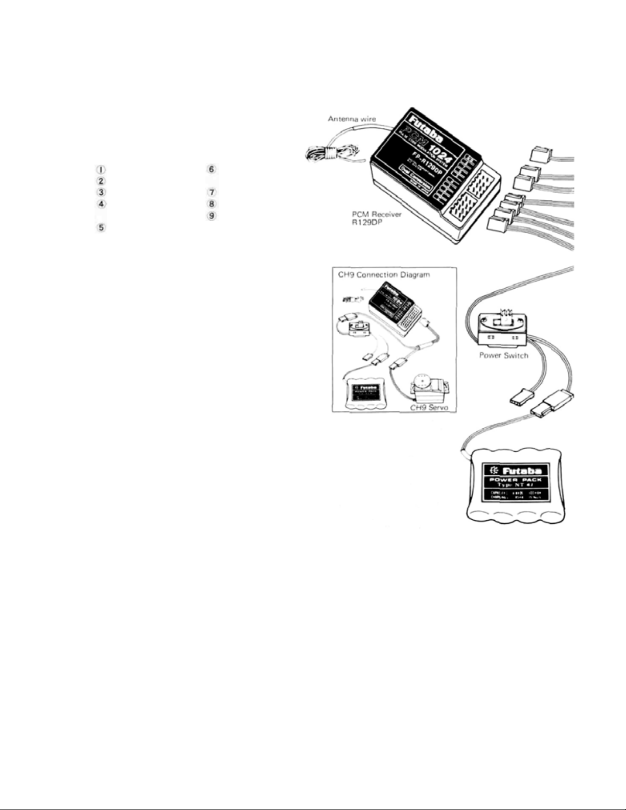
•RECEIVER AND
SERVOS
Receiver, servo, switch, and battery connections
The channel order is :
AIL Aileron
ELV Elevator
THR Throttle
RUD Rudder
(Tail rotor)
GER Retract gear
(Rate gyro
output
switching)
PRECAUTIONS
•Connect
etc. as shown in the figure. Extend the transmitter and receiver antennas to their full
length. Turn on the transmitter power switch,
then turn on the receiver power switch. The
servos will go to their neutral position. Move
the transmitter sticks one at a time to check
that each servo follows its control stick movement.
•Connect pushrods and linkages to the servos
and check that the direction of travel of each
servo matches the direction of movement of its
control stick. If a servo does not move in the
proper direction, use the servo reversing function
•
Operate
for binding and/or excess slop in the linkage or
pushrod. Unreasonable force on the servo arm
may damage
teries very quickly.
• Adjust servo output arms and aircraft control
linkage as necessary so that each servo moves
smoothly throughout its full range of travel,
even when the control stick and trim lever are
operated simultaneously in the same direction.
•Bealert for possible sources of electrical noise.
This set is noise-resistant,
less
•When
that the switch can move smoothly, to its full
extent in each direction without binding.
Install the switch where it wil l not be exposed
to engine oil, dust, dirt, etc. The switch can be
installed inside the fuselage and operated from
the outside with a piece of wire.
•
Do NOT shorten the
back along its length.
•When installing the servos, tighten the mount-
ing screws so that the rubber grommets
compressed
(See
parts
is
installing
the
receiver,
page
14).
each
servo
to
the
servo and
recommended.
the
switch
slightly.
If
PIT Pitch
AUX1 Accessory 1
AUX2 Accessory 2
CH9 Channel 9
servos,
its
receiver
switch
full
extent,
will
but the use of noise-
harness,
antenna or
the
screws
(Collective)
harness,
and check
drain
make sure
are
too
the
bat-
fold
tight,
it
are
the vibration-dampening
effect of the grommets
will be lost and servo
damage may occur.
• The crystal can be changed
without opening the receiver
case. Always use a Futaba
matched TX/RX crystal se t
to change frequencies.
• Extra servo output ar ms are
supplied.Use them as needed.
• Use extension cords where necessary. RF
"chokes" are not required with the PCM
receiver.
• Wrap the receiver and the airborne battery
pack separately in foam padding. Padding
should be wrapped loosely for maximum vibration
protection.
plastic bag and secure the end of the bag with a
rubber band.
• Use the rubber bands wrapped around the
receiver to hold the servo and s witc h leads.
•After installation and adjustments are complete, perform a range check by collapsing the
transmitter antenna and extending the receiver
to its full length and operating the transmitter
from a distance of 60 to 90 feet from the
receiver (aircraft). The system should operate
normally at this range.
[4]
Place
each
inside a waterproof
Page 7
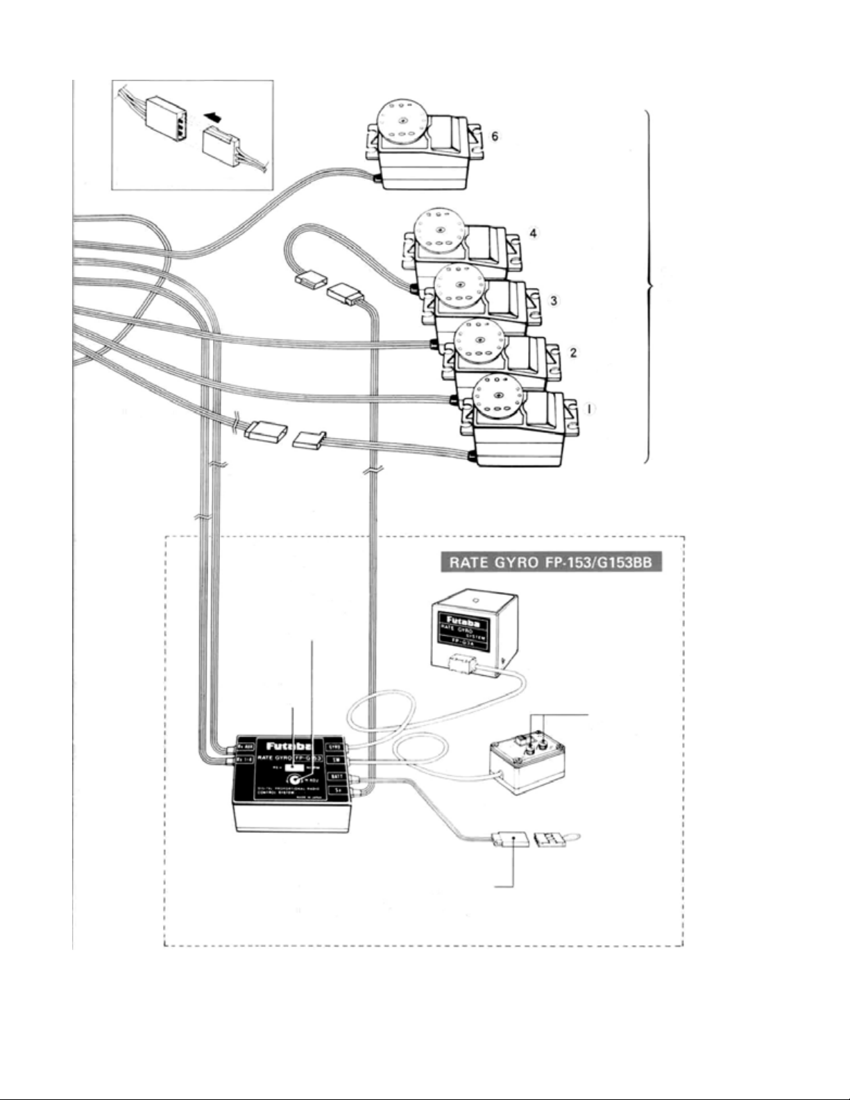
Pay careful
attention to connector polarity
Pitch Servo
(Collective)
Rudder (Tail rotor)
Servo
5 servos
supplied as
standard
Throttle Servo
Elevator Servo
Extension
cord
Aileron
Servo
Gear
(Rate Gyro
Output Switching)
Servo Neutral Trimmer
(rudder servo for
helicopter)
(This trimmer is
operative even when
the gyro control box
power switch is
turned OFF.)
Gyro
Gyro output
reversing switch
Gyro
sensitivity
adjustment
trimmers
Gyro Control Box
Control Amplifier
Connector for 6V pack of five batteries
Motor Regulator Power Supply
(Insert t he jumper connector when
power supply shared w/ RX.)
Jumper Connector
Page 8
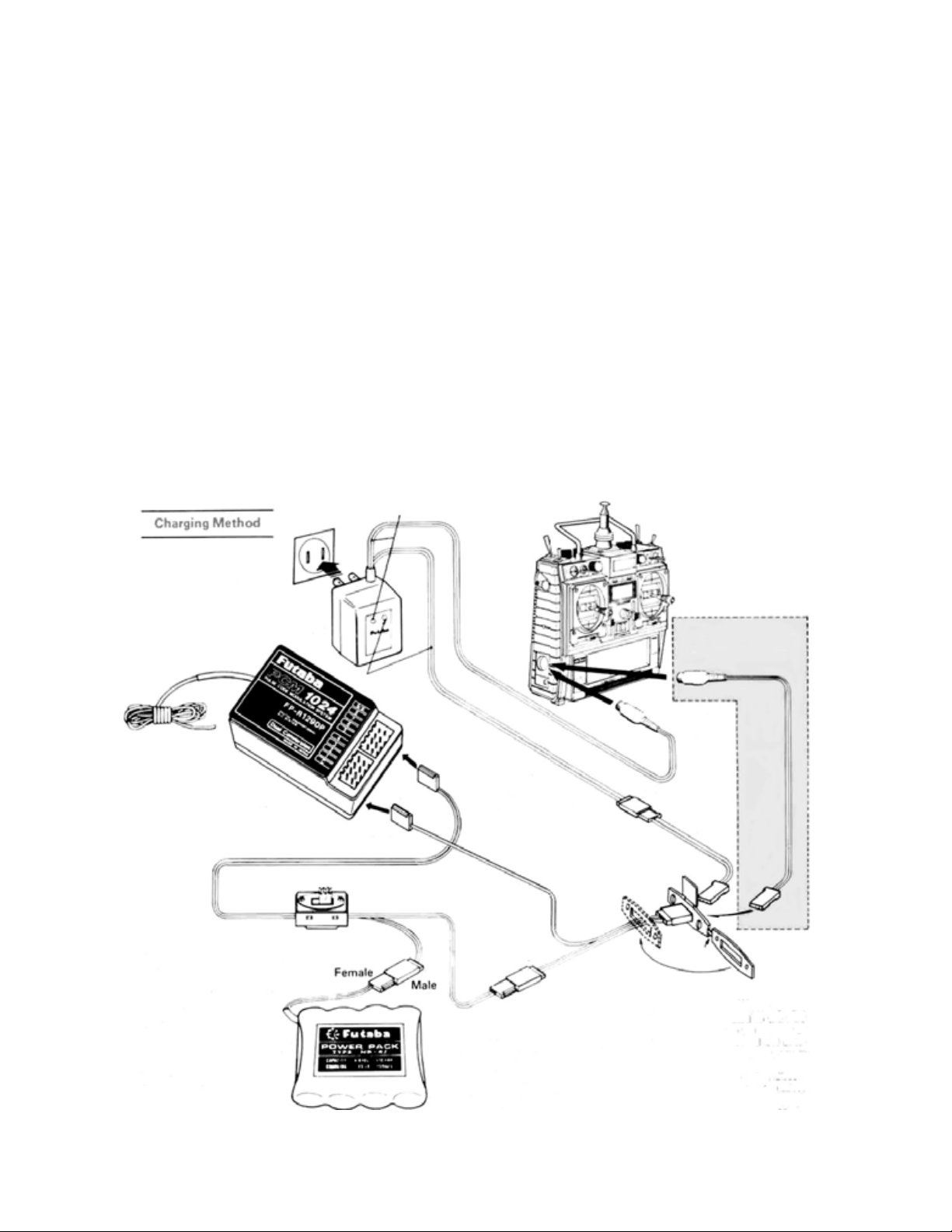
BATTERY
CHARGING
INSTRUCTIONS
(Transmitter
and
Receiver
Before operating your system, recharge the Nicd batteries as follows:
Nicd
Batteries)
• Connect the DIN connector of the FBC-6B (2)
battery charger to the transmitter charging
socket, and connect the 3P connector to the
airborne NR-4LB Nicd battery pack and plug
the battery charger into a 120VAC outlet as
shown in the figure.
•The
TX
and
RX
LEDs
light
to
show
that batteries are being charged. The Nicd batteries can
also be charged through the DSC-CHG cord by
connecting the CHG adaptor to the charger as
shown in the figure. This allows the NR-4LB
airborne Nicd pack to be charged without
removing it from the model.
•Normally recharge the battery for about 15
hours. If it has not been used for some time,
discharge and recharge it two or three times,
,TX (transmitter)
AC-120V
Charger FBC-6B (2)
RX (receiver)
then charge it a full 15 hours.
• The amount of operating time before the batteries must be recharged can be estimated by
checking the integrated timer at the moment
the TX battery alarm sounds (antenna extended).
• Leaving batteries in the discharged state for a
long time will adversely affect their capacity
and life.
• The TX and RX Nicd batteries can be charged
simultaneously or independently.
• A fully-charged TX battery can be used for
about 10 flights of 10 minutes each. The air borne NR-4LB Nicd battery pack can be used
for about 7 flights when 5 servos ar e used.
Make this connection
when using the DSC.
DSC cord
Charging
socket
and
DSC
connector
Receiver
• When the
DSC
cord
is connected, the receiver
power supply voltage
is measured
(no load).
The voltage is displayed
bv "Ex" on the lower
right
side
of the
initial
LCD screen.
Female
NR-4J
Female
Install the accessory
DSC-CHG cord
(connector w ith tab)
to the side of
the aircraft fuselage
to use th e charging
and DSC socket.
DSC-CHG cord
Male
Female
• The DSC (Direct Servo Controller)
system connects the signals from
the transmitter directly to terminal
C of the receiver through the DSC
cord and controls the servos without transmitting radio waves. It is
extremely convenient when other
flyers are on the same frequency,
[6]
Male
Female
CHG
Adaptor
Female
Male
Cut here.
or during contests, etc.
•When the DIN connector of the
DSC cord is connected to the DSC
socket, the power to the encoder of
the transmitter is turned ON automatically. The transmitter power
switch is left OFF.
• When not using the DSC, disconnect the DIN connector to reduce
battery drain.
• To operate the servos, turn on the
airborne switch, (only)
Female
Page 9
•BASIC TRANSMITTER T9VHP CONTROLS
Refer to the fold-out illustration at the back of the manual.
Aileron Control (Right and Left Cyclic on
helicopter)
Elevator Control (Fore and Aft Cyclic on
helicopter)
Throttle Control (Throttle and Collective
Pitch (T/C) on helicopter)
Rudder Control (Tail rotor on helicopter)
CH5 Switch Multiple uses depending on programming by modeler.
• Landing Gear (fixed wing aircraft)
• Rate gyro output sensitivity switching (helicopter)
•COMBI Switch - Rudder offset, Idle-Up.
and Dual rate can be turned ON and
OFF.
• Inverted flight switch
Hovering Pitch
Lever — left side of transmitter
CH6 Control Lever (In BASIC mixing mode)
Throw can be adjusted within this range
with the lever when the throttle stick is in
the neutral position.
Pitch control servo
total travel
CH7 Control Knob Pitch Trim Knob (If function
activated)
CH8 Control Switch COMBI Switch (if selected) - RUD offset, Idle-Up, and D/R ON/
OFF
Aileron Trim Lever
Elevator Trim Lever
Throttle (ATL) Trim Lev e r
Aileron Dual Rate ON/OFF Switch
Elevator Dual Rate ON/OFF Switch
Rudder Dual Rate ON/OFF Switch
NOTE: Functions of the D/R switches can
be selected, combined, ON/OFF directions
changed, etc. (See
page 46)
Revolution Mixing (Pitch ->• Rudder Mixing)
UP Side Knob
Revolution Mixing (Pitch -> Rudder Mixing)
DOWN Side Knob
Idle-up 1 ON/OFF Switch
Idle-up 1 Knob
Idle-up 2 ON/OFF Switch
Idle-up 2 Knob
Hovering Throttle Trim Knob
Throttle Hold Switch
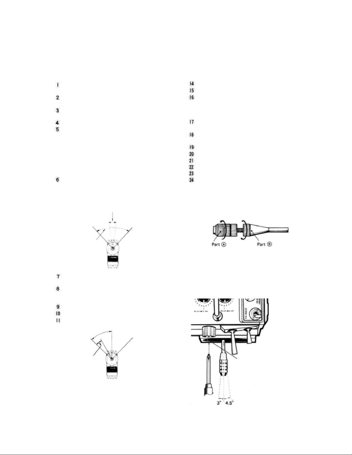
Non-Slip Adjustable Control Sticks
The length of the control sticks can be adjusted to suit operator preference.
Unlock
Parts A andB
posite directions as indicated by the arrows,
and adjust the control stick to the most comfortable length.
by turning them in op-
Adjustable Stick Angle
The horizontal angle of the control sticks
can be adjusted.
LOW
Servo travel by
throttle trimming
12 Rudder Trim Lever
13 High Pitch
Trim
mitter
HIGH
Lever
— right side of trans-
[7]
Phillips
Screwdriver
Turn this screw with a
Phillips screwdriver.
The open gimbal stick angle
can be adjusted from about
3° to the inside to 4.5° to
the outside by turning the
adjusting screw as shown.
Adjust the control stick to
the most comfortable angle.
Page 10

Transmitter RF Module
To remove the module, pull
the module outward while
pushing tabs toward the
center.
Transmitter crystal.
To
switch a frequency in
the same band, change
this crystal.
72MHz Band
53MHz Band
50MHz Band
Transmitter Battery Pack Replacement
and Spare Crystal Holder
Remove
battery
box
cover.
Lift
out
the
Nicd battery pack and disconnect the con-
nector.
the
A temperature
use is normal.
rise in the RF module during
Mini Stand
Use this fold-out Mini Stand as shown when
laying the transmitter down. This makes
operation easier and protects the transmitter
and module.
Spare crystal holders
NOTE: Be careful not to drop the Nicd battery
pack.
Opening Trimmer Panel and Key Cover
Flip up with the tab
NOTE: Flip up at both sides with your
fingers. Do not try to open the
panel at the center. The cover may
be damaged.
[8]
Page 11

Screen contrast adjustment
Adjust the screen contrast with the special
screwdriver provided. The contrast increases
when the adjusting screw is turned clockwise.
Monitor Lamps Sub-trimmers do not operate unless the pertinent
Functions of Sub-Trimmers
Sub-trimmers are located on the front panel to
allow convenient trimming of programmed set tings on the field or during flight. Master the
computer functions before using them.
T
H. HOLD Throttle hold (TH. servo)
position adjustment
RUD.OFFSET Rudder offset adjustment
NOR.PI.LO
IDL.UP1PI.LO Idle-up 1 low pitch adjust-
IDL.UP2PI.LO Idle-up 2 low pitch adjust-
HOLD Pl.LO.
RUD. -> THR. Rudder -> throttle mixing
HOLD.PI.HI. Hold pitch high side adjust-
function is set to
Normal pitch low side ad-
justment
ment
ment
Hold pitch low side adjust-
ment
adjustment
ment
The POWER Lamp lights when the transmitter power is turned ON.
The ALARM LED Lamp at the right:
• Blinks off once per
Safe data tr ansmission.
• Blinks on and off when an activated mix-
ing switch is ON (T. Hold, Idle-up, Invert)
• Lights steadily at all other times.
minute during Fail
[9]
Page 12

ADJUSTMENTS AND FLIGHT TECHNIQUES
•OPERATING INSTRUCTIONS.
• When adjusting and setting the transmitter functions, connect the receiver and servos, and
make the adjustments while observing the operation of the servos.
• Alternatively, when studying the operation of transmitter functions, remove the transmitter RF module (to reduce battery drain). The effects of adjustments can be viewed on th e
SRV program screen (See page 50).
• Set the power switch to the ON position. The standard screen shown below appears on the
LCD display.
TIMER RESET KEYS
TACHOMETER
•Tx 10.1V Transmitter Voltage
• Ex 0.0V The receiver battery voltage can be measured by using the DSC cord supplied.
Pressing bot h keys simultaneously,
resets the integrating timer.
Display will read 0:00:00.
Integrating Timer display
TIMER
The TIMER function can be used to monitor flying time, fuel consumption, at contests,
etc. Four different timing functions are available: Up Timer, Down Timer, Rhythmic Timer,
and Total (Integrating) Timer.
Timer Functions
1) Up Timer This timer counts up from zero in
1 second steps. Its maximum count is 59:59.
When the alarm time is set, a buzzer begins to
sound 10 seconds before the set time is up.
The buzzer also sounds at each 1 minute
interval. When th e time reaches 59:59, timing
restarts from 00:00.
2) Down Timer This timer counts down from
the set time in 1 second steps. Operation is
otherwise the same as the Up Timer.
3) Rhythmic Timer This is a 0.1 second cyclic
timer. A buzzer sounds at each set alarm
interval. When the set alarm interval elapses,
the counting automatically restarts.
4) Total (Integrating) Timer This timer records
the total transmitter O N time. It is very useful
for estimating remaining Nicd battery capac-
ity and monitoring total flying time. Maxi-
mum count is 59:59:59.
[10]
Page 13

Setting Instructions
1) Display the standard screen.
2) Reset the Total Timer by pressing the two
3)
Press
the
TIM
key. The TIMER program
played first.
4) Select the UP (Up), DN (Down), or RYT (Rhythmic) timer mode by pressing the
program key. The exa mp le shown is for the Up Timer.
5) To set the alarm time, switch to the TIMER SET display by pressing the SET key. Move the cursor to
the timer mode to be set usinq the
Set the alarm time with the program keys.
RES
program keys simultaneously.
screen
will
appear on the display. The
Up
Timer
cursor keys. Pressing the
will
be dis-
key will
When time and alarm setting is complete, return to the TIMER display by pressing the program key.
6) To start the timer, press the STA program key. The program key characters change to .When
the key is pressed, the timer stops.
7) When the program key is pressed, the display returns to the standard screen.
Timer Counting Range 1. UP/DN Tim ers 55min.59sec.
2. Total Timer 55 hrs. 59 min. 59 sec.
3. Rhythmic Timer 0.5 sec. to 59.9 sec. interval
[11]
Page 14

ADJUSTMENTS AND FLIGHT TECHNIQUES
TACHO METER
Tachometer
The tachometer function is used to measure the speed on one to five-bladed propellers, etc.
Speed (rpm) is measured up to a maximum of 50,000 rpm fin 20 rpm increments).
Setting Method
1) Display the standard screen, and press the
program key.
2) Press program key to to select the
number of blades.
Ex: for a two-bladed propeller.
Measure
3)
sensor on the transmitter (center of the left
the speed by pointing
the
built-in
Low Battery Warning
side panel) at the front or rear of the propeller
disc from a distance of 8 to 12 inches. Be sure
the model is restrained by an assistant, and be
very careful of the rotating propeller.
Allow a few seconds for the display to stabilize, then read the measured value. Maximum
speed range is 50,000 rpm.
This function operates when the transmitter
Nicd battery voltage drops below 8.5 volts. The
characters "LOW BATTERY" blink on the
screen, and a buzzer sounds. When this occurs,
land immediately and recharge or replace the
Nicd battery pack.
[12]
Page 15

Back Up Warning
When the stored data is lost, the characters
"BACK UP" blink on the screen and a buzzer
sounds. When the power switch is turned on
again, the error display disappears and all the
settings return to the factory-set values. When a
Back Up error occurs, the back-up lithium battery is probably dead, or there is trouble in the
system. To locate the cause, call your Futaba
service center. The back up lithium battery life
depends on the usage state, but is about 5 years.
SYSTEM PROGRAMMING
Press the EDIT program key of the standard screen.
Reversing
Fail Safe
Adjustable
Travel Volume
Adjustable
Function Rate
Dual Rate
Pressing the (EDIT) program key of the
standard
display the
EDIT
or
"Menu"
screen
will
screen. The cursor keys can be and
used to move the cursor bar to Line 1, 2, or 3 of
the screen. The program keys are used to select
System functions are programmed
and adjusted by using the LCD
display screen, the five DATA
INPUT (Program) keys, and the
End
(Returns to
preceding screen)
four CURSOR keys.
the desired programminq screen to be displayed.
NOTE: At all times, pressing the program
key will return the display to the next previous
screen. To return to the standard screen, just
keep pressing the key.
[13]
Page 16

ADJUSTMENTS AND FLIGHT TECHNIQUES
REVERSE
Servo Reversing
This
function
is
used
to
change
the
direction
of
servo
operation
or /ever movement.
Setting Method
1) Select the EDIT screen, the select the REVERSE screen by pressing the
key. to REVERSE.
2) Select the desired channel with the
cursor keys.
3) Select NORMAL or REVERSE operation by
program
and
pressing the
In the display example,
4) Return to the EDIT screen by pressing the
program key.
in
relation
or
to control
program key.
(Rudder) is set
stick
FAIL SAFE
Fail Safe
Fail Safe and Hold Functions
The HOLD (Hold) and F/S (Failsafe) functions
are designed to allow the aircraft or helicopter to
"fly
through" a momentary
strong interference, rather than experiencing the
familiar
"glitch"
the unwanted signal. These functions cannot be
expected to prevent a crash however, if the
normal signal interruption is of sufficient duration.
The HOLD function stops the servo at the position held just before the normal signal is lost.
When a normal signal is again received, the Hold
function is released.
The FAILSAFE
neutral or a pre-set position when the normal
signal is interrupted for 1 second or longer (The
system will remain in HOLD for the first 1
second of signal loss). When a normal signal
resumes, FAILSAFE is released.
as
the
function
loss
servos
react
will
move a servo
of
signal
or very
violently
to
to
BFS (Battery Fail Safe) Function
The BFS function moves the throttle (CH3)
servo to the pre-set Fail Safe position when the
airborne power supply is nearly exhausted. If no
Fail Safe position has been set, the throttle servo
will move to medium slow (neutral).
BFS can be released by lowering the throttle
Stick
past the
the CH9 switch. Throttle control is then regained
for about 30 seconds. At the end of 30 seconds,
will
BFS
move to the Fail Safe position. Whenever BFS
engages, land the aircraft as quickly as possible
and recharge or replace the Nicd battery pack.
release
re-engage
point
and
(adjustable),
the
throttle
[14]
will
or
with
again
Page 17

Fail Safe and Hold General Instructions
Fail Safe
• F/S or HOLD can be selected for each channel
(1
to
8).
•Channels
HOLD until a normal signal resumes. Those
selected for F/S will move to their pre-set positions after 1 second of signal interruption.
• F/S SET simultaneously stores the desired Fail
Safe position in the transmitter memory and
sends it to the receiver.
•The
receiver when the transmitter is first turned ON
and at one minute intervals as long as the transmitter is left on.
• The F/S position can be checked with the
• Only the Throttle channel (CH3) can be set for
Battery Fail Safe.
Fail Safe Setting
1) Display the EDIT screen, then select the
FAILSAFE screen by pressing the pro-
gram key.
2) Move the cursor to the desired channel with
the and cursor keys and select
HOLD
selected, the number 50 will appear below the
appropriate channel on the POSI-(%) line of
the FAILSAFE screen.
3) Store the Failsafe positions in the transmitter
memory by pressing the key while holding the st ick or lever of the channel being set
in the desired Failsafe position. Simultaneously, the data is also transmitted to the receiver
and is automatically re-transmitted at one
minute intervals.
selected
F/S data
program key.
or F/S f o r e a c h channel by pressing the
or program key. When Failsafe is
for
HOLD
is
automatically
will
remain
sent
to
in
the
Battery Fail Safe Setting
1) Set the Failsafe position on the throttle channel
(CH3) as described above. A position
slightly above the minimum engine idle
is recommended.
2) BFS Release Point Setting (When
designated as the release channel)
• Move the cursor to the B/FS-RESET line of
the FAILSAFE screen with the or
cursor key.
•
Select the BFS
or program key.
•Set the throttle stick to the desired BFS
release
point
key. This designates CH3 (Throttle) as the
release
channel and
point simultaneously.
3) To release BFS by the CH9 switch, press the
program key.
• BFS can be released by the CH9 switch only
when the switch is moved to the upper
position. If the CH9 switch is in the lower
position, BFS cannot be released.
• In the BFS release state, the characters 0%RESET are displayed on the B/FS-RESET
line of the FAI LSAFE screen.
4) If Battery Fail Safe is not desired, press the
program key (when the cursor is on the
B/FS-RESET line).
then be disabled.
In the example below, (Throttle) was set to
Fail Safe and Battery Fai l Safe.
release
and
The
channel
press
the program
sets
the
BFS
with
stick
function
speed
THR
the
release
will
is
[15]
Page 18

ADJUSTMENTS AND FLIGHT TECHNIQUES
ADJUSTABLE TRAVEL VOLUME
• The ATV function is used to adjust servo travel limits. Servo travel can be adjusted independently in each
direction from neutral. Adjustment from 30% to 110% of normal full travel (throw) is possible.
•
NOTE:
• ATV limits are displayed by a bar graph and numbers. The point at which the cursor moves fro m left to
Setting Method
1) Select the EDIT screen, then select the ATV
2) Rate data (endpoint limits) for Channels 1 to
3) Select the channel to be set with the and
4) Operate the control stick, lever, or switch of
When
servo
travel
is
changed
by
ATV,
the limits of
trim
throw
and the Dual
limits are increased or reduced by the same percentage.
right, as the stick or lever is moved, is the electrical neutral point of that channel.
extent in the desired direction. The cursor will
program screen by pressing the program
key.
automatically move to the left or right confirming the direction to be set.
5) Servo endpoint limits can be set by pressing
4 is displayed on the screen. To display and
adjust Channels 5 to 8, press the program
key. Rate data for Channels 5 to 8 will be
displayed.
the and program keys while holding
the appropriate stick or lever in the same
direction.
Pressing
the program key
return the set limit to 100%.
6) When you are finished, press the key to
cursor keys.
return to the EDIT screen.
the channel to be adjusted to its maximum
Rate
ON
(Low
Rate)
will
In the example shown, the CH1 (Aileron) right throw is reduced to 90%.
In the bar graph illustration below, the right
100%
hand throw is reduced to 50% of normal, while
the left hand throw is set to 100%. Note that on
the right side. Dual Rate ON (Low Rate) and
Trim throw limits are also reduced to 50% of
normal.
RIGHT
50%
ATV Limit = 50%
D/R Limit = 70% of ATV
Limit
TRIM Limit
NEUTRAL
LEFT
50%
100%
Normal (Full) Throw = 100%
TRIM Limit
D/R Limit = 70% of Full
Throw
[16]
Page 19

ADJUSTABLE FUNCTION RATE
AFR is a servo endpoint limiting function, similar to A TV with one exception:
AFR limits only the Dual Rate OFF (High-Rate) servo travel. Trim throw/and Dual Rate
ON (Low Rate) limits are unaffected (unless AFR is reduced below the D/R ON limit).
Setting Method
1) The setting method for AF R is the same as for ATV (See page 16).
2) Select the EDIT screen and press the AFR program key.
AFR Limit = 70 %
D/R Limit = 50% of Full
RIGHT
NEUTRAL
LEFT
NOTE: Trim Limits and D/R Limits same in both directions.
TRIM Limit
TRIM Limit
D/R Limit = 5 0%
Normal (Full) Throw = 100%
Throw
In
the bar graph illustration below, the right
hand throw is reduced to 70% of normal throw
by AFR. Note that the Dual Rate ON (Low
Rate) limit and Trim throw limits remain the
same
on
both
sides
(Compare
with the ATV
illustration on page 16).
[17]
Page 20

ADJUSTMENTS AND FLIGHT TECHNIQUES
DUAL RATE
Dual Rate functions allow the modeler to switch servo travel limits in flight, thus varying
the control sensitivity for different flight conditions or maneuvers.
• Dual Rate functions are available on CH1 (Aileron), CH2 (Elevator), and CH4 (Rudder/Tail Rotor).
• Dual Rate ON (Low Rate) limits can be adjusted from 30% to 100% of full throw.
•
If
servo
travel
is
reduced by ATV, the D/R ON throw will
D/R OFF). If AFR is used, the D/R ON limit is unaffected, and w ill be 30% to 110% of normal ( ful l)
throw.
• Dual Rate ON limits can be adjusted independently in each direction from neutral.
•There
•The
• In the AUTO D/R mode, the D/R functions can be turned ON and OFF according to the position
are
three D/R ON/OFF
switches in any combination the modeler desires, or D/R functions can be switched ON and OFF auto-
matically according to the position of the Throttle/Collective stick.
ON/OFF directions
(See page 46).
(adjustable) of the T/C stick.
Switches.
of
the D/R switches
Control of the
can
be
be
three
reversed
30%
to
100% of the
D/R functions
using the PARAMETERS program
can
limit
be
assigned
set
by
ATV
to
these
screen
(in
Settinq Method
1) Select the EDIT screen, then sele ct the DUAL
RATE screen with the program key.
2) Select the channel to be set with the or
cursor key.
3) Move the cursor to the position with the
or cursor key and press the or
program key to activate or deactivate th e
D/R function for that channel.
When
the
4)
will be displayed in the "INH" position, depending upon the position of the pertinent
D/R ON/OFF Switch.
5) Using th e and
cursor to the L/D or R/U position and set
the desired D/R ON throw with the or
key will returen the set limit to 100%.
6) Select the desired ON/OFF Switch for each
D/R function by moving the cursor to the
"sw" position with the
selecting Switch No.
key
program keys. Pressing the program
is
pressed,
"ON"or
cursor keys, move the
key and or
1, 2, or 3 with the
"OFF"
, or program key.
The D/R ON/OFF Switches are designated by
numbers as follows:
1 ... Aileron D/R
2 ... Elevator D/R
3... Rudder D/R
Each switch may be used to control one, two, or
all three D/R functions as desired.
7) D/R may also be switched ON and OFF in
conjunction with other functions (Idle-up,
etc.) using the COMBI SW function of the
PARAMETER program screen (See page 46).
As designated on the
transmitter front.
[18]
Page 21

Auto Dual Rate
• Dual Rate functions may be switched ON and
OFF automatically, according to the Throttle
(CH3) control stick position.
1) Move the cursor to the "mode" position with
the or cursor key.
2 Use the or cursor key to select the
D/R function to be set to AUTO and press the
program key.
3) Use the and
the cursor to "pos".
4)
Set the Throttle stick at the point you w ish
ON/OFF switching to occur, and press the
program key.
5) When the Throttle stick is below the ON/OFF
switching point and the pertinent D/R ON/
cursor keys to move
OFF Switch is set to OFF, Dual Rate will be
OFF.
• If the assigned D/R ON/OFF Switch is set
to
ON, then D/R
Throttle stick is still below the ON/OFF
point.
6) When the Throttle stick is moved above the
ON/OFF point, then D/R will be ON, regardless of the position of the D/R ON/OFF
Switch.
NOTE: Dual Rate ON/OFF Switch directions
can be reversed using the PARAMETER program
screen (See D/R SW DIR page 46).
will
be
ON
even
if
the
In the example shown, the AIL Dual Rate function will be switched to D/R ON ( Low Rate) when the
Throttle stick is moved above the 10% positon. AI L and RUD D/R functions are both set to Switch No. 3.
End Soft Key
Press the program key to return to the EDIT screen.
[19]
Page 22

ADJUSTMENTS AND FLIGHT TECHNIQUES
Select the EDIT screen, and move the cursor to Line 2 with the or
Exponential Mixing Trim Parameter Model End
cursor key.
EXPONENTIAL/VTR
Exponential or VTR functions can be used to change the servo response curve from the
normal Iinear operation. This can be very helpful if control response is either sluggish or too
sensitive near the neutral position. Maximum servo deflection limits (set by ATV and/or
AFR) remain the same.
Exponential
•With
Exponential
movement in relation to a given amount of
control stick deflection can be made to steadily
increase (or decrease) as the stick is moved
farther from neutral (or as in the case of CH3
(Throttle), from one extreme to the other).
• Exponential control is available on CH1 to
CH8.
•Two
different
curves can be selected.
The TYPE 1 Curve is symmetrical in both
directions from neutral. This type is generally
control, the amount of
types of
Exponential
servo
response
used, when desired, on "neutralizing" controls
such as AI L, ELEV. and RUD.
The TYPE 2 Curve is exponential in one direction over the full stroke of the control stick or
lever. This type is normally used w ith functions
such as T HR .
• The amount of exponential can be varied from
0% to 100% in 4% steps. By using positive or
negative exponential with either the TYPE 1 or
TYPE 2 EXPO Curves, a total of four different
types of Exponential control response can be
selected.
Page 23

TYPE 1 Positive
TYPE 2 Positive
With this type of curve, control response will be made
more sensitive near neutral and less sensitive as the stick
is deflected farther towards its extreme limits.
TYPE 1 Negative
With this type of curve, control response will be
"softer" around neutral and increase as the stick is
deflected farther.
• When V TR is used, servo response remains linear, but the response is automatically switched to a higher
rate at a ce rtain (adjustable) point in the control stick deflection.
• The i nit ial response rate is the same as the Dual Rate ON rate (See page 18).
• Maximum servo travel limit is still controlled by ATV and/or AFR.
Setting Methods
Exponential
1) Select the EDIT screen and move the cursor
to Line 2 with the or
Select the EXPONENTIAL/VTR program
screen by pressing the program key.
2) Select the channel to be set with the or
cursor key, then select the operation
mode with the or program
key. VTR is available only on CH1, CH2, and
CH4.
3) When the EXP mode is selected, the type of
curve can be selected by moving the cursor
to the "typ" position with the or
cursor key and pressing the or
gram key. (The type of curve is not selected
in the VT R mode.)
4) When the EXP or VTR mode is selected, the
servo response curve is displayed on a graph
at the right side of the screen. The amount of
Expo can be changed by moving the cursor to
cursor key.
pro
With this type of curve, response will be most sensitive
at the LOW end of control stick travel, and decrease as
the stick is moved toward HIGH.
TYPE 2 Negative
H
VTR Variable Trace Ratio
With this curve, the response is less at the LOW end and
steadily increases as the stick is moved toward HIGH.
the "rate" position and pressing the or
program key. When the 0 program
key is pressed, the rate is preset to 0% (0% =
normal or linear).
5) In the V TR mode, the "rate" adjustment is
used to adjust the stick position at which the
servo response changes from Low to High.
The initial (Low) rate is adjusted by the D/R
adjustment program (See page 18).
6) Channels 5 through 8 can be displayed and set
by pressing the program key.
In the above example, a TYPE 2 Negative Exponential Curve is shown. This type is often
helpful on the Throttle channel. Depending on
the carburetor design and linkage, actual power
transition can be made more linear in relation to
stick movement. (About —20% is a good initial
setting for fixed-wing aircraft).
Page 24

ADJUSTMENTS AND FLIGHT TECHNIQUES
MIXING
• Mixing allows two or more channels to be controlled by a single transmitter control stick or lever. This set
features Programmable Mi xing with four independent mixing circuits, along with special built-in mixing
circuits.
• NOTE: Only PROG-MIX Programable Mixing can be used in the BASIC Parameter mode. (See PARA-
METER, page 46).
•There are five types of mixing (including Prog. Mixing).
1: PROG MIX
Programmable Mixing
4: SWASH-MODE
Swashplate Mixing
1) Select the EDIT screen and move the cursor
to Line 2 with the cursor key, then press
the program key.
2) to can be selected with the program to
keys.
2: PITCH-MIX
Pitch Mixing
5: THROTTLE-MIX
Throttle Mixing
3: RUDDER-MIX
Rudder Mixing
3) To use 1:PROG-MIX, press the program
key. The PROGRAMABLE
be displayed.
MIX
screen
will
Page 25

PROGRAMABLE MIX
Programmable Mixing
Four separate Programmable Mixing circuits allow almost infinite mixing combinations. The
features of this program provide the modeler with unlimited versatility in trimming and
controlling complex, high-performance models.
• Mixing of any two channels is possible.
• Four completely independent mixing
circuits
are available.
• Mix in g amounts can be adjusted independently
in either direction from neutral or offset point.
•The
PROG-MIX
ON/OFF
Switch
can
be
selected.
•The point at which the mixing direction reverses is fully-adjustable.
•PROG-MIX circuits can be mixed with or
"slaved" to built-in mixing functions.
Slave Channel
+ and - indicate the
Master Channel
direction of mixing
•PROG-MIX circuits can be mixed with each
other.
•Trim
corrections
be added to the slave channel or not, as desired.
• Bi-directional mixing can be accomplished
using two mixing circuits (Ex: Flapperons)
•Adverse coupling of control inputs in fixedwing aircraft can be eliminated. (Ex: Tendency
to roll when rudder is applied in knife-edge
flight.)
Operation (Mixing) Amount
on the "Master"
When ON, the trim inputs to the
"Master" channel are also mixed
to the "Slave" channel. When
OFF,trim on the "Master"
channel affects the "Master"
channel only.
channel
can
When the SET program
key is pressed, the
CHANNEL SETTING
screen is displayed.
Mixing Circuit Number
Circuit is usable when set
to
ON
Switch Mode (ON/OFF
Switch Selection)
Indicates the control stick
position that the mixing
— reference point (R/L or
U/D Direction Change
Point) is offset to.
1. Always ON
2. ELEV.D/R Switch
3. RUD.D/R CH9 Switch
4. I DL E UP 1 a nd 2 (B ot h
switches must be ON)
5. GEAR (CH5)
Page 26

ADJUSTMENTS AND FLIGHT TECHNIQUES
Master and Slave Channel Selection
In the first example shown, THR (Throttle) is set at "mas". The Master channel can be changed by pressing
the or
program key.
The cursor can be moved to the "slv" position with the
selected by pressing the or
Master Channel Setting
1) Select the PROG-MIX screen as described on
page 22.
2) Select the CHANNEL SETTING screen
pressing the SET program key.
3) The Master channel can be set
or program key to change the
channel.
4) The mixin q circuit to be programmed can be
selected
or cursor key.
1) Move the cursor to the "slv" position with the
2) Select the
proqram key. In the example above, the Slave
channel on (Mixing Circuit No. 1) is set
to
by moving
or cursor key.
Slave
AIL.
the
channel
cursor
with
program key.
by pressing the
with
the
the or
by
[24]
or
Programmable mixing circuits can be combined
with each other, or with built-in mixing circuits
by two methods.
1) Setting a Mixing Circuit No. in the "mas"
position (MX1, MX2, MX3, or MX4).
2) and setting.
Depending upon which channels are selected on
different mixing circuits, MX1, MX2, MX3, or
MX4 can be displayed in the "mas" position. The
slave channel of the mixing number displayed in
the "mas" column, then.becomes a Master channel on the mixing circuit line that it is displayed
and the two ci rc uits are connected.
cursor key and the Slave channel
Combination of Mixing Circuits
Mixing Number Method
Page 27

and
1) are displayed when the cursor is in
the "mas" position. are displayed
when the cursor is in the "slv" position.
Method
Displayed when cursor is in "mas"
position.
Indicates that Master channel is
"slaved" to another circuit.
2) To activate XON or YON mixing, press the
or key, The character will
appear next to the appropriate channel on the
left side of the screen to indicate that or
has been set.
•Combinations allow more efficient use of
the number of mixing circuits. An example
is shown below.
When are not used, three circuits and
are required for the mixing program shown
below. Programmable mixing is performed from
Aileron to Elevator and Rudder, and from Elevator to Rudder. This is the same as A IL -> ELV ->
RUD
mixing.
The same mixing program as in Example 1 can be
set up us ing onl y tw o 2 mixing circuits when the
and functions are used.
MX 1 is set t o A I L -> ELV mixing.
MX 2 is set to ELV -> RUD mixing.
The cursor is moved to the MX1 "slv" position,
and is set. The cursor is then moved to the
"mas" position and is set. MX3 is turned
OFF
(Set
to
This is also the equivalent of AIL -> ELV -> RUD
mixing.
Setting MX1 as the MX2 Master channel in the
example is the same as setting
• Combinations are effective when the number
of mixing circuits is insufficient, and when
PROG-MIX circuits are mixed with built-in
mixing circuits.
).
Page 28

ADJUSTMENTS AND FLIGHT TECHNIQUES
• Activation of Programmable Mixing Circuits
1) Move the cursor to the "INH" position with
the
2) To activate the circuit, press the key.
"ON" or "OFF" will be displayed according
The mixing rate setting determines the amount
of deflection of the Slave servo in relation to
movement of the Master channel control stick or
lever. Both th e amount (rate) and direction (+ or
-) of movement can be set independently, either
side of the mixing point (neutral).
1) Move the cursor to the R/U or L/D position
with the
2) Set the desired rate with the
3) The servo operating direction can be changed
with the and
Programmable Mixing can be designated as "al-
ways ON" or switched ON and OFF in flight by
any four different switches.
1) Move the c ur so r to the "sw" position with the
2) Press the appropriate program key (
through ) for the switch selection
sired.
Switch assignments are designated by numbers as
shown below:
1.
2.
3.
4.
5.
•
In
or
Mixing Rate and Direction Setting
cursor key. or
program key.
Mixing ON/OFF Switch Selection
or
Always ON
ELEV.D/R Switch
RUD.D/R CH9 Switch
IDLE UP 1 and 2 (Both switches must be ON)
Gear (CH5)
the
"Trim
cursor key.
program keys.
cursor key.
Trim ON/OFF Setting
ON"
mode.
trim
lever
inputs
de-
on
or
to the position of the designated Mixing ON/
OFF Switch.
3) To deactivate the mixinq circuit, press the
program key.
the Master channel will be "carried over" to
the Slave channel, causing a corresponding
change in the Slave channel neutral position
when the mixing is ON. In the "Trim OFF"
mode, trim changes to the Master channel
affect the master channel only, regardless of
the mixing ON/OFF switch position.
•Trim
ON/OFF
Master is a primary control stick (AIL, ELEV,
RUD.AND THR).
Setting Method
1) Move the cursor to the "trm" position with
selection
is
only relevant
if
the
the or cursor key.
2) Select the "Trim ON" or "Trim OFF" mode
with the or
Offset (Rate and Direction Change Point) Setting
• Normally, the neutral (center) position of the
Master channel control stick will be the point
at which the Slave channel servo rate and direction change occurs. This control stick position
can be changed (Offset) if desired.
1) Move the cursor to the "ofs" position with
the or c
2) Move the Master channel control stick to the
desired position at which you wish rate and
direction change of the Slave channel servo to
occur. (Mixing amount = 0 Point)
3) Press the key. The Master channel stick
position is memorized and will be displayed as
a percentage in the "ofs" position of the
screen. "+" indicates a stick position to the
R/U side of neutral. "-" indicates a position
to the L/D side of neutral. "0%" indicates
that the direction will change at the normal
control stick neutral position.
program key.
ursor key.
 Loading...