


USER / INSTALLATION MANUAL
MS-RA205
TRUE MARINE STEREO

PRECAUTIONS
Do not attempt to open the unit. There are no user serviceable parts or adjustment’s inside.
No responsibility can be taken for use of the unit other than under normally expected operating conditions.
If exposed to direct sunlight or operated for extended periods metal surfaces may become hot. Take care when handling.
USING iPod/iPhones
This unit has been tested with compatible authentic iPod models under normal expected operating conditions, free from any pre-existing defects in either the unit or the iPod.
No responsibility can be taken for use of the unit other than under normally expected operating conditions in conjunction with fully functional and undamaged iPod units which have been manufactured and authorized by Apple Inc.
USB Flash Drives
•Drive format: All USB flash drives used with this unit must be formatted to either FAT32 or NTFS format. These are the most commonly used format for USB flash drives.
•Audio track format: Audio tracks stored on USB flash drive must be in MP3, M4A or FLAC formats to play on this unit.
Care and Maintenance
As with all products exposed to the harsh marine environment, a little care will help preserve the finish. FUSION recommends that you clean any salt water and/ or salt residue from the stereo with a damp cloth soaked in fresh water.
Most marine Stereo’s have small vents in their cases to allow a way out for moisture that finds its way in. In some limited instances it is possible for moist air to be drawn into the vents when the air inside the Stereo cools down after it is turned off. Direct sunlight on the front can draw this moisture up against the Window, causing fogging. Turning on the Stereo will speed up moisture
removal. Fogging is not abnormal, nor will it harm your Stereo, which is built to withstand the harsh marine environment.
REGISTER YOUR PRODUCT ONLINE
For your own peace of mind, register your product purchase online at www.fusionelectronics.com
We’ll keep you up to date with any news related to your product or new accessories to help you get the most from your product.
RECORD YOUR PRODUCT DETAILS HERE:
SERIAL NUMBER |
|
DATE OF PURCHASE |
AFFIX RECEIPT HERE |
|
|
2

CONTENTS
INSTALLATION 4 WIRING DIAGRAM 7 CONNECTIONS 8 BUTTON DESCRIPTION 10 GENERAL OPERATION 12 RADIO OPERATION 16 USB OPERATION 17 AUX OPERATION 17 iPod/iPhone OPERATION 18 ANDROID (MTP) DEVICE OPERATION 19 BLUETOOTH OPERATION 20 SiriusXM Satellite Radio 22 ZONE OPERATION 23 ADDITIONAL FEATURES 24 MENU STRUCTURE 25 TROUBLESHOOTING 26 FUSION MARINE ACCESSORIES 28 SPECIFICATIONS AND LICENSING 30
3

INSTALLATION
If any modification to the vessel is required, such as drilling holes etc fusion recommends consultation with your boat dealer or manufacturer beforehand.
Create mounting hole for product and drill Screw Pilot Holes. Refer to mounting template included with product or download from www.fusionelectronics.com
•Fit mounting gasket
•Insert the unit into the mounting hole
•Use the supplied 4 x self tapping screws, to affix the unit into position.
•Attach screw covers
Note: Appropriate mounting is very important to ensure correct operation. Select a location that allows both free/open airflow around rear of chassis, whilst minimizing exposure to moisture. Allow adequate room at the rear of the unit for the cable looms (approx 2”) and underneath the unit (approx 2”) if using a SiriusXM tuner (USA Only).
|
Note: The head unit must not be mounted on more than a 45˚ angle |
45˚ |
from the horizontal plain. Failure to follow mounting restrictions |
could void your warranty. |
4

Mounting Hole
Screw Pilot Hole
Mounting Gasket 
Screw Covers 
5
ELECTRICAL WIRING
Caution: The MS-RA205 is designed for vessels with a 12V DC Negative ground electrical system
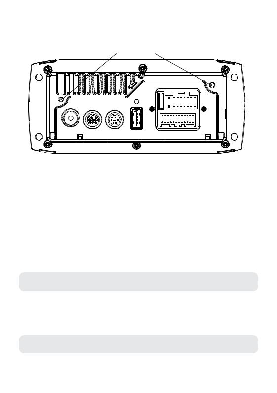
 Rear support holes
AERIAL SiriusXM REMOTE
USB
In some cases a rear support strap (not supplied) may be required. Please use the two holes indicated above, to attach the strap using two 8 gauge x 8mm self-tapping screws (not supplied).
INSTALLATION WARNING
•Ensure the marine vessels +12V lead is removed from the battery before any equipment is connected
•Investigate the marine vessels fuel tanks and electrical wiring locations before you begin installation
•Ensure all wiring is protected to avoid damage
When wiring the MS-RA205, ensure that the wires are away from sharp objects and that rubber grommets and insulated bungs are used when routing the wiring. Ensure that when connecting the wires to the speakers and audio system, the terminals and
connections are protected from shorting to each other.
Note: Ensure the antenna cable is routed away from any power cables, and is the minimal length, as long cable runs will affect AM reception performance.
For optimum radio reception please ensure you use a dedicated AM/FM ground independent marine antenna.
The use of a VHF splitter is not recommended as this will degrade your marine VHF radio performance.
Please refer to the following site for further info: www.pacificaerials.co.nz
Note: The head unit is IPx5 rated on the face when correctly bulkhead mounted. Failure to mount the head unit correctly may void your warranty.
6
Electrical Isolation of the MS-RA205
The MS-RA205 stereo has a metal chassis which is connected to the Ground / Negative / Black wire (like most other stereos).Extra care should be taken when installing this type of stereo in an aluminium boat (or boats with a conductive hull) if you require the electrical system to be isolated from the boat hull).
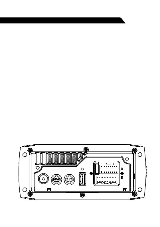
WIRING DIAGRAM
AERIAL SiriusXM REMOTE USB
A CABLE
YELLOW |
BATTERY (+12 V constant) |
|
|
RED |
IGNITION (+12V switched) |
|
|
BLACK |
GROUND (-12v) |
|
|
WHITE |
SPEAKER ZONE 1 L (+) |
|
|
WHITE/BLACK STRIPE |
SPEAKER ZONE 1 L (-) |
|
|
GREY |
SPEAKER ZONE 1 R (+) |
|
|
GREY/BLACK STRIPE |
SPEAKER ZONE 1 R (-) |
|
|
GREEN |
speaker ZONE 2 L (+) |
|
|
GREEN/BLACK STRIPE |
SPEAKER ZONE 2 L (-) |
|
|
PURPLE |
SPEAKER ZONE 2 R (+) |
|
|
PURPLE/BLACK STRIPE |
SPEAKER ZONE 2 R (-) |
|
|
BROWN |
DIM (+12V switched) |
|
|
BLUE/WHITE STRIPE |
AMPLIFIER ON |
|
|
BROWN/WHITE STRIPE |
TEL MUTE/INTERRUPT AUX |
|
|
B CABLE
WHITE RCA (Grey wire) |
AUX-IN (L) |
|
|
RED RCA (Grey wire) |
AUX-IN (R) |
|
|
ORANGE RCA (Black wire) |
SUB-OUT |
|
|
ORANGE RCA (Black wire) |
SUB-OUT |
|
|
WHITE RCA (Black wire) |
LINE-OUT ZONE 1 ( L) |
|
|
RED RCA (Black wire) |
LINE-OUT ZONE 1 (R) |
|
|
Note: Minimum speaker load impedance 4 Ohm
7
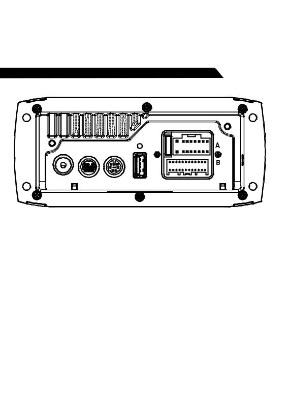
CONNECTIONS
CONNECTOR A
BATTERY +12VDC
Connect to the battery positive (+12VDC), or bus bars. A fuse or circuit breaker MUST be used at the battery end of the cable. Use a minimum wire size of 16AWG for wire length up to up to 6 meters / 20 feet.
IGNITION +12V switched
Connect to a separate switched +12V wire to control stereo ON/Off operation. Alternatively connect to the battery positive (+12VDC), or bus bars.
When the red “Accessory +12V switched” wire is not required for ignition on/off control, it MUST be connected together with the Yellow “Battery +12V” wire at the MS-RA205 head unit wiring loom.
Ground Wire — Recommended minimum wire size for Negative Ground wire: 16AWG for wire length up to up to 6 meters / 20 feet.
DIM — Connect to vessel lighting sytem to dim LCD and button illumination when vessel lights are turned on. When connecting the DIM input ensure the wire gauge used is suitable for the fuse supplying the circuit being connected to.
AMPLIFIER ON — When using an external amplifier connect to the “Remote turn ON” connection on the external amplifier.
TELE MUTE / INTERRUPT AUX — Connect to handsfree kit to either mute the stereo or switch to AUX to hear call. When this line is taken to ground the stereo is muted.
AERIAL SiriusXM REMOTE USB
8

CONNECTOR B
AUX INPUT — Connect an Auxiliary source to the left and right RCA (White = L, Red = R).
SUBWOOFER OUT (DUAL MONO) — Connect to a subwoofer amplifier, volume control linked to Zone 1. (Orange + Orange)
LINEOUT ZONE 1 — Connect to an amplifier, volume control linked to Zone 1. (White = L, Red = R).
ANTENNA CONNECTION — Connect an AM/FM marine antenna.
Note: Boat installations do not typically offer the best ground plane environment. For optimum performance a ground plane independent antenna is recommended.
USB/iPod/MTP CONNECTION — Connect a USB key / flash drive (not included), a FUSION Marine Uni-Dock (not included), a MTP device or a certified Apple iPod sync cable (not included).
Media Transfer Protocol (MTP): MTP is a standard developed for connecting media (music) devices over USB. It has been adopted on a number of platforms including Android. FUSION currently supports a range of smartphones utilising MTP.
Refer to www.fusionelectronics.com for the latest list of support devices.
SiriusXM SATELLITE RADIO (USA only) — (A) Connect to SiriusXM Connect Vehicle Tuner (not included) (For use in USA only) (B) Connect the MS-BT200 Bluetooth module (not included).
WIRED REMOTE / NMEA 2000 — Connect the MS-RA205 Stereo to a FUSION remote control network (cable supplied) or connect to an existing NMEA 2000 network with FUSION optional accessories (not supplied with Stereo):
MS-RA205 NMEA 2000 Drop Cable: CAB000863
FUSION NMEA 2000 T-Connector: CAB000581
Important Note: Adaptor cable CAB000862, provided with the MS-RA205 MUST not be used to connect the MS-RA205 to an existing NMEA 2000 network. Existing networks are normally powered separately. The non-powered drop cable (CAB000863) is available from FUSION for connecting to existing NMEA 2000 networks.
Note: FUSION recommends updating all remote(s) software via the MS-RA205 at time of installation to ensure compatibility. This can be done via the Update menu. Please refer to your remote manual for more information.
9
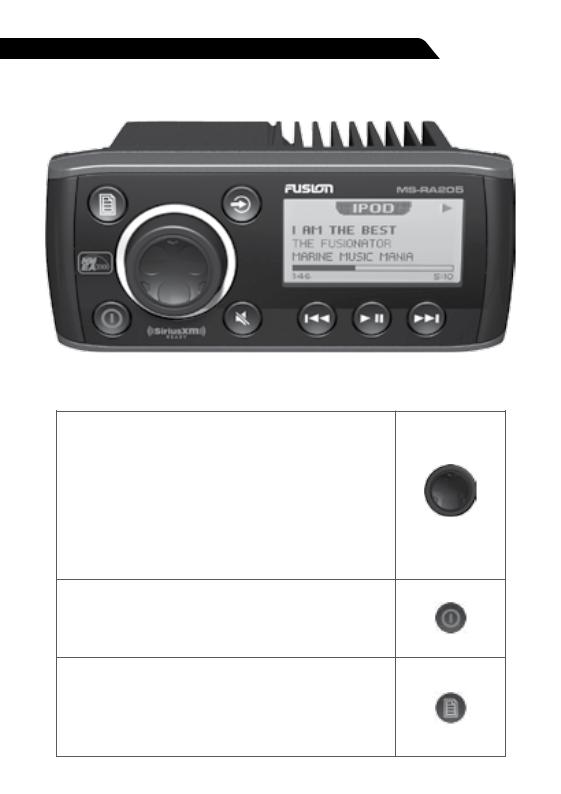
BUTTON DESCRIPTION
ROTARY ENCODER Turn
To adjust volume, move up or down a menu structure, or adjust a specific setting.
Press
To select a highlighted option, confirm a setting. Press to step through each zone for volume adjustment.
Press and Hold
For quick access to subwoofer level adjustment
POWER
Press to turn the unit ON/OFF.
Press and Hold
Press and hold for 10 seconds to ‘Reset’ the stereo.
MENU
Press to enter Menu System.
Press to return to previous screen.
Press and Hold
To exit the menu system.
10
 Loading...