


INTELPage IP 5
Contains Instructions For:
-Configuration
-Installation
-Operation
For v2.03 Unit Firmware, PLASTIC EDITION
(Manual Revision 2.10)
Last updated 15/01/2007
ACN 064 705 924
Australian Office |
United States Office |
|
PO Box 1037 |
8301 Cypress Plaza Drive, Suite 105 |
|
OPDC WA 6916 |
JACKSONVILLE, FLORIDA 32256-4416 |
|
AUSTRALIA |
UNITED STATES |
|
Phone +61 |
8 6240 0000 |
Phone +1 904 281 0073 |
Fax +61 |
8 6240 0001 |
Fax +1 904 281 0074 |
Email sales@commtechwireless.com |
Email sales@commtechwireless.com |
|
Web www.commtechwireless.com |
Web www.commtechwireless.com |
|

Fusion Intelpage IP |
Manual |
NOTICE
This manual, software and electronic circuitry are copyrighted. All rights reserved. Under the copyright laws, this manual, software and electronic circuitry may not be copied, in whole or in part without written prior consent of Commtech Wireless.
All information provided in this document is carefully prepared and offered in good faith as a guide in the installation, use and servicing of our products. Installers must ensure that the final installation operates satisfactorily within the relevant regulatory requirements. Commtech Wireless accepts no responsibility for incorrect installation. Commtech Wireless reserves the right to change products, specifications, and installation data at any time, without notice.
Commtech Wireless makes certain limited warranties with respect to defective diskettes, documentation and electronic circuitry. Please see the associated information contained on this page.
SOFTWARE LICENSE STATEMENT
This manual, software and electronic circuitry are protected by international copyright laws. Under the copyright laws, this manual, software and electronic circuitry may not be copied, in whole or in part without written prior consent of Commtech Wireless, except in the normal use of the software to make an archival copy of the software for the sole purpose of backing up the software and protecting your investment from loss or damage.
LIMITED WARRANTY
With respect to the physical documentation and physical electronic circuitry enclosed herein, Commtech Wireless warrants the same to be free of defects in materials and workmanship for a period of one year from the date of purchase. In the event of notification within the warranty period of defects in material or workmanship, Commtech Wireless will replace the defective diskettes, documentation and electronic circuitry. The remedy for breach of this warranty shall be limited to replacement and shall not encompass any other damages, including but not limited to loss of profit, and special, incidental, consequential, or other similar claims.
Commtech Wireless specifically disclaims all other warranties, expressed or implied, including but not limited to implied warranties of merchantability and fitness for a particular purpose with respect to defects in the documentation and electronic circuitry, and the program license granted herein, in particular, and without limiting operation of the program license with respect to any particular application, use, or purpose.
Page 2 |
© CommtechWireless |

Manual |
Fusion Intelpage IP |
COMPLIANCE NOTICES
SAA (AUSTRALIA)
To ensure compliance with ACA Technical Standards, this equipment is labeled with a Telecommunications Compliance Label. For safety reasons, this equipment should only be connected to compliant telecommunications equipment in accordance with the manufacturer’s instructions.
FCC (USA) Part 15
This equipment has been tested and found to comply with FCC Rules and Regulations, Part 15 with the limits of a Class B digital device, designed to provide reasonable protection against harmful interference. This equipment generates, uses and can radiate frequency energy and if not installed and used in accordance with the instructions, may cause interference harmful to radio communications. On the base of the equipment is a label containing an FCC Registration Number, if applicable.
Part 90
This equipment has been tested and found to comply with FCC Rules and Regulations, Part 90. FCCID: T5GPT5
IC (INDUSTRY CANADA, INDUSTRIE CANADA)
This class B digital apparatus complies with Canadian ICES-003. IC: 4767A-PT5
CE (EUROPE)
Commtech Wireless declare under our sole responsibility that the product Intelpage to which this declaration relates, is in conformity with the following standards and/or other normative documents.
-EN 300 224-2 v1.1.1 (2001-01)
-EN 55022: 1994 +A1: 1995 +A2: 1997
-EN 301 489 -2 v1.3.1 (2002-08)
-EN 60950-1: 2001
We hereby declare that all essential radio test suites have been carried out and that the above named product is in compliance to all the essential requirements of Directive 1999/5/EC.
The conformity assessment procedure referred to in Article 10(5) and detailed in Annex IV of Directive 1999/5/EC has been followed with the involvement of the following notified body:
Bay Area Compliance Laboratory Corporation, 1274 Anvilwood Ave., Sunnyvale, CA 94089, USA Identification mark: 1313 (Notified Body Number)
The equipment will also carry the class 2 equipment identifier (exclamation mark).
The technical documentation relevant to the above equipment can be made available for inspection on application to Commtech Wireless.
ROHS & WEEE
To minimize the environmental impact and take more responsibility to the earth we live, Commtech Wireless hereby confirms that the following product series comply with Directive 2002/95/EC (RoHS) and 2002/96/EC (WEEE)
of the European Parliament.
© CommtechWireless |
Page 3 |

Fusion Intelpage IP |
Manual |
SAFETY AND GENERAL INFORMATION
Important information on safe and efficient operation. Read this information before using the unit
Exposure To Radio Frequency Energy
Your Intelpage IP contains a low power radio transmitter. When it is ON, it transmits radio frequency (RF) energy.
Your Intelpage IP is designed to comply with the following national and international standards and guidelines regarding exposure of human beings to radio frequency electromagnetic energy (EME):
•United States Federal Communications Commission, Code of Regulations; 47 CFR part 2 sub-part J
•American National Standards Institute (ANSI) / Institute of Electrical and Electronic Engineers (IEEE) C95. 1- 1992
•Institute of Electrical and Electronic Engineers (IEEE) C95.1-1999 Edition
•National Council on Radiation Protection and Measurements (NCRP) of the United States, Report 86, 1986
•International Commission on Non-Ionizing Radiation Protection (ICNIRP) 1998
•National Radiological Protection Board of the United Kingdom 1995
•Ministry of Health (Canada) Safety Code 6. Limits of Human Exposure to Radiofrequency Electromagnetic Fields in the Frequency Range from 3 kHz to 300 GHz, 1999
•Australian Communications Authority Radiocommunications (Electromagnetic Radiation-Human Exposure) Standard 1999
The maximum power density for a VHF or UHF Intelpage IP is 4.0 watts power output at a distance of 20cm (7.9 inch) is calculated at 0.79mW / cm². The recommended minimum distance between the Intelpage IP antenna and the human body or face is 30cm (12inches).
To assure optimal performance and make sure human exposure to radio frequency electromagnetic energy is within the guidelines set forth in the above standards, always adhere to the following procedures:
Antenna Care
Use only the supplied or an approved replacement antenna. Unauthorized antennas, modifications, or attachments could damage the device. Do NOT hold the antenna when the device is in use. Holding the antenna affects signal quality and may cause the Intelpage IP to operate at a higher power level than needed. Do not use Intelpage IP with a damaged antenna. If a damaged antenna comes into contact with your skin, a minor burn can result. The Intelpage IP antenna port shall only be connected to internal antennas located with the same building as the main equipment.
Electromagnetic Interference/Compatibility
Nearly every electronic device is susceptible to electromagnetic interference (EMI) if inadequately shielded, designed, or otherwise configured for electromagnetic compatibility.
SELV warning
The Fusion Intelpage IP and Alarm Dispatch modules have been assessed as SELV throughout, all ports shall be connected to approved SELV circuits or an approved isolation unit shall be used.
Potentially Explosive Atmospheres
Do not operate the Intelpage IP in any area with a potentially explosive atmosphere. Sparks in a potentially explosive atmosphere can cause an explosion or fire resulting in bodily injury or even death. Areas with potentially explosive atmospheres include fueling areas such as below decks on boats, fuel or chemical transfer or storage facilities, areas where the air contains chemicals or particles such as grain, dust, or metal powders, and any other area where you would normally be advised to turn off your vehicle engine. Areas with potentially explosive atmospheres are often but not always posted.
Blasting Caps and Areas
To avoid possible interference with blasting operations, do not use the Intelpage IP near electrical blasting caps, in a blasting area, or in areas posted: “Turn off two-way radio.” Obey all signs and instructions.
Page 4 |
© CommtechWireless |

Manual |
Fusion Intelpage IP |
|
|
|
Table of Contents |
|
1 |
ABOUT INTELPAGE IP 5 (IP5) ........................................................................................................... |
7 |
||
|
1.1 |
Introduction .................................................................................................................................. |
7 |
|
|
1.2 |
Intelpage IP 5 Kit.......................................................................................................................... |
8 |
|
|
|
1.2.1 |
Front Panel .......................................................................................................................... |
9 |
|
|
1.2.2 |
LED Indicators .................................................................................................................... |
9 |
|
1.3 |
Rear Panel ................................................................................................................................... |
10 |
|
|
|
1.3.1 |
Connectors ......................................................................................................................... |
10 |
|
|
1.3.2 |
DC Input ............................................................................................................................ |
10 |
2 |
INTELPAGE IP 5 INSTALLATION .................................................................................................. |
11 |
||
|
2.1 |
Enclosure Mounting ................................................................................................................... |
11 |
|
|
2.2 |
Antenna ....................................................................................................................................... |
11 |
|
3 |
SOFTWARE CONFIGURATION....................................................................................................... |
12 |
||
|
3.1 |
Configuring through a Terminal Program .............................................................................. |
12 |
|
|
|
3.1.1 |
User Interface Fields ......................................................................................................... |
15 |
|
3.2 |
Configuring through TCP/IP .................................................................................................... |
25 |
|
|
|
3.2.1 Reserving an IP address using Microsoft DHCP Server (Windows 2000 Server) ............ |
25 |
|
|
|
3.2.2 Configuring through TCP/IP Example.............................................................................. |
26 |
|
|
|
3.2.3 |
Using IPDiscover .............................................................................................................. |
28 |
|
|
3.2.4 |
User Interface Fields ......................................................................................................... |
29 |
|
|
3.2.5 |
Transmitter Settings .......................................................................................................... |
34 |
|
|
3.2.6 |
Protocol ............................................................................................................................. |
35 |
4 |
TECHNICAL INFORMATION........................................................................................................... |
43 |
||
|
4.1 |
Binary AND Masking................................................................................................................. |
43 |
|
|
4.2 |
Communications......................................................................................................................... |
43 |
|
|
|
4.2.1 |
Ethernet Connection .......................................................................................................... |
43 |
|
|
4.2.2 |
Serial Connection .............................................................................................................. |
44 |
|
4.3 |
Updating Firmware .................................................................................................................... |
45 |
|
|
4.4 |
Setting up Dial-in TAP to Intelpage IP 5 from BASEPage..................................................... |
46 |
|
|
4.5 |
Setting up Email Paging............................................................................................................. |
47 |
|
|
|
4.5.1 |
Testing SMTP ................................................................................................................... |
49 |
|
|
4.5.2 |
Multi - User SMTP .............................................................................................................. |
49 |
|
4.6 |
Transmitters................................................................................................................................ |
50 |
|
|
|
4.6.1 The installation of Multiple Transmitters and Aerials....................................................... |
50 |
|
|
|
4.6.2 |
VSWR ............................................................................................................................... |
50 |
|
4.7 |
Types of Antennas ...................................................................................................................... |
51 |
|
5 |
APPENDIX |
............................................................................................................................................. |
52 |
|
|
5.1 |
Further .........................................................................................................Help and Support |
52 |
|
|
5.2 |
Technical .............................................................................................................Specifications |
52 |
|
© CommtechWireless |
Page 5 |

Fusion Intelpage IP |
Manual |
About This Handbook
This manual is designed to assist with installation of the Intelpage IP. Every component of the system is described in a separate section of the manual with step-by-step instructions to facilitate hardware installation and software configuration..
Conventions.
NOTE: A note preceded with this symbol indicates secondary information pertaining to the topic under discussion.
Æ IMPORTANT: A Right-pointing arrow followed by text in this manner presents important information.
▲ WARNING: Warnings like this alert you to the fact that you might damage your equipment or lose data if you don't follow instructions carefully.
Page 6 |
© CommtechWireless |

Manual |
Fusion Intelpage IP |
1 |
ABOUT INTELPAGE IP 5 (IP5) |
1.1Introduction
The Fusion Series Intelpage IP 5 is a paging transmitter capable of encoding serial or TCP/IP data into POCSAG.
Intelpage IP 5 supports numerous industry standard protocols such as TAP (a.k.a. PET or IXO), COMP, SCOPE, TNPP, Waveware (a.k.a. Tekk) and SMTP (a.k.a. Email).
Intelpage IP 5 includes both an RJ45 Ethernet port and an RJ45 RS232 port. This enables system programming and Ethernet or serial input from third party systems. In addition, both ports can be used simultaneously and may be set to different protocols, thus allowing greater flexibility.
On-Site Programmable
Intelpage IP 5 can be programmed on-site with a PC or laptop via either an Ethernet or serial port connection. In addition, the configuration screens may be utilized for message dispatch. Sending messages is as simple as entering the cap code for which the pager that is to receive the message and typing in the message that you want to be displayed.
Pager database
Intelpage IP 5 supports up to 1000 pagers in its database.
Simultaneous Ethernet and Serial Support
Intelpage IP 5 has both an RJ45 Ethernet and an RJ45 serial port which operate simultaneously. This provides great flexibility in terms of the type of equipment that Intelpage IP 5 can be connected to. TCP/IP allows messages to be sent through the internet or local area network easily. This permits use of the SMTP (email) protocol.
Multiple Protocol Support
Intelpage IP 5 supports the use of the TAP (a.k.a. PET or IXO), COMP, SCOPE, Waveware, TNPP (duplex or simplex) and SMTP protocols. Protocols may be assigned to the two ports concurrently, thereby increasing functionality.
© CommtechWireless |
Page 7 |

Fusion Intelpage IP |
Manual |
1.2Intelpage IP 5 Kit
Your Fusion Series Intelpage IP 5 Kit will contain:
•Intelpage IP 5 Unit
•12 VDC power supply with mains cable
•Plastic wall mount bracket
•Whip antenna with 90deg adapter
•Communications cables
o Green – Crossover serial cable (RJ45 to RJ45) o Black – Serial cable (RJ45 to DB9 female)
o Blue – Straight through Ethernet cable (RJ45 to RJ45)
oRed – Crossover Ethernet cable (RJ45 to RJ45)
•This Intelpage IP 5 Installation Manual
•CD containing manuals and configuration programs
As part of the installation of your Intelpage IP 5 unit you may also require:
•A PC with terminal software installed, e.g. HyperTerminal. and/or
•A PC with Ethernet capabilities and a browser installed, e.g. Internet Explorer.
•A POCSAG receiver (i.e. pager) on the same frequency as the transmitter.
Page 8 |
© CommtechWireless |

Manual |
Fusion Intelpage IP |
1.2.1Front Panel
1.2.2LED Indicators
•Power LED (Yellow)
Indicates that power is applied to the back of the unit and that it is operational.
•Ethernet Indicators
IP Act LED (Green)
Indicated activity on the network IP Link LED (Green)
Indicates device is successfully connected to the network
•Serial Indicators
RS232 Tx LED (Red)
Indicates the receive line of the serial port is active RS232 Rx LED (Green)
Indicates the transmit line of the serial port is active
• Transmitter Indicators
PTT LED (Yellow)
Indicates that the externally connected POCSAG transmitter is currently busy transmitting (“Keyed up”)
Data LED (Red)
Indicates POCSAG data activity. Carrier Detect LED (Yellow)
State 1) The unit is initializing. (may remain on for 30 secs if DHCP is used) State 2) Indicates channel is busy.
© CommtechWireless |
Page 9 |
Fusion Intelpage IP |
Manual |
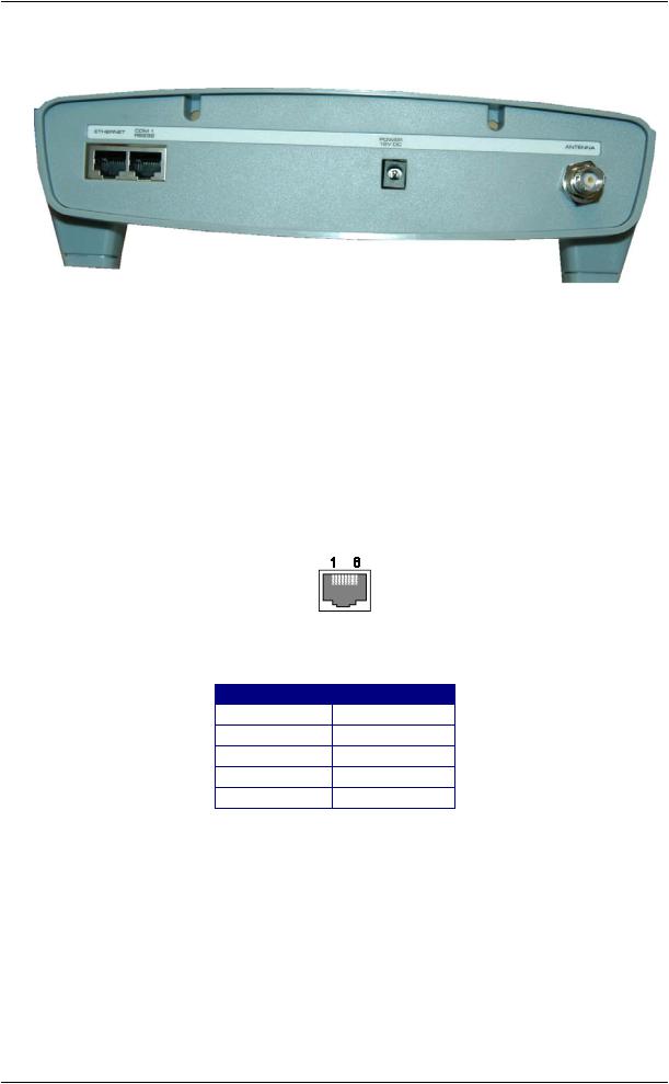
1.3Rear Panel
1.3.1Connectors
•Ethernet
The RJ45 Ethernet port may be used for connection to a PC or external system for configuration or operational purposes.
•RS232
The RS232 port may be used for connection to a PC or external system for configuration or operational purposes. Details of the required RS232 pins are as follows:
The pinouts are described below.
Abbreviation |
Pin Number |
GND |
4 |
RX |
5 |
TX |
6 |
CTS |
7 |
RTS |
8 |
Antenna Port
The antenna port is an opening to allow connection of the antenna to the internal transmitter. The connector is a standard BNC 50ohm.
1.3.2DC Input
This connector is used to supply power to the unit. The CMM requires 12VDC @ 2amps regulated. You will have been supplied with a suitable power supply with mains lead which will plug straight into this socket.
Page 10 |
© CommtechWireless |
Manual |
Fusion Intelpage IP |
2 |
INTELPAGE IP 5 INSTALLATION |
2.1Enclosure Mounting
Before mounting the enclosure, you will need to decide where to place the unit. The Intelpage IP comes default with rubber feet installed, allowing it to sit on a desk or table, or be stacked upon other plastic Fusion Series modules.
The kit also includes a wall mounting bracket. To install this bracket:
1.Use a philips screwdriver to remove the four screws holding the rubber feet
2.Seat the bracket on the base of the unit. It will only fit one way around.
3.Use the screws that used to hold the rubber feet in position, to hold the wall mount bracket in position.
2.2Antenna
A suitable antenna capable of handling 5 watts must be connected to the BNC connector on the rear panel. The antenna for the unit must not be mounted within 5 metres of any other sensitive electronic equipment including other Fusion series products, routers, computers or phone systems. See the technical information section below for further infomation.
▲ WARNING: The antenna must be placed at least 5 metres away from other electonic equipment to prevent interference.
© CommtechWireless |
Page 11 |

Fusion Intelpage IP |
Manual |
3 SOFTWARE CONFIGURATION
To configure Intelpage IP 5, you will need a PC with either:
1. A terminal program with a straight-through serial cable
The terminal interface has one extra field compared to the HTML interface below which is the MAC address for the unit. The MAC address is a unique networking address assigned to each unit. This is factory set and will not normally require alteration. For this reason it is recommended that the www/HTML interface described below be used.
2. An Ethernet connection to the unit through an RJ45 cable (www/HTML)
This is the recommended method for setting up you Intelpage IP 5.
Skip to the required section below for more information on these two methods.
3.1Configuring through a Terminal Program
NOTE: HyperTerminal is used as the terminal emulator in this example. If it is not installed, it can be added by changing your Windows settings. Other terminal programs may be used.
1.Using a straight-through serial cable, connect the Intelpage IP 5 unit to the serial port of a PC. A straight-through serial cable must be used – a null modem cable will not work. See the Technical Information section for information regarding making up or obtaining a suitable serial lead.
2.Make sure that the power is not currently plugged into the Intelpage IP 5 unit at this stage.
3.Start HyperTerminal. It can generally be found from the Windows start menu by selecting Start -> Programs -> Accessories -> Communications -> HyperTerminal
4.At the Connection Description window, add a name for the entry (such as Intelpage IP 5) and click [OK].
Page 12 |
© CommtechWireless |
Manual |
Fusion Intelpage IP |
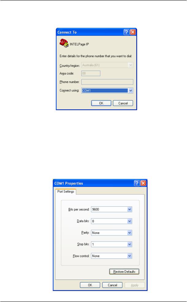
5.At the Connect To window, go to Connect Using and scroll to your serial port (normally COM1 or COM2). Usually, this information is written next to the serial port on the back of the computer. Then click [OK].
6.At the COM port properties window, click the [Restore Defaults] button. This will automatically update the screen with the correct settings below.
•Bits per second should match that of Intelpage IP 5 (default is 9600).
•Data bits should be 8
•Parity should be None
•Stop bits should be 1
•Flow control should be None
When the correct settings have been entered, click [OK] to proceed.
© CommtechWireless |
Page 13 |
Fusion Intelpage IP |
Manual |
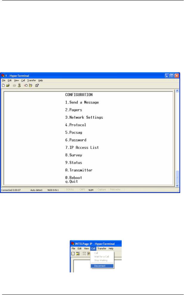
7.You should then see a HyperTerminal window as shown below. If no errors were encountered, HyperTerminal will display Connected in the bottom left corner (status bar).
8.At this point, connect the power to the Intelpage IP 5 unit. Within the next five seconds, press the [Escape] key four times to bring up a password request screen. By default, the password is “public” (without the quotations). If the password request does not come up, check your serial cable and your connection settings.
9.From the Main Menu, a selection is made by pressing the number corresponding to the settings you want to edit (e.g. to select Network you would press [3]). Once selected, the fields within can be navigated by pressing the [TAB] or [Enter] key. To change the values of fields that only allow toggling, use the [SPACE] bar. Generally, pressing [s] will save and bring you back to the Main Menu, whilst [x] will not save any changes.
10.The menu structure and fields are much the same as in the HTML (web) interface and will be described in more detail below.
11.Once you have finished making settings changes in HyperTerminal, go to the main menu and select Reboot (if need be) or Quit. Then go to the Call menu in the HyperTerminal window and select Disconnect.
Page 14 |
© CommtechWireless |

Manual |
Fusion Intelpage IP |
3.1.1User Interface Fields
Manual Paging
From the Main Menu, select [1] to enter the manual paging screen. This screen is used to send out manual pages to either entries in the pager database or to a specific cap code.
Pager Database Editing
From the Main Menu, select [2] to enter the pager database edit screen. This screen is used to edit Intelpage IP 5’s internal pager database. By selecting a pager ID, you can edit the cap code and pager type. (alpha, numeric , tone)
© CommtechWireless |
Page 15 |
Fusion Intelpage IP |
Manual |
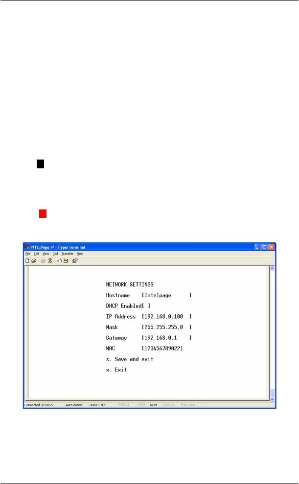
Network Settings
From the Main Menu, select [3] to enter the network settings screen.
•Hostname - The hostname is a unique name that identifies a device on the network.
•DHCP Enabled – Dynamic Host Configuration Protocol. If this service exists on your network it can provide the device an IP address, mask and gateway automatically. Some DHCP servers allow the reservation of an IP address for a specified MAC address. If DHCP is not used (box unchecked), the IP address, mask and gateway have to be manually configured. Please consult your IT administrator for these settings. (default Off)
•IP Address - The IP Address of the Intelpage IP 5 unit. (default 192.168.0.100)
•Mask - The network mask of the network you are connected to. (default 255.255.255.0)
•Gateway - If the device is to be accessed from the internet or another network, the gateway is the route used to reach the external network. (default 192.168.0.1)
NOTE: The IP address, mask and gateway fields will display the current settings.
If DHCP is enabled, any changes to the fields will not be saved as they are server assigned.
•MAC - This is the Intelpage IP 5’s unique hardware number on the network. The Media Access Control address is factory set and should not need to be changed.
▲WARNING: Care should be taken if altering the MAC address, as it can result in the unit no longer being addressable.
Page 16 |
© CommtechWireless |
 Loading...