


F300S/F300SQ Ultraviolet Lamp System
Installation, Operation, and Maintenance
Manual No. 509252 Rev R 3/04
FUSION UV SYSTEMS, INC.
910 Clopper Road
Gaithersburg, MD 20878-1357 USA
(301) 527-2660 • FAX (301) 527-2661

F300S/F300SQ Ultraviolet
Lamp System
Installation, Operation, and Maintenance
Manual No. 509252 Rev R 3/04
Applies to systems using P300M/P300MQ/P300MT power supplies,
and I300M/I310M series irradiators Serial Numbers 1001 and later.
(C) Copyright 2004 Fusion UV Systems, Inc. All Rights Reserved.
The products covered herein conform to EC standards.
See Appendix A for details.
FUSION UV SYSTEMS, INC.
910 Clopper Road
Gaithersburg, MD 20878-1357 USA
(301) 527-2660 • FAX (301) 527-2661


Table Of Contents
Introduction . . . . . . . . . . . . . . . . . . . . . . . . . . . . . . . . . . . . . . . . . . . . . . . . . 11
Document Conventions . . . . . . . . . . . . . . . . . . . . . . . . . . . . . . . . 12
Indications of Note, Caution, Warning, and Danger . . . . . . . . . 12
Icon Usage . . . . . . . . . . . . . . . . . . . . . . . . . . . . . . . . . . . . . 13
System Description . . . . . . . . . . . . . . . . . . . . . . . . . . . . . . . . . . 15
System Components . . . . . . . . . . . . . . . . . . . . . . . . . . . . . . . . . 17
Control . . . . . . . . . . . . . . . . . . . . . . . . . . . . . . . . . . . . . . . . 17
Cooling . . . . . . . . . . . . . . . . . . . . . . . . . . . . . . . . . . . . . . . 18
Irradiators . . . . . . . . . . . . . . . . . . . . . . . . . . . . . . . . . . . . . . . . . 18
Reflector and Cavity . . . . . . . . . . . . . . . . . . . . . . . . . . . . . . 19
Lamp Bulb . . . . . . . . . . . . . . . . . . . . . . . . . . . . . . . . . . . . . 19
Mounting . . . . . . . . . . . . . . . . . . . . . . . . . . . . . . . . . . . . . . 20
Power Supply . . . . . . . . . . . . . . . . . . . . . . . . . . . . . . . . . . . . . . 20
P300M/P300MQ/P300MT . . . . . . . . . . . . . . . . . . . . . . . . . . . 20
RF Detector . . . . . . . . . . . . . . . . . . . . . . . . . . . . . . . . . . . . . . . . 20
System Interconnections . . . . . . . . . . . . . . . . . . . . . . . . . . . . . . 20
Warranty Policy . . . . . . . . . . . . . . . . . . . . . . . . . . . . . . . . . . . . . 21
Shipping Instructions . . . . . . . . . . . . . . . . . . . . . . . . . . . . . . . . . 22
Returned Material Authorization Number . . . . . . . . . . . . . . . . 22
General Packing Instructions . . . . . . . . . . . . . . . . . . . . . . . . 22
Power Supply . . . . . . . . . . . . . . . . . . . . . . . . . . . . . . . . 22
Irradiators . . . . . . . . . . . . . . . . . . . . . . . . . . . . . . . . . . . . . 23
Magnetrons . . . . . . . . . . . . . . . . . . . . . . . . . . . . . . . . . . . . 23
UV Bulbs . . . . . . . . . . . . . . . . . . . . . . . . . . . . . . . . . . . . . . 23
Control Cards . . . . . . . . . . . . . . . . . . . . . . . . . . . . . . . . . . . 23
RF Detectors . . . . . . . . . . . . . . . . . . . . . . . . . . . . . . . . . . . . 23
Chapter 1. Safety . . . . . . . . . . . . . . . . . . . . . . . . . . . . . . . . . . . . . . . . . . . . 25
Ultraviolet Radiation . . . . . . . . . . . . . . . . . . . . . . . . . . . . . . . . . . 26
Microwave Radiation . . . . . . . . . . . . . . . . . . . . . . . . . . . . . . . . . . 26
Personnel Effects of Microwave Radiation . . . . . . . . . . . . . . . . . . . 27
Radio Interference . . . . . . . . . . . . . . . . . . . . . . . . . . . . . . . . . . . 27
Ozone . . . . . . . . . . . . . . . . . . . . . . . . . . . . . . . . . . . . . . . . . . . . 28
Installation, Operation, and Maintenance Manual # 509252 Rev R 5

Temperature . . . . . . . . . . . . . . . . . . . . . . . . . . . . . . . . . . . . . . . 28
High Voltage . . . . . . . . . . . . . . . . . . . . . . . . . . . . . . . . . . . . . . . 29
UV Curable Materials . . . . . . . . . . . . . . . . . . . . . . . . . . . . . . . . . 29
Chapter 2. Mechanical Installation . . . . . . . . . . . . . . . . . . . . . . . . . . . . . . 31
Mechanical Installation Checklist . . . . . . . . . . . . . . . . . . . . . . . . . 31
Unpacking and Inspection . . . . . . . . . . . . . . . . . . . . . . . . . . 31
Power Supply Unit(s) Placement . . . . . . . . . . . . . . . . . . . . . . . . . 32
Irradiator Mounting . . . . . . . . . . . . . . . . . . . . . . . . . . . . . . . . . . 33
Lamps Mounted in Opposing Configuration . . . . . . . . . . . . . . . . . . 34
UV Light Shielding . . . . . . . . . . . . . . . . . . . . . . . . . . . . . . . . . . . 34
RF Detector Mounting . . . . . . . . . . . . . . . . . . . . . . . . . . . . . . . . . 35
Remote Blowers . . . . . . . . . . . . . . . . . . . . . . . . . . . . . . . . . . . . . 36
Irradiator Exhaust Venting . . . . . . . . . . . . . . . . . . . . . . . . . . . . . 36
Quartz Plates . . . . . . . . . . . . . . . . . . . . . . . . . . . . . . . . . . . . . . . 36
Chapter 3. Electrical System . . . . . . . . . . . . . . . . . . . . . . . . . . . . . . . . . . . 39
Electrical Installation/Setup Checklist . . . . . . . . . . . . . . . . . . . . . . 39
Accessory Parts List . . . . . . . . . . . . . . . . . . . . . . . . . . . . . . . . . . 39
Interconnect Cables . . . . . . . . . . . . . . . . . . . . . . . . . . . . . . . . . . 40
Connection and Program Log . . . . . . . . . . . . . . . . . . . . . . . . . . . . 40
Installing the External Interlocks Control . . . . . . . . . . . . . . . . 40
User Connections . . . . . . . . . . . . . . . . . . . . . . . . . . . . . . . . 40
Power Supply Programming . . . . . . . . . . . . . . . . . . . . . . . . . . . . . 41
Settings for Six-Position Switch S1 . . . . . . . . . . . . . . . . . . . . 41
Single Unit Programming and Connections . . . . . . . . . . . . . . . . . . 43
Programming . . . . . . . . . . . . . . . . . . . . . . . . . . . . . . . . . . . . . . . 44
Irradiator Cable H340 Connections . . . . . . . . . . . . . . . . . . . . 44
Input/Output Connections . . . . . . . . . . . . . . . . . . . . . . . . . . 45
Remote Inputs . . . . . . . . . . . . . . . . . . . . . . . . . . . . . . . . . . 45
Output Ports (J105B) . . . . . . . . . . . . . . . . . . . . . . . . . . . . . . . . . 46
Alternate Function for K5 . . . . . . . . . . . . . . . . . . . . . . . . . . . 47
Multiple-Unit Programming and Connections . . . . . . . . . . . . . . . . . 48
Programming . . . . . . . . . . . . . . . . . . . . . . . . . . . . . . . . . . . 49
Connections . . . . . . . . . . . . . . . . . . . . . . . . . . . . . . . . . . . . 49
6 F300S/F300SQ Ultraviolet Lamp System

Power Source . . . . . . . . . . . . . . . . . . . . . . . . . . . . . . . . . . . . . . 50
System Power Connections . . . . . . . . . . . . . . . . . . . . . . . . . . 50
Frequency Tapping of HV Capacitors . . . . . . . . . . . . . . . . . . . 51
QRO HV Capacitors (For QRO only) . . . . . . . . . . . . . . . . . . . . 51
High Voltage Transformer Taps . . . . . . . . . . . . . . . . . . . . . . . 51
QRO Transformer Taps (FOR QRO only) . . . . . . . . . . . . . . . . . 52
F300S Relay Coil Resistor Assembly Installation . . . . . . . . . . . . . . 53
Installation Instructions . . . . . . . . . . . . . . . . . . . . . . . . . . . . 53
Chapter 4. Operation . . . . . . . . . . . . . . . . . . . . . . . . . . . . . . . . . . . . . . . . . 55
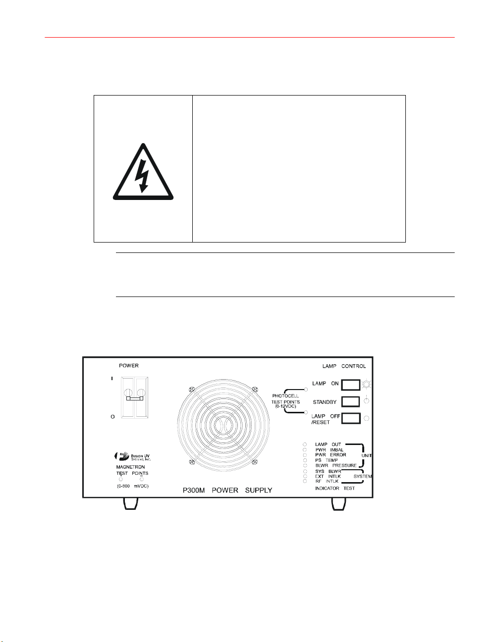
System Operation Controls . . . . . . . . . . . . . . . . . . . . . . . . . . . . . 55
Lamp Control . . . . . . . . . . . . . . . . . . . . . . . . . . . . . . . . . . . 55
Power . . . . . . . . . . . . . . . . . . . . . . . . . . . . . . . . . . . . . . . . 56
Off/Reset Control . . . . . . . . . . . . . . . . . . . . . . . . . . . . . . . . 56
Initial Startup Procedure, Single Unit . . . . . . . . . . . . . . . . . . . . . . 56
Initial Startup Procedure, Multiple-Unit Systems . . . . . . . . . . . . . . 57
Master/Slave Operation . . . . . . . . . . . . . . . . . . . . . . . . . . . . 57
Operating the System . . . . . . . . . . . . . . . . . . . . . . . . . . . . . 57
Resetting the System After a Fault . . . . . . . . . . . . . . . . . . . . 58
Remote Operation . . . . . . . . . . . . . . . . . . . . . . . . . . . . . . . . . . . 59
Operation with Remote Controls . . . . . . . . . . . . . . . . . . . . . . 60
Quick Restart Option (QRO) . . . . . . . . . . . . . . . . . . . . . . . . . . . . 60
Electrical Installation and Setup . . . . . . . . . . . . . . . . . . . . . . 63
Operation . . . . . . . . . . . . . . . . . . . . . . . . . . . . . . . . . . . . . . 63
Chapter 5. Troubleshooting . . . . . . . . . . . . . . . . . . . . . . . . . . . . . . . . . . . 65
Basic Checks . . . . . . . . . . . . . . . . . . . . . . . . . . . . . . . . . . . . . . . 65
Safety Interlock Tests . . . . . . . . . . . . . . . . . . . . . . . . . . . . . . . . . 66
Fault Indicators . . . . . . . . . . . . . . . . . . . . . . . . . . . . . . . . . . . . . 66
Unit Faults . . . . . . . . . . . . . . . . . . . . . . . . . . . . . . . . . . . . . 66
System Faults . . . . . . . . . . . . . . . . . . . . . . . . . . . . . . . . . . . 67
Fault Diagnosis Tables . . . . . . . . . . . . . . . . . . . . . . . . . . . . . . . . 67
Failure Diagnosis Cross-Reference . . . . . . . . . . . . . . . . . . . . . . . . 68
Chapter 6. Maintenance . . . . . . . . . . . . . . . . . . . . . . . . . . . . . . . . . . . . . . . 79
I300M Irradiator . . . . . . . . . . . . . . . . . . . . . . . . . . . . . . . . . . . . 79
Installation, Operation, and Maintenance Manual # 509252 Rev R 7

Bulb, Screen, and Reflector Maintenance . . . . . . . . . . . . . . . . 79
Cleaning Guidelines . . . . . . . . . . . . . . . . . . . . . . . . . . . 79
Bulb Cleaning . . . . . . . . . . . . . . . . . . . . . . . . . . . . . . . . 79
Reflector Cleaning . . . . . . . . . . . . . . . . . . . . . . . . . . . . . 79
Screen Cleaning . . . . . . . . . . . . . . . . . . . . . . . . . . . . . . 80
I300M Screen Assembly Removal/Replacement . . . . . . . . . . . 80
Lamp Bulb Removal/Replacement . . . . . . . . . . . . . . . . . . . . 81
Reflector Removal/Replacement . . . . . . . . . . . . . . . . . . . . . . 82
I300M Irradiator Housing Removal/Replacement . . . . . . . . . . 86
Direct View Photoresistor Removal/Replacement . . . . . . . . . . . 87
Filament Transformer Removal/Replacement . . . . . . . . . . . . . 88
Magnetron Removal/Replacement . . . . . . . . . . . . . . . . . . . . . 89
Air Pressure Verification . . . . . . . . . . . . . . . . . . . . . . . . . . . . 90
Air Pressure Switch Replacement . . . . . . . . . . . . . . . . . . 91
I310M/I311M Irradiator . . . . . . . . . . . . . . . . . . . . . . . . . . . . . . . 91
Bulb, Screen, and Reflector Maintenance . . . . . . . . . . . . . . . . 91
Cleaning Guidelines . . . . . . . . . . . . . . . . . . . . . . . . . . . 91
Bulb Cleaning . . . . . . . . . . . . . . . . . . . . . . . . . . . . . . . . 92
Reflector Cleaning . . . . . . . . . . . . . . . . . . . . . . . . . . . . . 92
Screen Cleaning . . . . . . . . . . . . . . . . . . . . . . . . . . . . . . 92
Screen Assembly Removal/Replacement . . . . . . . . . . . . . . . . 93
Lamp Bulb Removal/Replacement . . . . . . . . . . . . . . . . . . . . 93
Reflector Removal/Replacement . . . . . . . . . . . . . . . . . . . . . . 94
Replacing the RF Gasket Assembly . . . . . . . . . . . . . . . . . 99
I310M/I311M Irradiator Housing Removal/Replacement . . . . . 100
I310M/I311M Scatter View Photoresistor Removal/Replacement . .
100
Direct View Photoresistor Removal/Replacement . . . . . . . . . . 101
Filament Transformer Removal/Replacement . . . . . . . . . . . . 103
Magnetron Removal/Replacement . . . . . . . . . . . . . . . . . . . . 104
Air Pressure Verification . . . . . . . . . . . . . . . . . . . . . . . . . . . 105
Air Pressure Switch Replacement . . . . . . . . . . . . . . . . . 105
P300M/P300MQ Power Supply . . . . . . . . . . . . . . . . . . . . . . . . . . 106
Safety Procedures . . . . . . . . . . . . . . . . . . . . . . . . . . . . . . . 106
Test Point Voltages . . . . . . . . . . . . . . . . . . . . . . . . . . . . . . 107
8 F300S/F300SQ Ultraviolet Lamp System

Control Card Removal/Replacement . . . . . . . . . . . . . . . 107
Diode Test . . . . . . . . . . . . . . . . . . . . . . . . . . . . . . . . . 108
Capacitor Test . . . . . . . . . . . . . . . . . . . . . . . . . . . . . . 110
High Voltage Transformer Removal/Replacement . . . . . . 110
P300MT Power Supply . . . . . . . . . . . . . . . . . . . . . . . . . . . . . . . 112
Routine Maintenance . . . . . . . . . . . . . . . . . . . . . . . . . . . . . 112
Safety Procedures . . . . . . . . . . . . . . . . . . . . . . . . . . . . 112
Test Point Voltages. . . . . . . . . . . . . . . . . . . . . . . . . . . . . . . 113
Control Card Removal/Replacement . . . . . . . . . . . . . . . . . . . 113
Diode Test . . . . . . . . . . . . . . . . . . . . . . . . . . . . . . . . . . . . 114
Capacitor Test . . . . . . . . . . . . . . . . . . . . . . . . . . . . . . . . . . 115
High Voltage Transformer Removal/Replacement . . . . . . 116
K300 Modular Blower . . . . . . . . . . . . . . . . . . . . . . . . . . . . . . . . 117
Routine Maintenance . . . . . . . . . . . . . . . . . . . . . . . . . . . . . 117
Blower Air Filters . . . . . . . . . . . . . . . . . . . . . . . . . . . . 117
Blower Cover Removal . . . . . . . . . . . . . . . . . . . . . . . . 118
Motor Replacement . . . . . . . . . . . . . . . . . . . . . . . . . . . 118
Appendix A. Specifications . . . . . . . . . . . . . . . . . . . . . . . . . . . . . . . . . . . 121
System . . . . . . . . . . . . . . . . . . . . . . . . . . . . . . . . . . . . . . . . . 121
Power Supply . . . . . . . . . . . . . . . . . . . . . . . . . . . . . . . . . . . . . 121
Irradiators . . . . . . . . . . . . . . . . . . . . . . . . . . . . . . . . . . . . . . . . 123
Blower . . . . . . . . . . . . . . . . . . . . . . . . . . . . . . . . . . . . . . . 124
RF Detector . . . . . . . . . . . . . . . . . . . . . . . . . . . . . . . . . . . 124
System Agency Approvals . . . . . . . . . . . . . . . . . . . . . . . . . 125
Appendix B. Cables and Connectors . . . . . . . . . . . . . . . . . . . . . . . . . . . 127
Interconnect Cables . . . . . . . . . . . . . . . . . . . . . . . . . . . . . . . . . 127
System Connector Contact Kits . . . . . . . . . . . . . . . . . . . . . . 128
Appendix C. Outline Drawings . . . . . . . . . . . . . . . . . . . . . . . . . . . . . . . . 129
Appendix D. Lamp System Maintenance Log . . . . . . . . . . . . . . . . . . . . 139
Appendix E. Replacement Parts . . . . . . . . . . . . . . . . . . . . . . . . . . . . . . . 141
I300M/I310M Irradiator Parts List . . . . . . . . . . . . . . . . . . . . . . . 142
Installation, Operation, and Maintenance Manual # 509252 Rev R 9

P300M/P300MT Power Supply Parts List . . . . . . . . . . . . . . . . . . . 144
P300MQ Quick Restart Option Parts List . . . . . . . . . . . . . . . . . . . 146
K300 Blower Assembly Parts List . . . . . . . . . . . . . . . . . . . . . . . 147
Appendix F. Ignitor Bulb . . . . . . . . . . . . . . . . . . . . . . . . . . . . . . . . . . . . . 149
Ignitor . . . . . . . . . . . . . . . . . . . . . . . . . . . . . . . . . . . . . . . . . . 149
Ignitor Bulb Removal/Replacement . . . . . . . . . . . . . . . . . . . . . . 150
Appendix G. Schematics . . . . . . . . . . . . . . . . . . . . . . . . . . . . . . . . . . . . . 153
10 F300S/F300SQ Ultraviolet Lamp System

Introduction
This manual is designed to be used, not set aside until problems occur. The following
list of chapters and appendixes describes where to find information in this manual.
• This Introduction provides a brief description of the total system, and system
components. It also contains the Fusion UV Systems warranty policy and shipping
instructions for returning equipment.
• Chapter 1, “Safety,” contains important information! This chapter should be read
by all persons who will operate or troubleshoot system equipment.
• Chapter 2, “Mechanical Installation,” gives unpacking instructions, and
instructions for equipment placement, mounting, shielding and exhaust venting.
• Chapter 3, “Electrical System,” explains the power supply software setup,
including single and multiple unit programming and connections. HV capacitor
frequency tapping instructions are also provided.
• Chapter 4, “Operation,” describes steps for initial startup for both single and
multiple unit systems, how to operate master/slave and remote systems, and how
to reset the system after a fault. It also contains setup and operations instructions
for the Quick Restart Option (QRO).
• Chapter 5, “Troubleshooting,” consists mainly of information in table form. There
is a reference table for faults and indications, tables describing unit and system
fault indications, and a fault diagnosis table. The fault diagnosis table provides
faults, causes, and corrective actions.
• Chapter 6, “Maintenance,” covers routine maintenance and removal/replacement
instructions for the irradiator, power supply and modular blower. There is a
maintenance procedure page locator at the front of the chapter.
• Appendix A, “Specifications,” outlines the various characteristics of major
components of the F300S/F300SQ Ultraviolet Lamp System. It also lists agency
approvals and certificates for the relevant systems and components.
• Appendix B, “Cables and Connectors,” provides information on the interconnect
cables and system connector contact kits used with the F300S/F300SQ Ultraviolet
Lamp System.
Installation, Operation, and Maintenance Manual # 509252 Rev R 11

• Appendix C, “Outline Drawings,” contains drawings that provide overview details
for general reference for Fusion UV Systems products. These drawings are not to
be used in designing an installation; contact Fusion directly for current
specifications.
• Appendix D, “Lamp System Maintenance Log,” contains an example of a Fusion
UV Systems form to use for tracking lamp system maintenance.
• Appendix E, “Replacement Parts,” lists the various accessory replacement parts
available for Fusion UV Systems Irradiators.
• Appendix F, “Ignitor Bulb,” applies to lamps manufactured before July 1, 2002. It
describes the operation of the ignitor bulb that provides ignition to the main bulb.
• Appendix G, “Schematics,” contains figures that illustrate the various wiring
diagrams for Irradiator components.
Document Conventions
The products and components discussed in this document are designed and tested for
safe operation; however, they use technologies and resources that have inherent risks.
This section describes the conventions used throughout this manual when discussing
such technologies, so that users can plan and act accordingly when installing,
operating, or troubleshooting equipment.
Indications of Note, Caution, Warning, and Danger
Four categories of notice are indicated in this document; descriptions and examples of
their formatting are provided next.
NOTE: Notes serve to point out additional information about a subject or
process that is important, but not hazard-related.
CAUTION: Cautions generally indicate areas where a user should take
special care to avoid minor or moderate injury. It may also indicate
unsafe practices that could damage equipment or materials.
WARNING: Warnings indicate actions that can cause recoverable physical
harm; or destruction of equipment, data, or products.
12 F300S/F300SQ Ultraviolet Lamp System
Icon Usage
Several icons are used throughout the documentation to identify the types of hazardous
resources or technologies used when working with a particular aspect of the system.
Table 1, “Icons,” lists these and their definitions. Exercise extreme care by reading the
material thoroughly and following all procedures when working with the various
components.
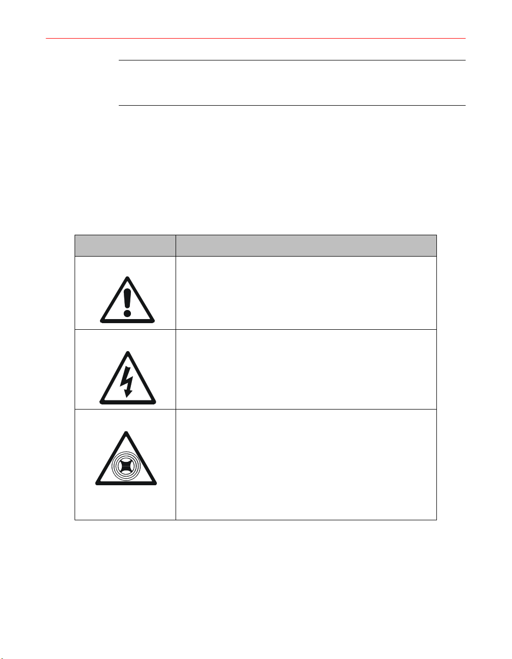
Icon Definition
DANGER: Danger indications identify conditions where death or
permanent injury to personnel can occur if proper procedures and
precautions are not followed.
Table 1. Icons
CAUTION:
Exclamation Mark: This icon is used for other instances and
items for which a standard symbol does not exist.
CAUTION: Risk of Electric Shock
This icon identifies instances where dangerous or lethal
voltages might be present when working with various
components of the irradiator or site power.
CAUTION: Microwave Radiation
The Fusion UV Lamp System is powered by high
energy RF microwave power which can be dangerous if
misused or inadequately shielded. The lamp system
should never be turned on if the lamp housing and
screen are not intact, or if the microwave leak detector
and interlock are not functioning.
Installation, Operation, and Maintenance Manual # 509252 Rev R 13
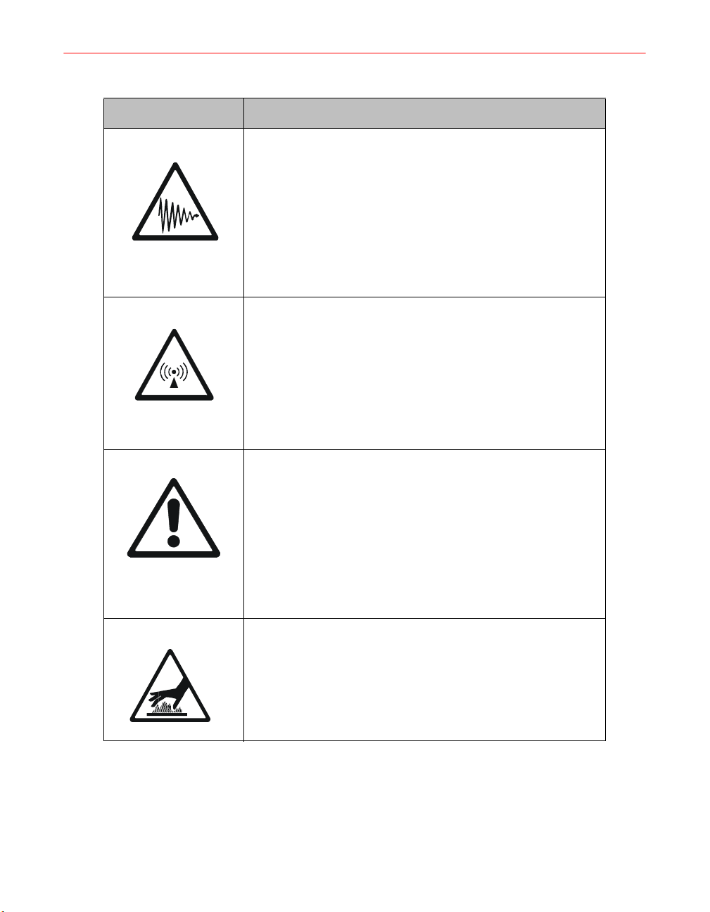
Table 1. Icons (continued)
Icon Definition
CAUTION: Ultraviolet Radiation
This icon identifies instances where damaging levels of
ultraviolet radiation may be present. Adequate shielding
around the equipment and region must be provided, and
personnel should
certified lenses.
should wear gloves and long sleeves to protect their hands
and arms, and ensure that their legs are covered.
CAUTION: Radio Interference
be required to wear goggles with UV
All personnel within ten feet of the lamp
Fusion lamps operate at a fundamental frequency of
2.45 GHz. The unit may cause interference with some
local area networks (LANs) that also operate at this
frequency. Please check with your LAN manufacturer
for compatibility. Ensure that the equipment is properly
maintained and shielded.
CAUTION: Ozone
High concentrations of ozone can cause discomfort, or at
sufficiently high levels be dangerous. Although Fusion lamp
systems make ozone at a level that could barely be detected
by odor and at a factor of five below the level of 0.1 parts per
million allowable for continuous exposure (American
Conference of Governmental Hygienists), all Fusion UV Lamp
Systems should be exhausted to the outdoors.
CAUTION: Hot Temperature, Do Not Touch
Surface temperatures of the lamp during normal
operation may exceed 120
the lamp will also be hot. Observe appropriate
precautions to avoid burns.
14 F300S/F300SQ Ultraviolet Lamp System
o
F. Metal components near
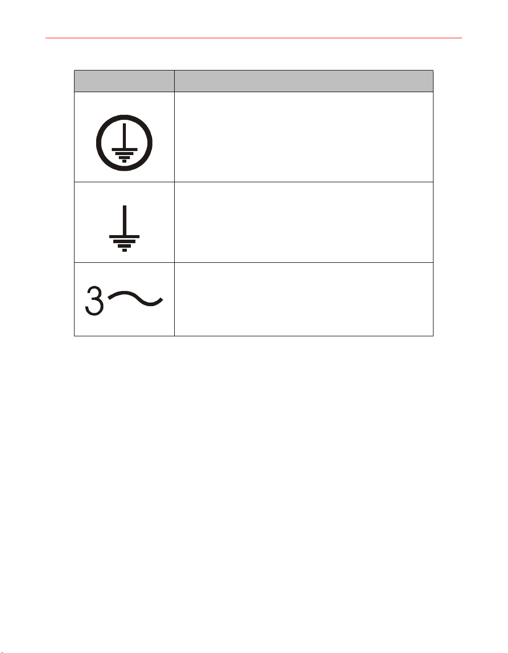
Table 1. Icons (continued)
Icon Definition
Protective Conductor Terminal
Earth (ground) Terminal
Three Phase Alternating Current
System Description
The Fusion Ultraviolet Lamp System has been designed specifically for applications
involving the industrial curing of inks and coatings and may be used effectively for a
wide variety of applications.
An ultraviolet (UV) lamp system for industrial curing must generate extremely intense
radiation in the 200-400 nanometer region. Such radiation, when properly generated
and focused, and used in conjunction with specially formulated UV sensitive inks and
coatings, causes virtually instantaneous curing (drying) of the exposed materials.
The unique properties of the Fusion UV Lamp System are obtained by using
microwave radiation to energize the lamp. Microwave energy at 2450 MHZ is
generated by a power tube (magnetron) of the type widely available for commercial
microwave cooking ovens. The patented Fusion UV Systems lamp has no electrodes,
and consequently overcomes many of the basic limitations of conventional mercury
arc lamps.
Installation, Operation, and Maintenance Manual # 509252 Rev R 15

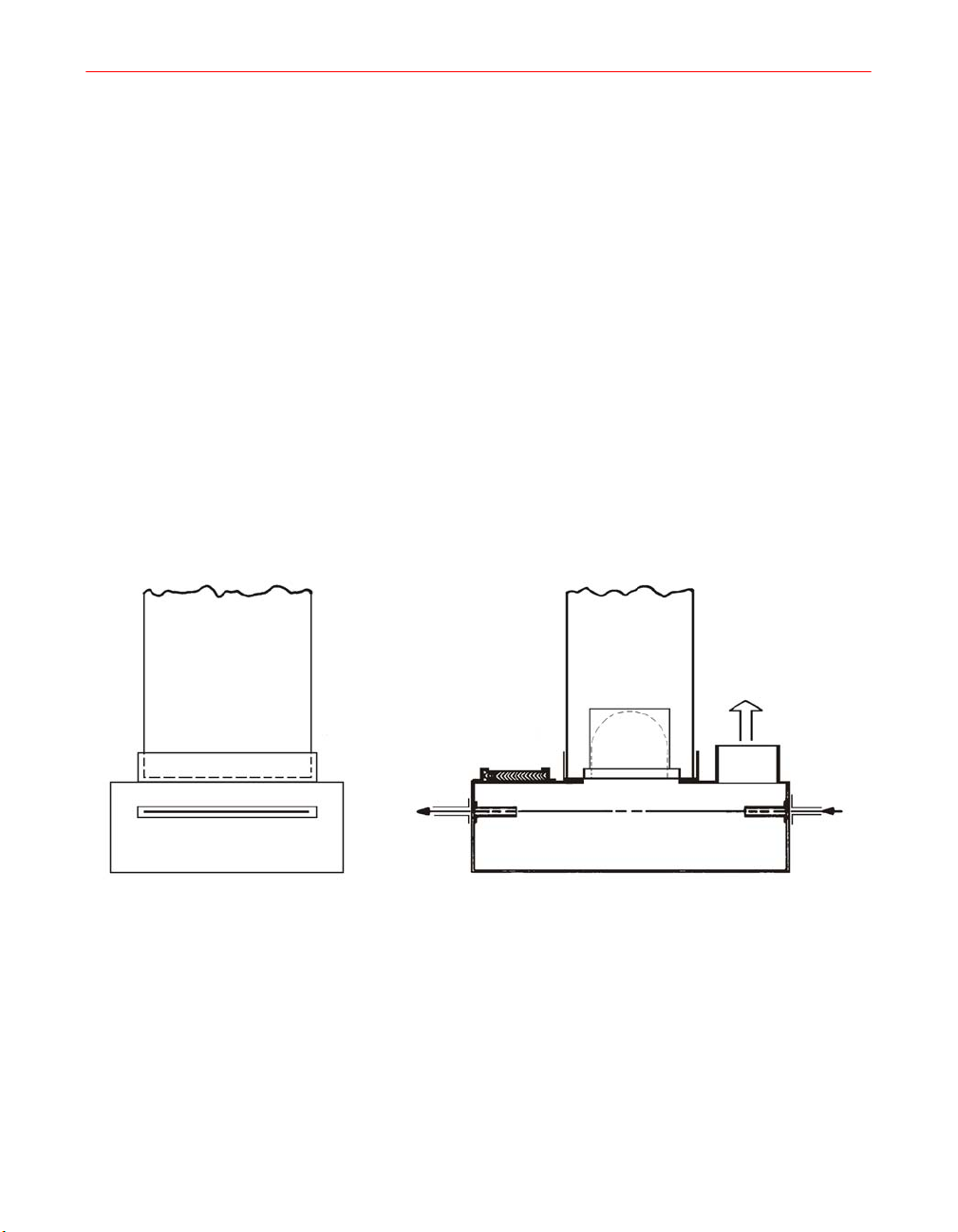
Figure 1. F300S/F300SQ Lamp System
The F300S/F300SQ Fusion UV Lamp System (Figure 1) is modular, consisting of
independent 6-inch (15.2 cm) lamp units and corresponding modular power supplies.
Two lamps can be placed end-to-end to form a 12-inch (30.5 cm) lamp system or can
be placed in a continuous array to form lamps of 18-inch (45.7 cm), etc. This is
possible because the illumination of the lamp is a full 6". When two 6" lamps are
placed end-to-end forming a 12" lamp, material being irradiated in the focal plane
53.3mm (2.1") below the lamp bottom, and at the juncture between the two lamps,
receives sufficient radiation from each 6" module to provide uniform curing over the
entire region.
Microwave energy from a single magnetron is directed into the cavity formed by an
aluminum reflector and a screen over the bottom of the reflector. The lamp bulb is
located inside this chamber. The screen keeps microwaves inside the chamber but
allows UV light to pass through onto the material to be cured.
16 F300S/F300SQ Ultraviolet Lamp System

Electrical inputs to the lamp module are provided by a high voltage/control cable with
a quick-connect fitting which supplies power for the magnetron, filament transformer
and the interlock circuitry.
System Components
The basic F300S/F300SQ system consists of the following items:
• A P300M/P300MQ/P300MT power supply
• An HV Cable H340 (no modular blower)
• An HV Cable H341 (with modular blower)
• An I300 series irradiator
• An RF detector cable H790
• An RF-1 detector
In addition, the user must supply the following if not provided by Fusion UV Systems:
• Cooling for the irradiator, if no modular blower is provided. (See Appendix A,
“Specifications” and Appendix C, “Outline Drawings” for irradiator cooling
requirements.)
• Mechanical mounting of the lamp modules over a substrate, conveyor, or other
transport mechanism
Control
• Light shield surrounding the lamps
• Exhaust system for the light shield
• Any desired interlock mechanisms (see Chapter 3 on page 39)
• Electrical wiring of the power supply into the plant electrical system
The control system of the F300S/F300SQ provides precise control of high voltage and
filament voltage supplies. The control board also monitors cooling air pressure,
detection of RF, power levels, bulb ignition, and interlocks such as transformer
thermal switches. If a problem arises, the control system turns off all high voltage
power to the lamp and flashes a fault LED indicator on the power supply control panel.
Inputs for customer ON/OFF control are available. Outputs allow detection of
STANDBY or LAMP ON operation, or of interlock failures.
Installation, Operation, and Maintenance Manual # 509252 Rev R 17
Cooling
Irradiators
Proper operation of the lamp requires adequate cooling of the magnetron and the bulb.
(See Appendix C, page 129, for irradiator cooling requirements.) Cooling air from a
blower goes through the magnetron cooling fins and into the lamp housing. At this
point, the airflow splits into two paths: one path exhausts through the irradiator
housing vent holes, and the rest of the air flows into the cavity through cooling holes
in the reflector. This airflow cools the bulb and exhausts through the RF screen.
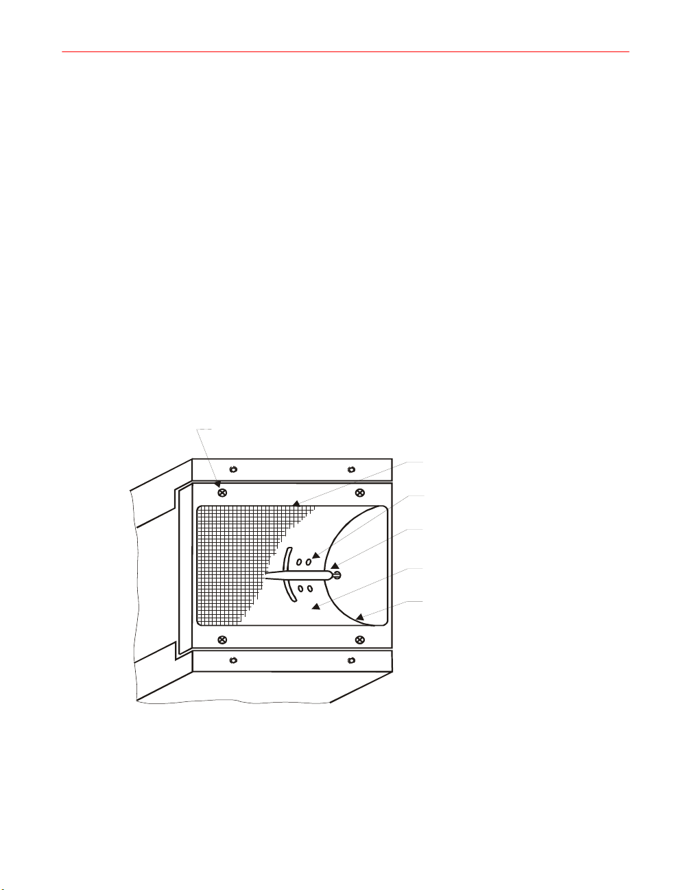
The I300M irradiator family is the heart of the UV system. For example, the model
I300M contains both the 15.2 cm (6") long electrodeless lamp bulb mounted in the
elliptical reflector and the magnetron which energizes the bulb. The reflector is
elliptical in cross-section and the lamp bulb is mounted at the focus of the ellipse,
producing an intense strip of light at the other focus of the reflector (53 mm [2.1"]
below the bottom rails of the lamp).
M3 screen retaining
screws (4) (2 per side)
RF screen
18 F300S/F300SQ Ultraviolet Lamp System
Cooling air holes
Lamp bulb
Cavity
Reflector
Figure 2. Reflector Assembly
The following table lists the various irradiator models manufactured by Fusion UV
Systems, and describes their high-level differences.
Table 2. Irradiator Models
Irradiator Model Photoresistor Assembly RF Gasket Air Delivery
I300M Direct View Standard Front Connect Plenum
I301M Direct View Standard Top Connect Plenum
I300MB Direct View Standard Modular Blower
I310MP Scatter View I6 Front Connect Plenum
I311MP Scatter View I6 Top Connect Plenum
I310MB Scatter View I6 Modular Blower
I310MP-D Direct View I6 Front Connect Plenum
I311MP-D Direct View I6 Top Connect Plenum
I310MB-D Direct View I6 Modular Blower
Reflector and Cavity
The top of the reflector contains two rectangular slots which admit microwave energy
into the cavity. The slots are fed by one 1800 W, 2450 MHz magnetron located in the
top half of the lamp enclosure and connected to the cavity by a waveguide launcher.
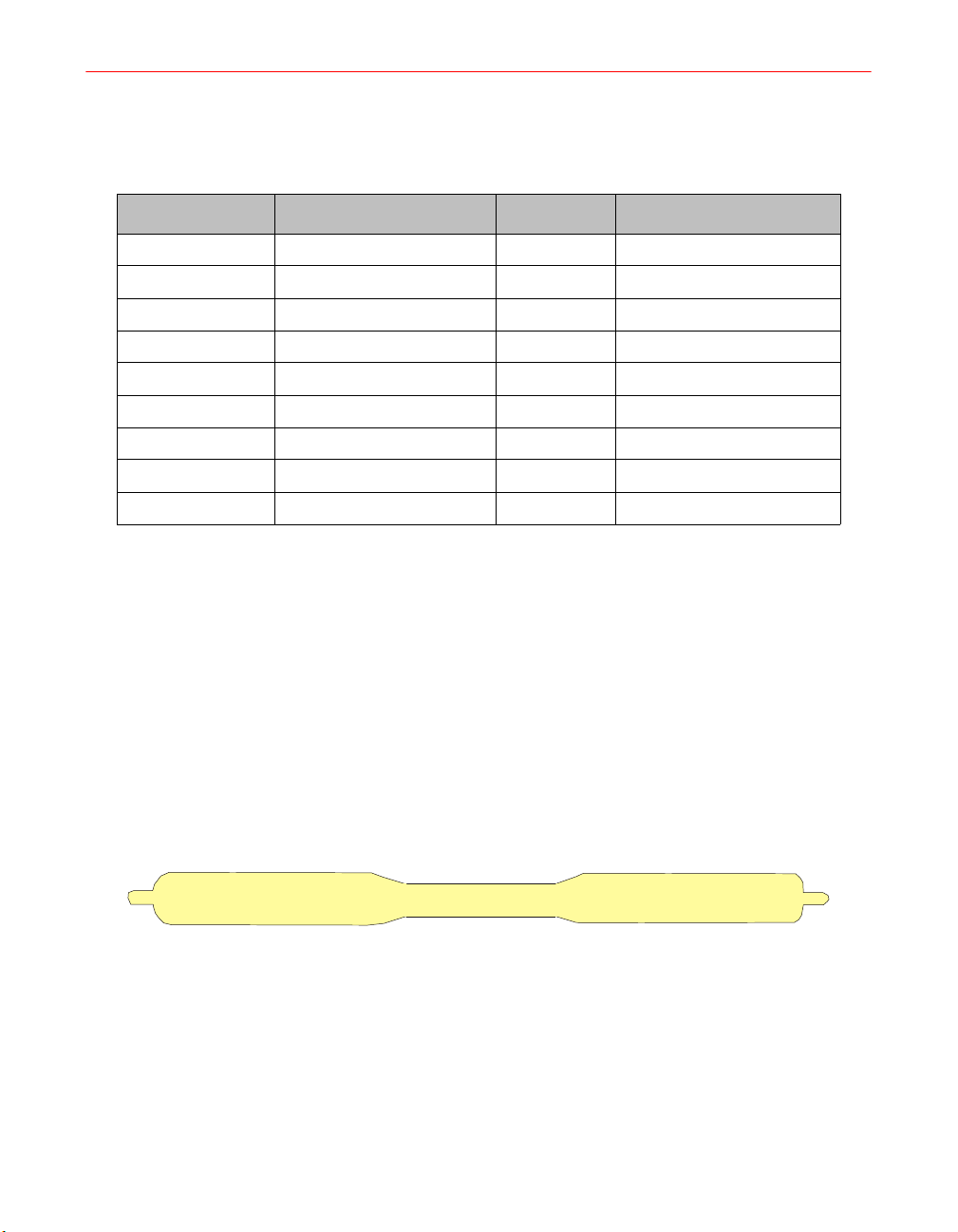
Lamp Bulb
The lamp bulb (Figure 3) is made of quartz and has a tapered shape which optimizes
its UV, thermal, and microwave properties. The short quartz stubs at either end of the
15.3 cm (6") bulb provide mechanical support for quick mounting into spring-loaded
receptacles at the cavity ends. They are not electrodes and have no electrical function.
Figure 3. Lamp Bulb
Access to the cavity for changing the bulb or routine cleaning of the bulb and reflector
is easily accomplished by removing the screws which secure the screen assembly to
the bottom of the lamp. This procedure is explained in detail in Chapter 6,
“Maintenance”. The fine mesh screen must be intact and firmly secured to the lamp if
the system is to work properly and safely. The RF leakage interlock automatically
shuts the system off if excess microwave energy passes through the screen.
Installation, Operation, and Maintenance Manual # 509252 Rev R 19

Mounting
The lamps can be mounted over a moving substrate or web, supported by the bottom
rails. The lamps should be mounted so that the rails sit 53 mm (2.1") above the surface
to be cured. This allows the elliptical reflector to focus the most intense strip of light
very near the substrate.
Power Supply
Each lamp system has its own power supply to house the high voltage circuits
necessary to energize the magnetron, as well as all control and interlock electronics,
and the built-in cooling fan.
The power supply is fully modular. Up to six units may be interconnected and
controlled from a single master unit. Any power supply may assume either Master or
Slave status in a multi-unit installation.
P300M/P300MQ/P300MT
The power supply high voltage circuit consists of a dual half-wave voltage doubler
circuit which supplies a regulated source of high voltage power (approximately
3900V, 700 mA DC) to the magnetron in the irradiator. The capacitors and diodes
provide regulation and rectification to the high voltage transformer outputs.
RF Detector
The system includes a detection device which shuts the system down if microwave
energy in excess of permissible levels is in danger of being released into the work
environment. This might be caused by a faulty RF screen or some other type of damage
to the lamp, or by inadequate or damaged shielding.
The power supply fault detection circuitry searches the system for a functioning RF
detector by means of the System Interconnections Bus. A multi-unit installation must
have at least one RF detector, which is usually connected to the master power supply.
Additional detectors may be connected to slave units.
During the startup sequence, each power supply will automatically perform a
functional test on any installed RF detector (if switch S1-5 is set to “YES”). The
operator may also verify detector operation by pushing a test button on the RF-1
module for 4 seconds. Complete information appears in Chapter 5, “Troubleshooting”.
System Interconnections
All electrical connections to the power supply are made through connectors at the rear.
Instructions for wiring are provided in Chapter 3, “Electrical System”. The power
supply does not require any routine maintenance other than occasional cleaning of the
interior with compressed air (depending on the environment).
20 F300S/F300SQ Ultraviolet Lamp System
Warranty Policy
Items manufactured by Fusion UV Systems Incorporated are warranted (under normal
and proper use) to be free from defects in material and workmanship. Fusion UV
Systems will repair or replace, at its option, any defective parts when returned to
Fusion by the purchaser, transportation paid. See the Terms & Conditions included
with your sales order for the length of the warranty period.
Equipment may not be returned, whether for warranty or other purposes, without prior
authorization and issuance of a Returned Material Authorization Number by Fusion
UV Systems. After inspection and acceptance, equipment returned for credit will be
subject to a handling and restocking charge.
Fusion UV Systems assumes no expense or liability for repairs made outside its plant
without written consent nor for any labor costs which are so incurred. For equipment
manufactured by others, Fusion UV Systems will pass along to the purchaser whatever
warranty it receives and will not be responsible for any incurred expense outside of
such warranty.
If repair of equipment is required but return of such equipment to Fusion UV Systems
is not feasible, then by mutual consent of Fusion and the purchaser, an authorized
Fusion UV service representative will be sent to the purchaser’s plant to effect
necessary repairs. The purchaser will be charged for the representative’s time and
expense.
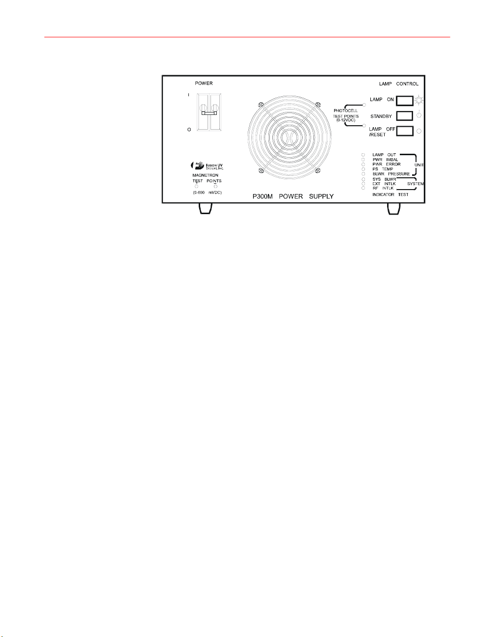
Figure 4. P300M Front Panel
The two consumable items in a Fusion UV lamp system are the lamp bulb and the
microwave power tube (magnetron). The special warranties on these components are
detailed on the sales contract.
Installation, Operation, and Maintenance Manual # 509252 Rev R 21

NOTE: Any repairs or alterations, including the use of non-Fusion UV
Systems (Fusion) parts, made by the user of this product without Fusion
UV Systems’ prior written consent shall void all warranties provided by
Fusion UV Systems and such warranties shall cease to be in effect. No
allowance will be granted for such repairs or alterations. No person,
agent, representative, or distributor is authorized to give any warranties
on behalf of Fusion UV Systems, or to accept for Fusion UV Systems any
other liability in connection with any of Fusion UV Systems’ products.
Shipping Instructions
Read the following sections carefully to ensure compliance with the requirements and
recommendations for returning products or components, whether for credit,
replacement, or repairs.
Returned Material Authorization Number
Equipment may not be returned, whether for warranty or other purposes, without prior
authorization and issuance by Fusion UV Systems of a Returned Material
Authorization Number. After inspection and acceptance, equipment returned for credit
will be subject to a handling and restocking charge. Returned equipment must be
shipped prepaid.
General Packing Instructions
If possible, original packaging materials should be reused for return shipment to
Fusion UV Systems. If Fusion UV Systems’ packaging materials are not used,
equivalent packaging, as outlined in the following sections, is to be used.
Power Supply
Secure the chassis to the cover by M5 x 12 mm screws. (There are three on each side
of power supply for the P300M/P300MQ, two on each side of power supply for the
P300MT.)
Box: Bursting Test: 24 kg/cm
Gross Weight Limit: 70 kg (155 lbs.)
Fills: Rigid high density styrofoam or cardboard fills as required to
CAUTION: Packaging materials should not push against connectors or
controls.
22 F300S/F300SQ Ultraviolet Lamp System
2
(350 lbs./sq. in.)
ensure power supply does not shift in box during shipment.

Irradiators
Irradiators should be returned in their original packaging. If this is not available, lamps
must be double boxed, as follows:
The lamp is to be placed in an inner box, using cardboard fills to assure a snug fit. The
RF screen should be protected by taping a piece of cardboard over it. The inner box
should then be placed in an outer box that provides about a two-inch clearance on all
sides. High density styrofoam corner pads should be placed in the corners between the
outer and inner boxes to isolate the lamp from impact.
Box: Bursting test: 24 kg/cm
Gross Wt. Limit: 70 kg (155 lbs.)
Magnetrons
If available, use a special Fusion replacement magnetron shipping box. Otherwise,
magnetrons must be double boxed as described next.
Wrap magnetrons in three layers of plastic “bubble wrap” or equivalent. Place
magnetrons in the box and add loose styrofoam fill. Place this inner box in an outer
box and surround the inner box with loose styrofoam fill.
UV Bulbs
2
(350 lbs./sq. in.)
Place the bulb in a rigid tube (use Fusion UV Systems’ plastic lamp bulb replacement
shipping tube if available.) Secure ends to prevent impact against the tube and wrap
the tube in three layers of plastic “bubble wrap” or equivalent. Ship with loose
styrofoam fill in the box.
Control Cards
The integrated circuits in control board assemblies are susceptible to damage from
static electrical charges which may be transmitted by handling or packaging materials.
To guard against static, place control cards in anti-static bags, if available. If not, wrap
control cards in aluminum foil. Isolate the cards from impact with additional wrapping
of “bubble wrap” or equivalent.
RF Detectors
RF Detectors should be wrapped in two layers of “bubble wrap” or equivalent and
placed in a box with loose styrofoam fill.
Installation, Operation, and Maintenance Manual # 509252 Rev R 23

24 F300S/F300SQ Ultraviolet Lamp System
Chapter 1. Safety
Fusion UV Systems’ Ultraviolet (UV) Lamp Systems have been designed to operate
safely. Many systems are in production in a wide variety of industrial environments
without any problems of worker safety or health hazards. However, like most
industrial equipment, this equipment can present worker safety problems if care is not
taken to install, operate, and maintain it correctly.
The following pages provide information concerning various aspects of worker safety
with regard to this equipment. Because some features of the system may be new to
personnel using the equipment, an attempt has been made to provide a fairly extensive
background on these issues as well as references, where feasible, to further information
or U.S. Government Standards.
Care in installation and operation, coupled with adequate worker training, should
ensure that no unusual safety problems arise.
IMPORTANT: All personnel using the equipment
must become familiar with this safety information.
Installation, Operation, and Maintenance Manual # 509252 Rev R 25
Ultraviolet Radiation
Ultraviolet radiation which is emitted during normal operation of the
Fusion Ultraviolet Lamp System can be dangerous to the eyes and
skin of personnel. Adequate shielding around the system and the
region to be irradiated must be provided. If unsafe levels of light are
allowed to escape during operation, then all personnel in the vicinity
of the lamps should be required to wear goggles with UV certified
lenses. Protection is needed for indirect as well as direct eye
exposure; UV certified lenses are recommended. Discomfort from
excessive eye exposure to ultraviolet light typically occurs about six
hours after exposure. Personnel who experience eye pain after
possible exposure to direct rays from the UV lamp should see a
doctor. Furthermore, in the event that adequate shielding is not
possible, all personnel within ten feet of the lamp should wear gloves
and long-sleeved shirts to protect hands and arms.
There are no present U.S. government standards on worker exposure to ultraviolet
light. However, there is a NIOSH document, “Criteria for a Recommended
Standard...Occupational Exposure to Ultraviolet Radiation” (No. HSM 73-11009),
and several useful publications are available from the Bureau of Radiological Health
of the Food and Drug Administration.
Microwave Radiation
The Fusion UV Lamp System is powered by high energy RF
microwave power. This form of energy is identical to that used in
home microwave ovens and, as in the case of ovens, can be
dangerous if misused or inadequately shielded. In the Fusion UV
lamp, the shielding is adequate only as long as the lamp and the
screen on the bottom of the lamp are intact. Any rip or large hole in
the screen may lead to microwave radiation leakage in dangerous
amounts. The power to the lamp is interlocked to shut off if there is
excessive microwave radiation leakage. The lamp system should
never be turned on if the lamp housing and screen are not intact, or if
the microwave leak detector and interlock are not functioning.
Fusion UV equipment is interlocked to shut down if microwave leakage in excess of 5
mW/cm
26 F300S/F300SQ Ultraviolet Lamp System
2
(milliwatts per square centimeter) is detected.
Personnel Effects of Microwave Radiation
OSHA (U.S. Department of Labor, Occupational Safety, and Health Administration Standard 29CFR 1910.97) and ANSI (American National Standards Institute Standard C95.1-1999) are the only major national organizations with voluntary
guidelines for safe limits of occupational microwave radiation exposure.
The ANSI recommendation is the more stringent of the two guidelines. Conservatively
expressed, it states that a worker should not be exposed to microwave radiation levels
in excess of 8 mW/cm
exposure to much higher levels by stating that over a six-minute period the average
power density to which a worker is exposed to microwave radiation should not exceed
8 mW/cm
2
.
Microwave radiation is considered a non-ionizing electromagnetic radiation, which is
not known to produce genetic damage. The primary effect of this energy is to simply
raise the temperature of a body which absorbs it. For example, 5 mW/cm
cc of water 0.07
level continuously, he would absorb about 30 watts over his whole body. At rest, the
body dissipates about 100 watts. Therefore, this additional heat load is considered safe,
although we do not recommend continuous exposure to levels anywhere near 5
mW/cm
2
.
2
on a continuous basis at 2.45 GHz. It allows for short-term
o
C in one minute. If the average worker were exposed to this energy
2
will raise 1
Fusion UV Systems equipment normally produces low level leakage well below
8mW/cm
2
in the work environment. If a microwave survey meter is used, one should
read levels well below 1 mW/cm
exposed. When a lamp is started, leakage levels may increase by a factor of two or
three for the few seconds it takes to start and couple energy to the bulb. This is
considered safe due to the requirement to average under 8 mW/cm
period.
Radio Interference
Fusion lamps operate at a fundamental frequency of 2.45 GHz. The unit may cause
interference with some local area networks (LANs) that also operate at this frequency.
Please check with your LAN manufacturer for compatibility.
2
where personnel are likely to be continuously
2
over a six-minute
Fusion UV lamps are classified as non-consumer industrial, scientific
and medical equipment, as defined in Federal Communication
Commission (FCC) Rules and Regulations Volume 47, Part 18. As
required by these rules, Fusion UV Systems verifies that their systems
are capable of compliance with applicable technical standards
governing radiated emissions when the equipment is properly
maintained and is installed in an appropriate light shield.
Installation, Operation, and Maintenance Manual # 509252 Rev R 27
Ozone
The Fusion UV Lamp System makes less ozone than a conventional arc lamp. For
example, a pair of lamps running for twelve hours in a non-vented room resulted in a
steady state concentration of less than 0.02 parts per million. This was a level that
could barely be detected by odor and a factor of five below the level of 0.1 parts per
million allowable for continuous exposure (American Conference of Governmental
Hygienists).
All Fusion UV Lamp Systems should be exhausted to the outdoors.
Temperature
Ozone is a gaseous form of oxygen which is formed by ultraviolet light. It
has a characteristic pungent odor to which most people are quite sensitive
(people can typically detect concentrations of several parts per hundred
million). At high concentrations it can cause discomfort or at sufficiently
high levels be dangerous.
Surface temperatures of the lamp during normal operation may
exceed 120
Before attempting service procedures on the lamp, allow the unit
to operate in STANDBY so that the blower continues to run. The
bulb will cool completely in less than one minute. If the blower
is not allowed to run, the bulb will retain heat for several
minutes. Observe appropriate precautions to avoid burns.
Handle the bulb with cotton or surgical gloves or a lint-free towel at all times, as
fingerprints can be etched into the quartz.
o
F. Metal components near the lamp will also be hot.
28 F300S/F300SQ Ultraviolet Lamp System
High Voltage
Insulated electrical cables carry power at 3900 Volts from the power supply to the
lamp. These voltages can be dangerous, so some precautions should be taken in both
the location and protection of these lines. High voltages are exposed within the power
supply chassis, which should never be operated without its cover.
DANGER: Never touch the power supply/lamp cable
connections while the system is ON or in STANDBY. A faulty
magnetron may cause 7000 Volts DC to appear on connector
pins and may cause serious injury.
Do not touch power supply/irradiator harness plug P10 near the
contacts, and do not lay P10 down on any conductive material.
Never troubleshoot the power supply without first disconnecting
all external power and discharging the high voltage capacitors
with an insulated screwdriver.
A high quality cable, rated at 10,000 Volts, is used in all high voltage cables
manufactured by Fusion UV Systems, and can be supplied to users for any additional
connections that may be required.
UV Curable Materials
Please consult your UV materials supplier for recommended precautions regarding the
proper handling and use of these products.
Installation, Operation, and Maintenance Manual # 509252 Rev R 29

30 F300S/F300SQ Ultraviolet Lamp System

Chapter 2. Mechanical Installation
Mechanical Installation Checklist
Before operating the ultraviolet lamp system for the first time, be sure the following
procedures have been completed.
Table 3. Mechanical Installation Checklist
Item Chapter
Review safety procedures Chapter 1, “Safety”
Light shields in place “UV Light Shielding” on page 34
RF detector positioned correctly “RF Detector Mounting” on page 35
Fan connection for exhaust of light shield “Remote Blowers” on page 36
RF screen and lamp bulb inspected Introduction, page 11
This chapter describes the physical installation of the F300S/F300SQ Fusion UV
Lamp System. Directions regarding mounting and shielding of the system are
somewhat general because they will vary depending upon the details of each
individual installation.
Unpacking and Inspection
This Fusion UV lamp system has been thoroughly tested inspected, and packed prior
to shipment. Before unpacking, examine all shipping containers for damage. After
unpacking, examine the equipment for damage. Any damage should be reported
immediately to the shipper and to Fusion UV Systems Incorporated. A delay of more
than 10 days may invalidate future claims for damages.
CAUTION: Irradiators are particularly vulnerable to dust, dirt, metal
chips, and RF screen damage. They are shipped with a protective
covering over the screen. The covering should not be removed until just
prior to installation.
When unpacking, identify and compare each item with the packing list enclosed.
Remember to examine each component for damage. Appendix E, “Replacement Parts”
details the items included with the system which will be required to complete the
installation.
Installation, Operation, and Maintenance Manual # 509252 Rev R 31
Preliminary unpacking and inspection should be completed immediately on receipt of
equipment to allow time for repair or replacement if necessary prior to installing the
equipment.
The P300M/P300MQ power supplies are shipped with six large Phillips head screws
holding the cover to the chassis. There are three screws located on each side. The
P300MT power supply is shipped with four large Phillips head screws holding the
cover to the chassis. There are two screws located on each side of the P300MT.
The four or six cover screws
must be in place before
operation to maintain continuity
of the power supply enclosure
ground circuit.
After the inspection is completed, all components must be carefully re-packed and
stored until actual installation. Save the packing materials. They will be valuable if any
component must be returned to Fusion UV Systems for service. See “Shipping
Instructions” on page 22 for more information.
Power Supply Unit(s) Placement
The mechanical installation of a power supply unit is almost entirely at the user’s
convenience. It can be placed on a sturdy shelf or in a cabinet provided that
approximately 30 cm (12 inches) of space is left behind the power supply for cooling
air to escape, and so that the cable harnesses can be run to the other components. See
Appendix C, page 129 for restricted space clearance minimums.
The P300M/P300MQ power supplies can function in any position, although standard
horizontal mounting is recommended. Mounting the power supply so that the control
panel is facing upward is not recommended because this allows dirt and dust to settle
into the unit. In this position, the horizontal surface that is provided by the inlet finger
guard also can be easily blocked by papers, notebooks, or other flat materials that will
cause thermal overload and system shutdown.
Power supplies are stackable up to three (3) units high. However, a power supply can
weigh up to 40.3 kg (88.6 lbs.), so units should not be stacked to, or installed at, a
height that makes access of chassis removal difficult.
32 F300S/F300SQ Ultraviolet Lamp System
Irradiator Mounting
The irradiator mounting structure must also provide UV shielding and adequate
venting for the cooling air. This is described on the following pages. Each user will
normally design the mounting structure to suit the particular application, and the user
is responsible for providing the required shielding and ventilation. (Irradiator
dimensions are shown in Appendix C, “Outline Drawings” and detailed in the
Appendix A, “Specifications”.
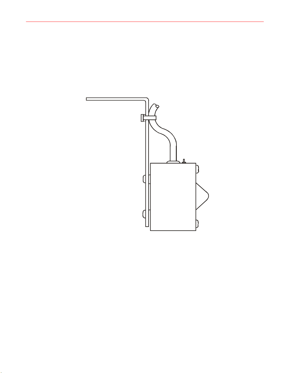
The easiest and most common mounting position is with the irradiator vertical and the
screen at the bottom 53 mm (2.1 in.) above the substrate. Simply rest the module on a
pair of angle irons oriented in the same direction as the lamp bulb. One common
mounting scheme is shown in Figure 5.
Vertical mounting requires that no part of the support can push against the irradiator
screen, causing it to tear. Provisions may be made for raising or lowering the support
structure with respect to the substrate to be irradiated. This allows the user to optimize
the curing by working in focus or somewhat out of focus.
Figure 5. Vertical Mounting Design for Irradiators
Installation, Operation, and Maintenance Manual # 509252 Rev R 33
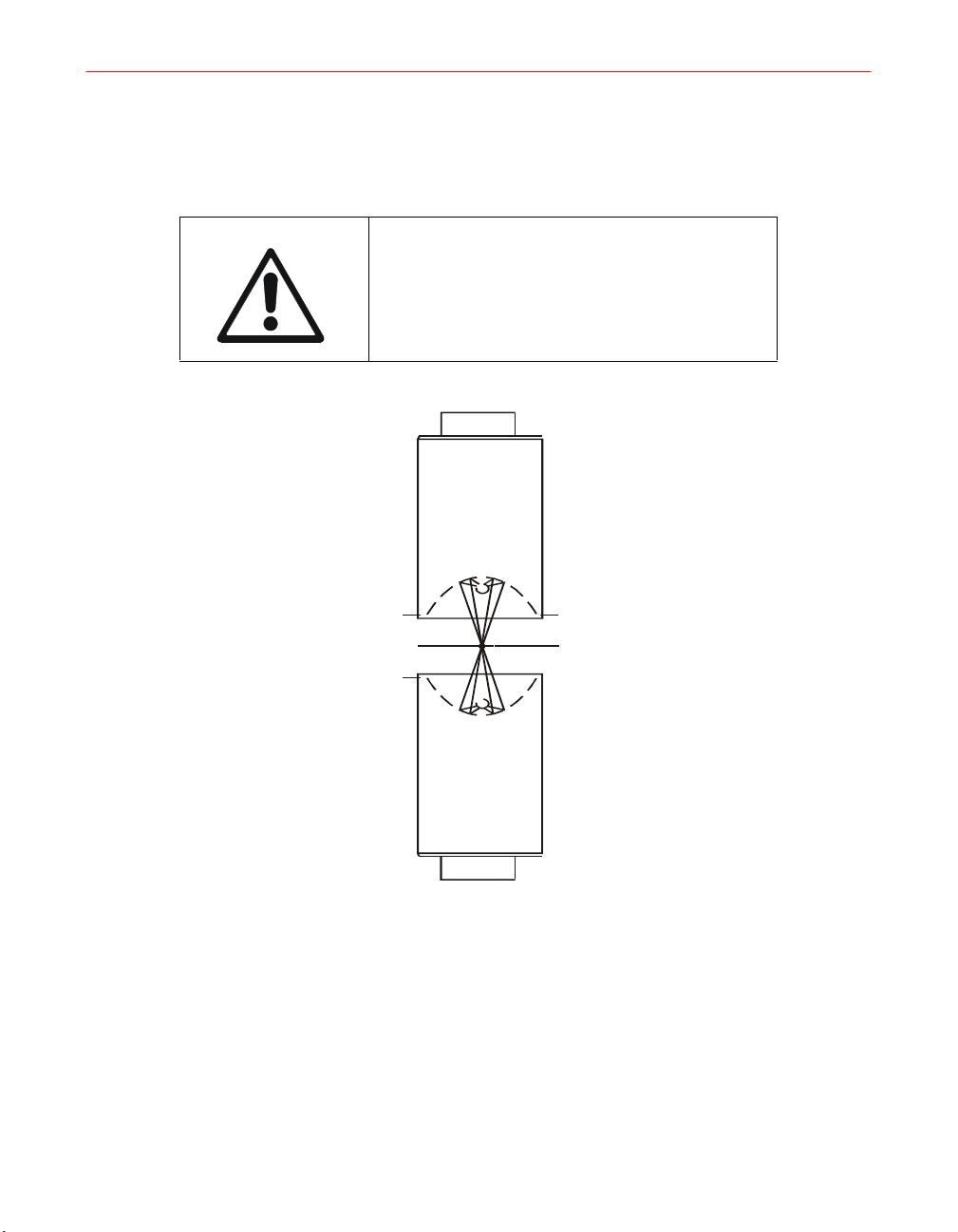
Lamps Mounted in Opposing Configuration
IMPORTANT: If two lamps are to be mounted
opposing each other (as shown in Figure 6 on
page 34), lamp performance and operation
may be impaired. Contact Fusion UV Systems
Technical service department for consultation.
Figure 6. Lamps in Opposing Configuration
UV Light Shielding
Adequate light shielding must be provided for each irradiator in the system. If
shielding is not used, or if UV light escapes around the irradiator support, the operator
must wear a welder’s helmet or UV blocking eye wear. Long sleeved clothing is
required to protect the skin from the effects of UV light.
34 F300S/F300SQ Ultraviolet Lamp System
The louvers which allow the flow of cooling air away from the irradiator must be of a
light shielding design.
(For more information on safety considerations, see Chapter 1, “Safety.”)
RF Detector Mounting
Figure 7 illustrates the proper mounting of the RF Detector.
Figure 7. Fusion UV Systems RF Detector RF-1
One RF detection device must be installed for each light shield. The antenna should
point toward the irradiator screen, which is the potential source of RF leakage.
However, to protect the antenna from heat and UV light, it should be placed outside
the light shield. It may “look” into the light shield through an existing opening, or one
made for this purpose. The tip of the sensing cone should be at least two inches from
the opening of the light shield.
The presence of metal surfaces near the detector may cause false readings; allow a
maximum open area around the device.
The connection of the cable from the RF detector to the power supply is explained in
Chapter 3, “Electrical System”.
Installation, Operation, and Maintenance Manual # 509252 Rev R 35

Remote Blowers
An optional remote blower package is available from Fusion UV Systems. The
package includes an air distribution plenum (for multi-lamp systems), inlet filter box,
and flexible hoses or ducts for cooling the system. The blower delivers 2.8 m
(100 cfm) of air to each irradiator inlet at 695 Pa (2.8" H
“Maintenance” for information on the measurement procedure.
Irradiator Exhaust Venting
Fusion UV Systems recommends that 3.6 m3/min (130 cfm) of air be exhausted from
each irradiator. The air flow must be vented below the irradiator to prevent back
pressure buildup, which would reduce the flow of cooling air. An exhaust fan is
recommended to draw hot air and ozone away from the UV lamp and discharges them
to the outside. The fan must remove at least 30% more air than is supplied to the
irradiator inlets so a negative pressure will exist under the lamps. The makeup air
enters through the UV shielding louvers or any other vents in the light shielding
enclosure.
Light shielding louvers are recommended. At least 142 cm
area is recommended for each irradiator to allow free flow of make-up air. If the
exhaust air is not vented outside the building care should be taken to prevent it from
recirculating into the inlet of the blower(s).
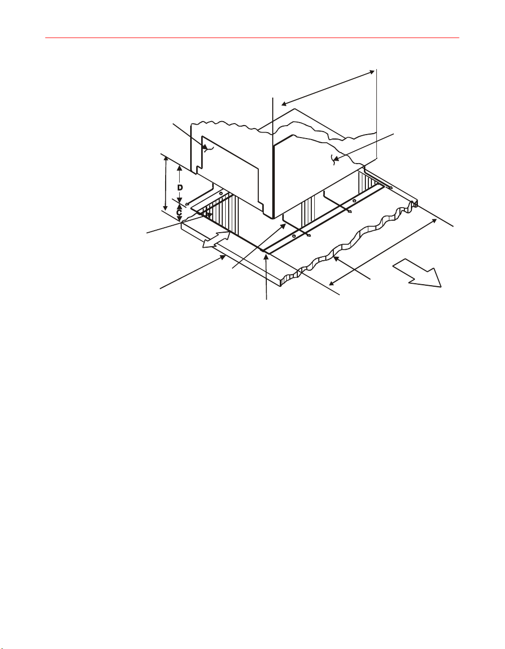
Quartz Plates
O). See Chapter 6,
2
2
(22 sq. in.) of louvered
3
/min
To protect the material being cured, quartz plates may be mounted below the UV lamp
to block the air carrying heat away from the bulb. A typical mounting design is shown
in Figure 8 on page 37. Details of the mounting structure depend upon the position and
location of the irradiator and UV shielding.
Clearance C prevents the substrate from striking and breaking the quartz plate but
varies with the application. Distance D should be at least one inch and as large as
practical to provide maximum area for the escape of cooling air (see Figure 8 on page
37).
36 F300S/F300SQ Ultraviolet Lamp System
m
m
6
.
7
6
)
1
0
6
.
6
(
Irradiator
53.3mm
(2.10)
Quartz plate (pair) P/N 300291
152.4 mm x 152 .4 mm x 2.29 mm
(6.00 in x 6.00 in. x 0.90 in.)
Removal access
for cleaning
Figure 8. Quartz Plates - Example Mounting Design
Irradiator
cooling
air flow
Quartz plate
mounting structure
m
m
2
5
1
0
.
6
(
Substrate
to be cured
Irradiator
mounting
structure
support
)
0
Installation, Operation, and Maintenance Manual # 509252 Rev R 37

38 F300S/F300SQ Ultraviolet Lamp System
Chapter 3. Electrical System
This chapter discusses the electrical installation and electrical setup aspects of the
F300S/F300SQ Ultraviolet Lamp System.
Electrical Installation/Setup Checklist
Before operating the ultraviolet lamp system for the first time, be sure the following
items have been reviewed and/or tested.
Table 4. Electrical Installation and Setup Checklist
Item Chapter
AC input voltage matches equipment label and
connected correctly
Power supply HV capacitors tapped for AC line
frequency
Power supply HV transformers correctly tapped for AC
input voltage
Chapter 3, “Electrical System”
Chapter 3, “Electrical System”,
page 51
Chapter 3, “Electrical System”,
page 51
Programming correct for each unit Chapter 3, “Electrical System”,
page 43, page 44
Interconnection cables secure Chapter 3, “Electrical System”,
page 44, page 49
RF cable secure Chapter 3, “Electrical System”,
page 45, page 49
User inputs (EXTERNAL INTERLOCK, SYSTEM
BLOWER) connected if wanted
Remote inputs (RESET, LAMP ON) connected if
wanted
User outputs (FILAMENT ON, HV ON, FUTURE USE,
LAMP ON, and PRESS ENABLE) connected if wanted
Chapter 3, “Electrical System”,
page 40
Chapter 3, “Electrical System”,
page 45
Chapter 3, “Electrical System”,
page 46
Review normal operating procedures Chapter 4., Operation, on page 55
Accessory Parts List
The Accessory Parts List is located in Appendix E, “Replacement Parts,” and should
be reviewed when setting up your system.
Installation, Operation, and Maintenance Manual # 509252 Rev R 39
Interconnect Cables
The F300S/F300SQ interconnect cables and connector contact kits are listed in
Appendix B, “Cables and Connectors”. See this list for the available varieties and
lengths.
Connection and Program Log
To facilitate operation and maintenance, it is advisable to keep a record of the
input/output connections and programming used on each unit. A blank log form is
included in Appendix D, “Lamp System Maintenance Log” of this manual.
Installing the External Interlocks Control
An input has been made available for use as an external interlock control. When
activated, this circuit will cause the system to shut down. (See Chapter 5,
“Troubleshooting” for details.)
User Connections
Pin removal and crimping tools are required to complete the optional user input/output
connections to P105A and P106. Make these connections as described next.
J105A
INTERLOCKS
J105B J107
(K1-K5)
J106
BUS INPUT
BUS OUTPUTRELAYS
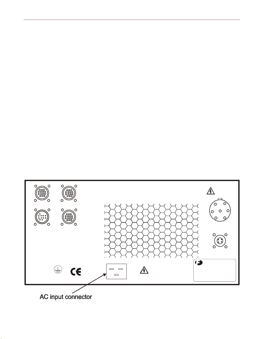
Figure 9. P300M/P300MQ Power Supply Rear Panel
40 F300S/F300SQ Ultraviolet Lamp System
J101
DISC ONNECT POW ER
BEFORE SERVICI NG
J103
HIGH V OLTAGE CABLE
J104
IRRADIATOR
BLOWER CABLE

1. Disassemble the strain relief housing by removing the retaining screws and
unscrewing the housing from the connector body.
2. To connect EXT INTLK or SYS BLWR inputs, remove jumper wires and the
attached pins as indicated in Table 5, Table 6, and Table 7 in this chapter.
3. With a crimping tool, attach wires from user devices to new pins (supplied with
system) and insert the pins in the proper locations.
4. Reassemble the strain relief housing.
Power Supply Programming
P300M/P300MQ/P300MT power supplies may be interconnected to form a complete
system of up to six lamps. Through use of the System Interconnections Bus control
functions, the entire system may be operated by the lamp control switch of one master
power supply, or by a switch on an external control panel.
See Figure 10 on page 42 for the location of programming switch S1. To access S1,
remove the six screws on the side of the power supply cover. For programming switch
S1 settings, see the table illustration in Figure 11 on page 43.
Settings for Six-Position Switch S1
Positions 1, 2, and 3 of S1 (see Figure 10) must be set to determine whether a power
supply is a master or a slave.
Position 4 determines whether a unit fault will turn off all power supplies or only the
unit where the fault occurs.
Position 5 indicates to the system bus whether a power supply (either the master or a
slave) has an RF Detector connected to it. (There must be at least one RF Detector
connected to a system.)
Installation, Operation, and Maintenance Manual # 509252 Rev R 41

TP2
TP1
DS1
JP2
S2
J1
J14
J15
J16
J2
OFF/RST MASTER
ON MASTER
HI / LO MASTER
UNIT TO SYS
RF MASTER
J5
J3
J4
S3
F2
F1
S1
QRO
ASSY P/N 32755X
K1
K2
J11
K3
J6
J7
J8
K4
K5
Figure 10. Location of Programming Switch S1 on PWB
J9
J10
F3q0008
42 F300S/F300SQ Ultraviolet Lamp System

Switch Position
1, 2, and 3
POS6POS5POS4
Figure 11. Table A: Programming Switch S1
Single Unit Programming and Connections
The programming and connections necessary to operate a single-unit F300S/F300SQ
system are summarized in Figure 12.
Installation, Operation, and Maintenance Manual # 509252 Rev R 43

Figure 12. F300/F300SQ Single-unit Installation
Programming
Select one unit as the Master. Set S1-1, 1-2, 1-3, and 1-5 of this unit to “YES.” For
programming switch S1 setting definitions, see Figure 11.
Irradiator Cable H340 Connections
Non-blower version cable H340 connects to J103 and J104 on the power supply; and
to J10 on the irradiator. All connectors are labeled, and keyed so they cannot be
inadvertently interchanged.
Blower version cable H341 connects to J103 and J104 on the power supply, and to J10
and J11 on the irradiator. All connectors are labeled, and keyed so they cannot be
inadvertently interchanged.
44 F300S/F300SQ Ultraviolet Lamp System

Input/Output Connections
The P300M/P300MQ/P300MT has three customer use interlock inputs. A fault
condition on any of these inputs will cause the system to shut down; the fault must be
corrected before the system can be restarted.
There must be one RF detector per system. The remaining interlock inputs are
optional. The system blower and external interlock inputs in the P105A connector
must be jumpered if these inputs are not used.
NOTE: All external switches must have gold contacts or be designed for use
with logic-level signals to ensure reliable operation.
Table 5. J105A Inputs
Interlock Pins
RF Detector
(Master)
RF Detector
(Slave)
SYS Blower 11,12 OPEN
External
Interlock
1,2,3,4 RF trip or
3,4 OPEN
9,10 OPEN
Fault
Condition
no detector
present
CIRCUIT
CIRCUIT
CIRCUIT
Remote Inputs
One switch is required for remote operation of an F300S/F300SQ (to control the
STANDBY/LAMP ON functions). Connections are made through the P106 connector.
Single or Master/Slave systems may be operated remotely.
(Customer Use Interlocks)
Contact
Ratings
12mA @12 VDC Single lamp: One detector per system
Multiple lamps: RF Master must have
RF detector.
12mA @12 VDC Single lamp: N/A
Multiple lamps: Typically jumpered. User
should remove jumper to install
additional RF detectors and set S1-5 to
ON (Yes)
12mA @12 VDC Typically jumpered. User may remove
jumper to install N.O. pressure switch.
Multiple switches should be wired in
series.
12mA @12 VDC Typically jumpered. User may remove
jumper to install N.O. interlock switch.
Multiple switches should be wired in
series.
Application Comments
Installation, Operation, and Maintenance Manual # 509252 Rev R 45

NOTE: A dry contact (such as a relay contact or a PLC containing a relay
contact) with gold contact material should be used to drive the remote inputs.
The cable length to the dry contact should be no more than 6 meters. Shielded
cable should be used to minimize possible electrical interference.
In a multi-lamp system, connections are made to the Master power supply.
If there is a requirement for clearing faults remotely, a Remote Reset switch must
be used.
Table 6. J106 Inputs (Remote Operation)
Signal Pins
REMOTE
LAMP ON
REMOTE
RESET
CABLE
SHIELD
Active
Condition
4,5 Closed circuit 12mA @12 VDC Set switch S1-2 of Master
1,2 Closed circuit 12mA @12 VDC Set switch S1-1 of Master
8 N/A N/A Keep cable length to a
Contact
Ratings
Output Ports (J105B)
There are five relay outputs available on the P300M/P300MQ/P300MT through
J105B. These outputs may be used to synchronize customer equipment with the
system. In a multi-lamp system, connections are made to the Master power supply.
Table 7. J105B Outputs (Customer Interface)
J105B
Filament ON (K1) 3, 4 Closed 1 A @120 VAC
HV ON (K2) 5, 6 Closed 1 A @120 VAC
QRO 7, 8 Closed 1 A @120 VAC
Asserted
State
Circuit Ratings Comments
(10mA minimum)
(10mA minimum)
(10mA minimum)
Application Comments
to NO. Leave S1-1 and
S1-5 set to YES.
to NO.
minimum.
K1 contacts close when filament
voltage is applied (STANDBY).
K2 contacts close when high
voltage is applied to lamp.
K3 contacts close when QRO is
active.
46 F300S/F300SQ Ultraviolet Lamp System

Table 7. J105B Outputs (Customer Interface) (continued)
J105B
LAMP ON (K4) 9, 10 Closed 1 A @120 VAC
PRESS ENABLE
(K5)
11, 12 Closed 1 A @120 VAC
Asserted
State
Circuit Ratings Comments
(10mA minimum)
(10mA minimum)
NOTE: When using circuit currents for K1-K5 below 10mA, contact Fusion UV
Systems Customer Service.
Alternate Function for K5
An alternate K5 function may be selected by installing a jumper onto JP2 on the
control card. The STANDBY-READY function is asserted (K5 closed) when the
power supply completes the transition from the STANDBY-WAIT (flashing yellow)
to the STANDBY-READY state (steady yellow). K5 remains closed for the LAMP
ON state (flashing or steady green), the QRO state (alternate flashing of yellow and
green), and the return to the STANDBY-READY state (steady yellow). K5 opens
during the OFF/RESET state and the STANDBY-WAIT state (flashing yellow) from
either the LAMP ON state or from the OFF/RESET state.
K4 contacts close when photocell
is satisfied. Note: If using K4 for
press control, wait 6-8 seconds
for lamp output to stabilize.
K5 contacts remain closed when
no unit or system error exists.
STANDBY
READY
(K5 alt.)
Table 8. Alternate Function for K5
J105B Asserted State Circuit Ratings Comments
11, 12 Closed 1 A @120 VAC
(10mA minimum)
Installation, Operation, and Maintenance Manual # 509252 Rev R 47
K5 contacts close once
STANDBY-READY state is
achieved, and for any higher
state.
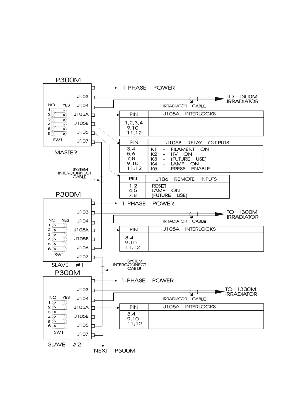
Multiple-Unit Programming and Connections
Programming and connections for multiple-unit systems are summarized in Figure 13.
Typically, one unit will operate as the MASTER and all others as slaves to the
ON/OFF commands of this Master unit. Refer to detailed descriptions in Chapter 4,
“Operation” of this manual.
RF DETECTOR
EXT. INTERLOCK (JUMPERED)
SYSTEM BLOWER (JUMPERED)
Figure 13. F300S/F300SQ Multiple Unit Programming & Connections
48 F300S/F300SQ Ultraviolet Lamp System
RF DETECTOR (JUMPERED)
EXT. INTERLOCK (JUMPERED)
SYSTEM BLOWER (JUMPERED)
RF DETECTOR (JUMPERED)
EXT. INTERLOCK (JUMPERED)
SYSTEM BLOWER (JUMPERED)
F3q0011

Programming
Refer to Figure 11 for programming switch S1 settings and set programming switches
of each power supply as follows:
1. Select one unit as the Master. Set S1-1, 1-2, 1-3 and 1-5 of this unit to YES.
2. Set S1-1, 1-2, 1-3, and 1-5 of all slaves to NO.
3. To shut down all units in case of a single-unit fault, set S1-4 on all units to YES
Connections
The following procedure describes how to connect multiple power supplies
(master/slave) within a system.
1. For proper operation, including fault detection, connect each power supply to the
2. Install input/output plugs P105A (with jumpers - provided with system) in
3. The Master power supply must have an RF Detector connected to J105A;
(For a detailed explanation of unit faults, see Chapter 4, “Operation.”)
next using the H760 interconnect cables supplied with the system. Cables run
from J107 of one unit to J106 of the next.
J105A of slave units.
additional RF detectors may be plugged into J105A of the Slave power supplies
by replacing the jumpered plug with the RF detector cable connector.
4. Make interlock connections to the Master using the P105A plug on RF detector
cable harness as indicated in “Input/Output Connections” on page 45 in this
chapter.
NOTES: When installing additional RF detectors on slave power supplies, be
sure to set S1-5 to YES on those power supplies.
If additional RF detectors are used, an RF fault in a slave will automatically be
interpreted as a system fault; this will shut down the entire system.
Additional interlocks such as RF, Remote Blower, and External Interlock may
be connected to a SLAVE unit through P105A. Remove any factory-installed
jumpers.
Installation, Operation, and Maintenance Manual # 509252 Rev R 49
Power Source
NOTE: If a line voltage greater than 230V and a frequency of 50 Hz is used, see
the “F300S Relay Coil Resistor Assembly Installation” on page 53 at the end of
this chapter.
System Power Connections
CAUTION: Measure the main single-phase voltage
of your plant facilities to ensure that it conforms to
the factory-wired operating voltage specified on the
equipment label (rear panel of power supply).
Available line voltage should be within 10% of the
nominal operating voltage.
Fusion UV equipment must be connected in
accordance with local wiring codes. Use applicable
standards for wire sizes, fuse sizes, and disconnect
box locations. Each power supply requires a
separate, fused single-phase circuit with a line
disconnect.
Figure 14. Power Supply Front Panel
Listed current ratings indicate current demands during normal full-power operation.
Your customer-supplied wiring and circuit breaker or fuses should be sized to allow
for heavier current draw at startup. Current ratings are the same for 50 Hz or 60 Hz
systems. The recommended power cord to wire to P101 is:
50 F300S/F300SQ Ultraviolet Lamp System
F3q0004
North American Applications: 3x12 AWG UL listed
International Applications: 3x2.5 mm
Both cable types should have minimum ratings of 16A, 300V, 0-60 °C.
Refer to Table 11 on page 57 in Chapter 4, “Operation,” for the leg currents for each
power supply/voltage combination.
Frequency Tapping of HV Capacitors
If it becomes necessary to configure the system for a line frequency other than that
delivered, the following steps should be followed:
1. Turn the unit POWER switch OFF and unplug the power cord.
2. Remove the power supply cover (six screws).
3. Locate the HV capacitors C101 and C102 (refer to Figure 15 on page 54).
4. Discharge the capacitor by shorting the capacitor terminals with an insulated
screwdriver.
5. Locate the jumper connected to the T terminal of each capacitor.
6. Disconnect the opposite end of this jumper from the capacitor terminal to which
it is connected, and reconnect it to the appropriate terminal for the desired line
frequency (50 for 50 Hz, 60 for 60 Hz).
2
Harmonized, VDE
QRO HV Capacitors (For QRO only)
When the Quick Restart Option is installed, one element of the retrofit is the
replacement of the HV capacitors. These HV capacitors are a different value than the
standard HV capacitors, but the frequency tapping procedure is exactly the same.
High Voltage Transformer Taps
Standard high voltage transformers have labeled taps. Power supplies are shipped with
transformers tapped according to customer power specifications. If a unit is relocated
or a transformer must be replaced, connections should be installed as shown in the
following table.
Table 9. High Voltage Transformer Taps
Power
Installation, Operation, and Maintenance Manual # 509252 Rev R 51
HV Plate
Transformer
Primary Tap
Table 9. High Voltage Transformer Taps (continued)
50 Hz
60 Hz
Power
200
208
220
240
200
208
220
240 220, 240
Transformer
200
220, 240
200
QRO Transformer Taps (FOR QRO only)
When the Quick Restart Option is installed, the QRO transformers must be tapped
according to the frequency and voltage specifications of the customer. Should these
specifications change, or if a transformer is replaced, the transformer should be tapped
as follows:
Table 10. QRO Transformer Taps (Optional)
QRO Transformer
Power
Primary Front Tap
HV Plate
Primary and
Secondary Rear Taps
200
50 Hz
60 Hz
52 F300S/F300SQ Ultraviolet Lamp System
208
220
240
200
208
220
240
200V
50 Hz
240V
200V
60 Hz
240V

F300S Relay Coil Resistor Assembly Installation
The relay coil resistor assembly must be used if the line voltage and frequency used
with a P300M/P300MQ/P300MT power supply is 230-240 VAC at 50 Hz (nominal
voltage). These resistor assemblies prevent the premature failure of the relay coils in
high line voltage environments. There are two coil resistor assemblies available in a
retrofit kit (See Appendix E, “Replacement Parts”). One assembly is placed in series
with each of the coils of K101 and K102 in the power supply. These resistors should
also be used when it becomes necessary to configure the system for a line voltage and
frequency of greater than 230 VAC at 50 Hz (nominal voltage.)
Installation Instructions
1. Turn off the power and disconnect power from the power supply.
2. Remove the six cover screws and cover from the P300M/P300MQ power
supply. (Remove the four cover screws and cover from the P300MT power
supply.)
3. Locate relays K101 and K102. K101 is closer to the rear of the power supply
and K102 is closer to the front (refer to Figure 15 on page 54).
4. On K102, locate tab 0. A black wire with a pink-insulated terminal will be
connected to it.
5. Disconnect the black wire and press the pink-insulated female terminal of one
resistor assembly onto K102 relay tab 0.
6. Connect the black wire with the red-insulated terminal to the red male terminal
of the resistor assembly. The leads of the resistor assembly should be bent to
form a U shape to make this connection easier.
7. On K101, locate tab 1. Two black wires with pink-insulated terminals will be
connected to it.
8. Disconnect the black wire with the fully insulated right-angle terminal and leave
the double terminal with the pink insulation connected. Press the female terminal
of the remaining resistor assembly onto the exposed tab of the double terminal.
9. Connect the right-angle terminal to the male terminal of the resistor assembly.
The leads of the resistor assembly should be bent to form a Z shape to make this
connection easier.
Installation, Operation, and Maintenance Manual # 509252 Rev R 53
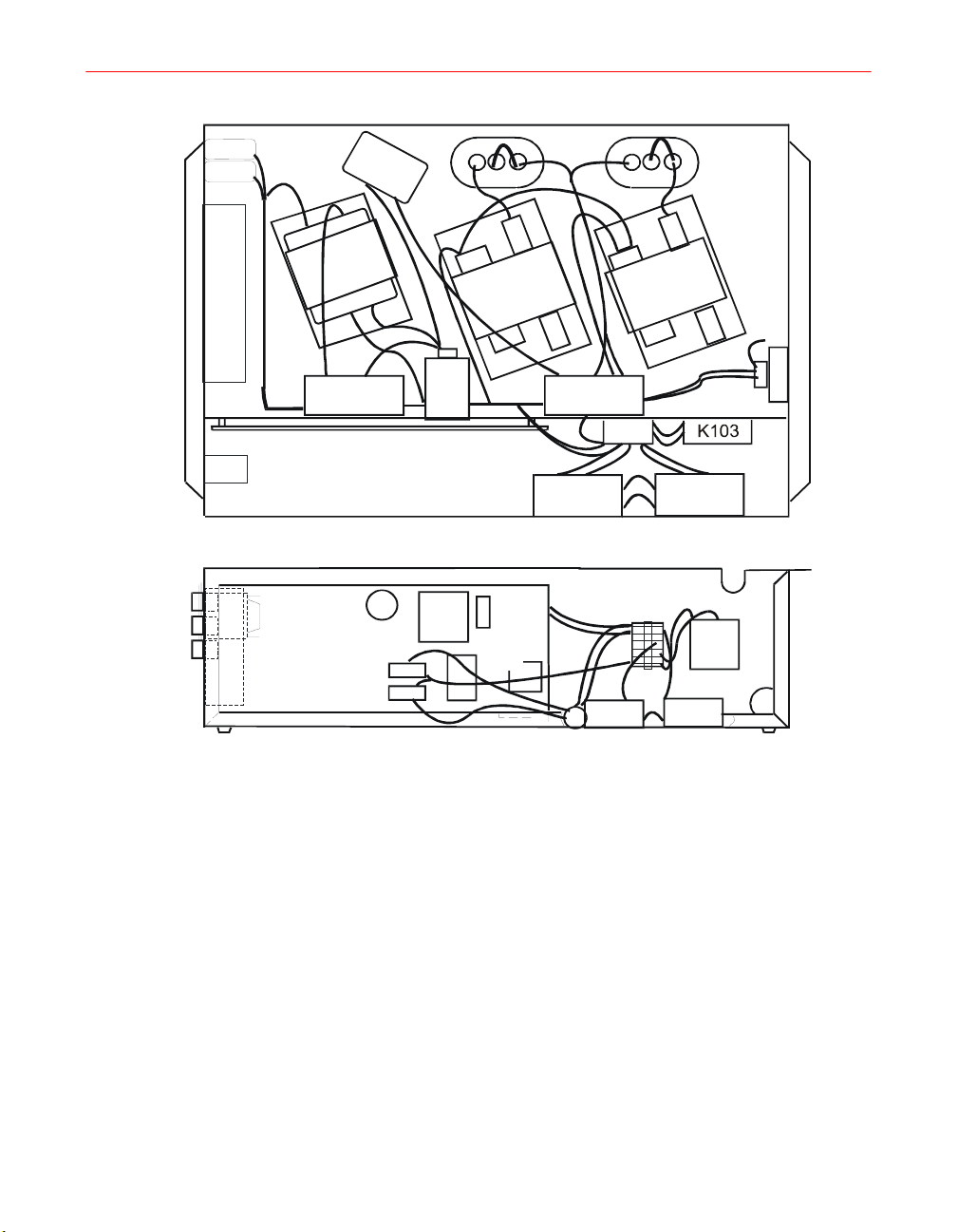
CB1A
CB1B
L101
C102
C101
Front
Front
S1
S2
S3
B101
T103
T102 T101
C103
DB1DB2
K102
Top V i e w
Side View
TB1
K102
Rear
J101
K101
T
B
1
K103
K101
Rear
Figure 15. K101 and K102 on P300M/P300MQ
54 F300S/F300SQ Ultraviolet Lamp System
Chapter 4. Operation
WARNING: Before operating the system, the
operator must become familiar with the operating
safety information presented in Chapter 1, “Safety”.
System Operation Controls
The lamp system is operated from the controls on the front of the power supply.
NOTE: Ambient system operating temperature is 0 to 45°C.
Lamp Control
At STANDBY, power (115 VAC) is applied to the magnetron filaments without
energizing the bulb. All interlocks and controls will continue to operate in STANDBY.
An external blower can be triggered through a connection to output relay K1.
Pressing the LAMP ON button energizes the lamp to its full power level after a
STANDBY delay and an additional “full power” delay. If after 8 seconds in the ON
position the bulb has not successfully ignited, the lamp will shut down. Check the LED
display on the power supply; it will indicate the probable source of the problem.
A “LAMP OUT” is a result of many different causes. The following are some reasons
that may be a source of this fault condition:
• Successive short cycles
• Operation at improper air pressure
• Operation at continuous reduced power level with improper air pressure
• Improper initial ignition of the system
• Poor distribution of the fill material inside the bulb as a result of shipping and
handling
Installation, Operation, and Maintenance Manual # 509252 Rev R 55

• Bulb producing insufficient output to activate the photocell
For proper initial ignition, the recommended “MINIMUM LAMP ON” time required
for this system is “ten (10) seconds” at normal air pressure (3.5 inches w.c.) and full
power operation (100% power level).
As previously mentioned, a “LAMP OUT” fault can occur when the bulb does not
reach sufficient output to activate the sensing photocell. This will particularly occur at
initial startup of the system, after successive “short cycles” (LAMP ON times below
10 seconds), or at the initial startup of a new bulb. In these instances, the bulb fill
material has not completely vaporized. With repeated attempts to start the system, the
problem may become worse, and can reduce the life of the electrical components.
Refer to Chapter 5, “Troubleshooting” for other possible causes of a LAMP OUT
condition.
Power
With the POWER switch in the OFF position, neither the control card nor the high
voltage circuitry are energized. With the switch in the ON position, the power supply
cooling fans and the control card are energized, and the LAMP Control switches are
enabled.
Off/Reset Control
When a fault occurs, the fault must be corrected and the unit(s) reset by pressing the
LAMP OFF/RESET switch before operation can be resumed.
1. If a UNIT fault occurs, correct and reset the individual unit.
2. If a SYSTEM fault occurs, reset the Master unit.
3. If a slave has an RF detector connected, reset the Master when the Slave
indicates a fault.
4. If a system is operated by a remote ON/STANDBY switch, reset the MASTER
power supply when a system fault occurs.
5. If a system uses a remote LAMP OFF/RESET switch, that switch may be used
instead of the front panel switch to reset a fault.
Initial Startup Procedure, Single Unit
1. Turn POWER switch to ON position and press the LAMP OFF/RESET switch:
The red LAMP OFF indicator is lit.
2. Press the STANDBY switch: the yellow STANDBY indicator blinks, then stays
lit.
56 F300S/F300SQ Ultraviolet Lamp System
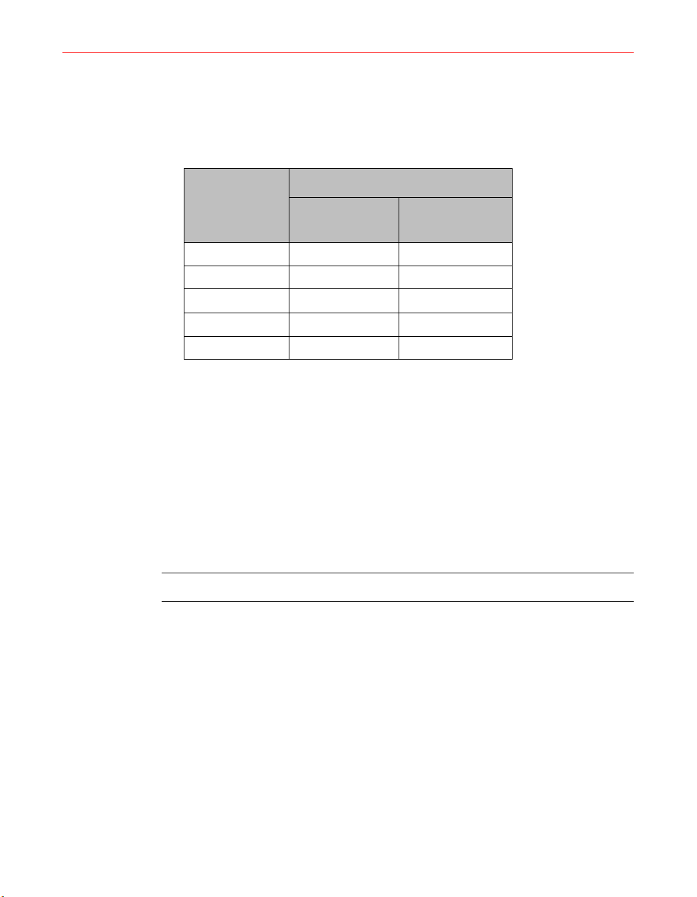
3. Press the LAMP ON switch: the green LAMP ON indicator blinks, then stays lit.
4. Check the line currents. The line currents should conform to the values in Table
11.
Table 11. P300M/P300MQ/P300MT Current Requirements
System Line
Voltage
Single Phase
200 15 14.5
208 14 13.5
220 14 13
230 13.5 13
240 13.5 12
Modular Blower
Line Currents (A)
with K300M
without K300M
Modular Blower
5. Check RF detector and customer use interlocks as described in Chapter 5,
“Troubleshooting.”
Initial Startup Procedure, Multiple-Unit Systems
1. Turn POWER switches of all units to ON.
2. Press the LAMP OFF/RESET switch of the Master.
3. Press the LAMP ON switch of all slaves.
4. Press LAMP ON switch of the Master.
NOTE: Front panel controls take precedence over remote or master commands.
Master/Slave Operation
One master power supply can control up to five slave units. Review Chapter 2,
“Mechanical Installation” to understand the interconnections and programming
needed.
Operating the System
1. Turn POWER switches of all units to ON.
2. Press the LAMP OFF/RESET switch of the Master.
3. Press the LAMP ON switch of all slaves.
Installation, Operation, and Maintenance Manual # 509252 Rev R 57

4. The LAMP CONTROL switches on the Master may now be used to activate all
units in the system at the same time.
NOTE: LAMP CONTROL flashers of slaves will follow LAMP CONTROL on
Master.
Resetting the System After a Fault
If a fault occurs in the system, press the LAMP OFF/RESET switch on the Master, or
cycle the remote LAMP OFF/RESET switch, then press the Master LAMP ON switch
to reset the system.
58 F300S/F300SQ Ultraviolet Lamp System
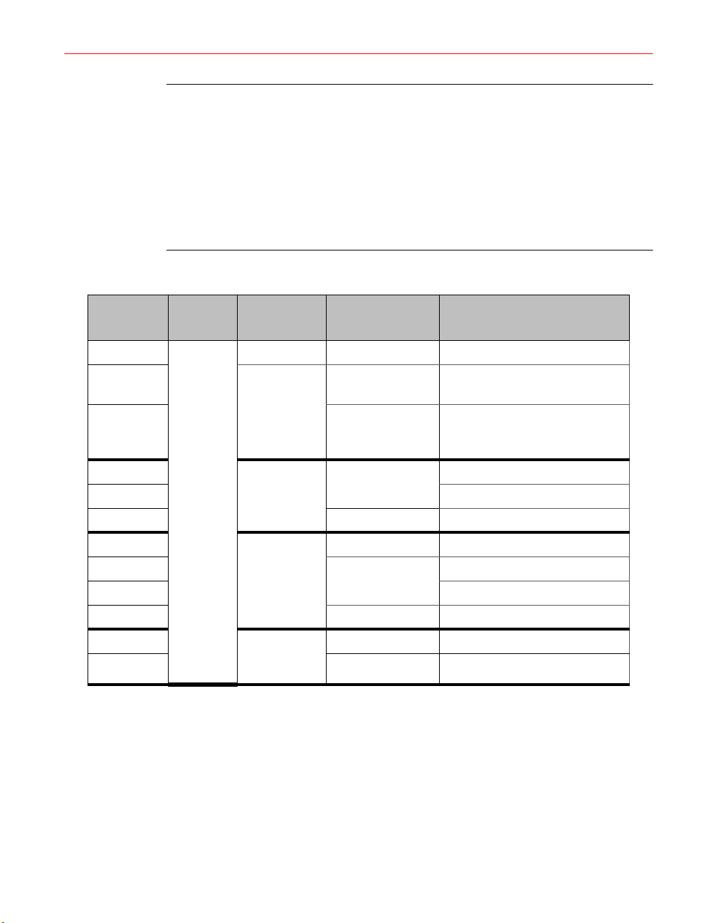
NOTE: Times indicated are approximate and will vary. The exact interval is
determined by conditions within the system.
If additional RF detectors are connected to slaves, an RF fault in one of these
slaves will automatically be interpreted as a system fault shutting down the entire
system.
In a Master/Slave system, the Slave units must be switched to STANDBY or ON
before Master power supply is switched from OFF to STANDBY.
Table 12. Routine Operation
Time
0 sec
1-2 sec
10 sec Steady yellow Interlocks and fault detection
0 sec Lamp On
2-8 sec UV bulb ignites
8-10 sec Steady green UV bulb at full power
0 sec
10 sec
12-18 sec UV bulb ignites
18-20 sec Steady green Full power
0 sec From LAMP
18 sec Steady yellow Ready to restart
Power
Switch
ON
Lamp
Control
Lamp Off Red Control card energized
Standby
from
Standby
From LAMP
OFF to
LAMP ON
ON to
STANDBY
Lamp Control
Flasher
Yellow flash Power supply FAN ON;
Modular Blower ON
circuits function. Ready to
start.
Green flash Start HV transformers
Slow flash yellow
Fast flash green
Yellow flash UV bulb extinguished
Operation
Remote Operation
The F300S/F300SQ can be operated remotely with a STANDBY/LAMP ON switch
connected to the Master. Refer to Chapter 3, “Electrical System” for instructions on
connecting remote switches.
The following procedure describes how to operate a lamp remotely:
1. Turn all remote switches OFF (open contacts).
Installation, Operation, and Maintenance Manual # 509252 Rev R 59

2. Turn the Master POWER switch ON and press the LAMP ON switch.
3. The system will now operate from remote switches. Remote switch functions are
virtually the same as front panel switch functions.
Table 13. Remote Switch Functions
Remote Switch
Lamp ON Lamp ON Standby Lamp ON
Lamp RESET LAMP OFF/RESET Default to lowest state LAMP OFF/RESET
Equivalent Panel
Control
Switch Open Switch Closed
Lamp Status
Operation with Remote Controls
Table 14. Operation with Remote Controls
Panel Controls on Master
Power Lamp Control Lamp ON Lamp Status
Off/Reset S S Off/Reset
ON LAMP OFF/RESET S LAMP OFF/RESET
ON Remote RESET
ON
STANDBY
ON
ON OPEN
Remote
Switches
LAMP OFF/RESET
Switch CLOSED
OPEN
CLOSED
CLOSED Lamp ON
(overrides remote Lamp
ON switch)
STANDBY
KEY:
S- Switch position does not matter.
Quick Restart Option (QRO)
The Quick Restart Option (QRO) provides the ability to restart the lamp at any time,
even immediately after the lamp has been switched to Standby mode. Thus, the
mandatory 18-second restart cycle time associated with routine operation has been
eliminated. The QRO may be installed at the time of the P300MQ power supply
construction or may be retrofitted into P300M power supplies in the field by trained
personnel.
60 F300S/F300SQ Ultraviolet Lamp System

The QRO consists of a high-voltage, low-current power supply section located in the
P300MQ power supply that allows the magnetron in the irradiator to maintain an
ignited bulb at a very low input power level (approximately 10%) and a very low UV
output level (less than 1%). This feature is intended for use in processes that require
occasional periods of decreased UV output, or in the event of a short duration process
interruption.
CAUTION: The QRO is not intended for use
as a shutter, or in processes that require rapid
On-Off cycles. This kind of use may be
detrimental to bulb life span
.
The actual restart time of the bulb will depend upon the elapsed time from when the
lamp was switched from the Lamp On state to the Standby state. Representative data
for the restart time from the QRO state to the Lamp On state (70%, 80%, and 90% UV
output) is shown versus QRO state duration in Figure 16, Figure 17, and Figure 18.
The QRO state, when enabled, will automatically occur when the power supply is
switched from the Lamp On state to the Standby state. The QRO state is indicated by
the alternate flashing of the green Lamp On and yellow Standby buttons on the front
of the power supply. The QRO state will last for a maximum of 40 seconds, after which
it will revert to the Standby state and the yellow button only will remain on.
WARNING: While the lamp’s light output is low
during the QRO state, both eye and skin protection
should be worn in the event of possible direct or
indirect exposure. Refer to Chapter 1, “Safety” for
detailed information regarding ultraviolet radiation
safety.
Installation, Operation, and Maintenance Manual # 509252 Rev R 61

Figure 16. Restart Time Versus QRO State Duration, D-bulb
Figure 17. Restart Time Versus QRO State Duration, H-bulb
62 F300S/F300SQ Ultraviolet Lamp System

Figure 18. Restart Time Versus QRO State Duration, V-bulb
Electrical Installation and Setup
For a power supply with the QRO components installed and properly connected, the
QRO can be enabled by setting the control card DIP switch S1-6 (marked QRO) to the
YES position. See Chapter 3, “Electrical System” for further programming details.
Operation
The QRO state, when enabled by programming switch S1-6 on the control card, will
be active during every transition from the Lamp On state to the Standby state, whether
the lamp is operated remotely or from the front panel. The Lamp On state may be
reentered by pressing the LAMP ON front panel switch or by remotely switching to
Lamp On. If no other action is taken, the Standby state will become active after a QRO
state duration of 40 seconds. The Reset state may be entered at any time by pressing
the RESET front panel switch or by remotely switching to Reset.
In a multiple-unit configuration, mixing QRO and non-QRO units is unlikely.
However, if power supplies with and without the QRO are mixed, units with the QRO
will operate as described in the preceding paragraph, and the units without the QRO
will operate as described previously for a standard P300M power supply. The Initial
Startup Procedure, Master/Slave Operation, and Remote Operation of power supplies
with the QRO are the same as for standard non-QRO units.
See Appendix E, “Replacement Parts” for the QRO parts list.
Installation, Operation, and Maintenance Manual # 509252 Rev R 63

64 F300S/F300SQ Ultraviolet Lamp System
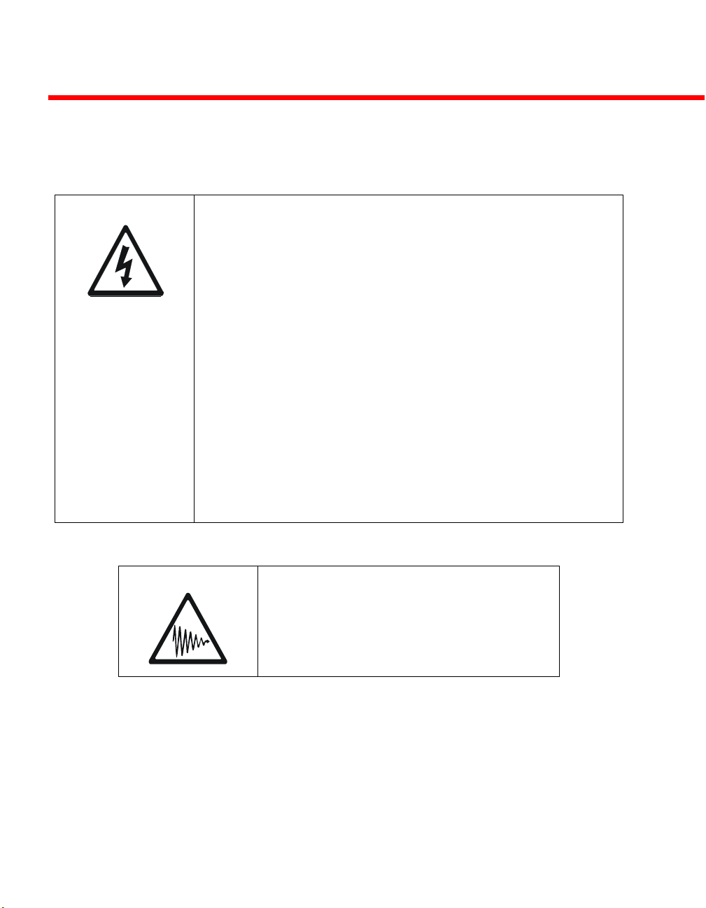
Chapter 5. Troubleshooting
DANGER: High Voltage -- Use extreme caution at all times when
troubleshooting the power supply. Line voltages are present even
when the lamp control switch is set to STANDBY.
Do not measure any voltages not specified in the troubleshooting
procedures: dangerously high voltages exist in the power supply.
Do not touch power supply/irradiator cable connectors while the
system is on. High voltages are present in the connector.
Do not touch any power supply components or wiring while the unit
is operating.
To troubleshoot the power supply, first turn off and disconnect all
power to the unit. All high voltage capacitors have an internal
discharge resistor which should discharge to a safe level in five
seconds. Physically shorting the capacitor terminals with an
insulated screwdriver blade is advised as an additional safety
measure.
Basic Checks
Check that input power is connected properly. Actual line voltage must be within 10%
of the voltage rating shown on the equipment label. Labels are located on the rear of
the power supply. If the input voltage does not match, contact Fusion UV Systems.
DANGER: Ultraviolet Radiation -- Do not
test the irradiator without using adequate
ultraviolet light shielding and never look
directly at the UV lamp. Severe ultraviolet
burning of the skin and eyes can result
without proper safeguards.
Installation, Operation, and Maintenance Manual # 509252 Rev R 65
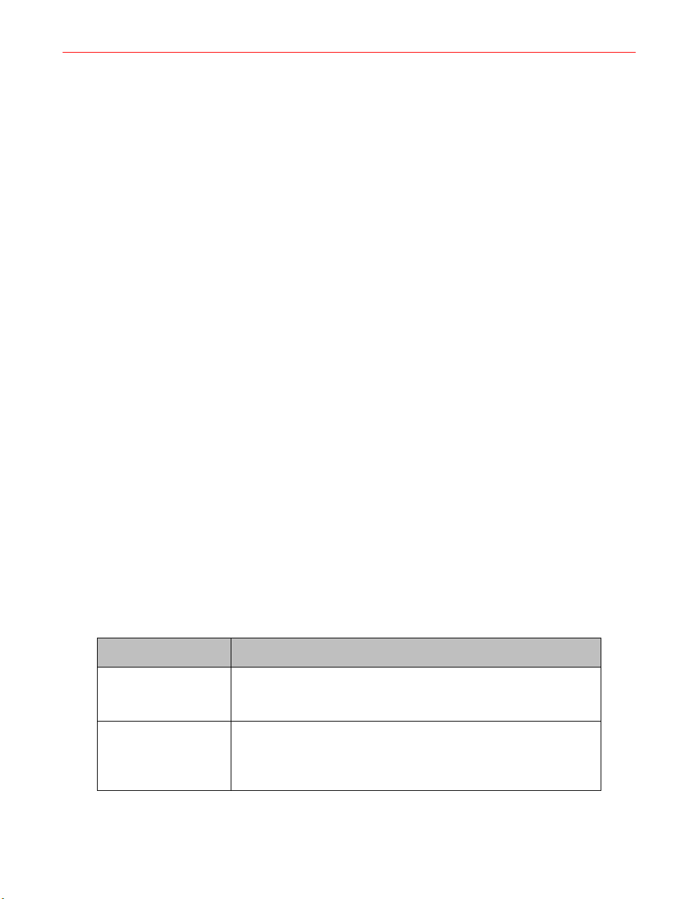
Safety Interlock Tests
The fault indicators, RF detector, and external interlocks should be tested at regular
intervals to assure safe operation of the UV system.
1. With the power supply chassis inserted into the cover and single-phase power
applied, depress the IND TEST button on each power supply. All LED indicators
should light.
2. Turn all POWER control switches to ON. (No UV light is being produced by the
bulb.) Press the STANDBY switches of all units.
3. Operate the external interlock switch(es), by opening light shields, etc. The
system should shut down and produce an LED signal. Reset unit by pressing the
LAMP OFF/RESET switch on the master units.
4. To actuate self-test of the RF detector, depress the test button on the detector and
hold it down for 4 seconds. The system should shut down and produce an RF
Interlock LED signal. Reset as before.
Fault Indicators
When an interlock switch is opened or improper equipment operation is detected, a
fault signal is generated. Power is removed from the irradiator and blower of one or all
units, depending on the type of fault and the programming selected by the user. The
type of fault (Unit or System) is indicated on the front panel of the unit detecting the
fault.
Unit Faults
Unit faults are those detected within an individual module. The Lamp Control switch
and the top five light-emitting diodes on the front panel indicate the unit faults (see
Figure 14 on page 50).
Table 15. Unit Faults
Indicator Description
(HV Cable) If the LAMP OFF/RESET switch is lit when the POWER switch is
ON, but the unit will not go to STANDBY when the switch is
pressed, the high voltage cable is not connected or faulty.
LAMP OUT After ON switch pressed: the photocell was not satisfied within 8
seconds of initial startup time, or the light output fell low enough
to unsatisfy the photocell at any time after startup. After
STANDBY switch: Shorted Photocell detected.
66 F300S/F300SQ Ultraviolet Lamp System
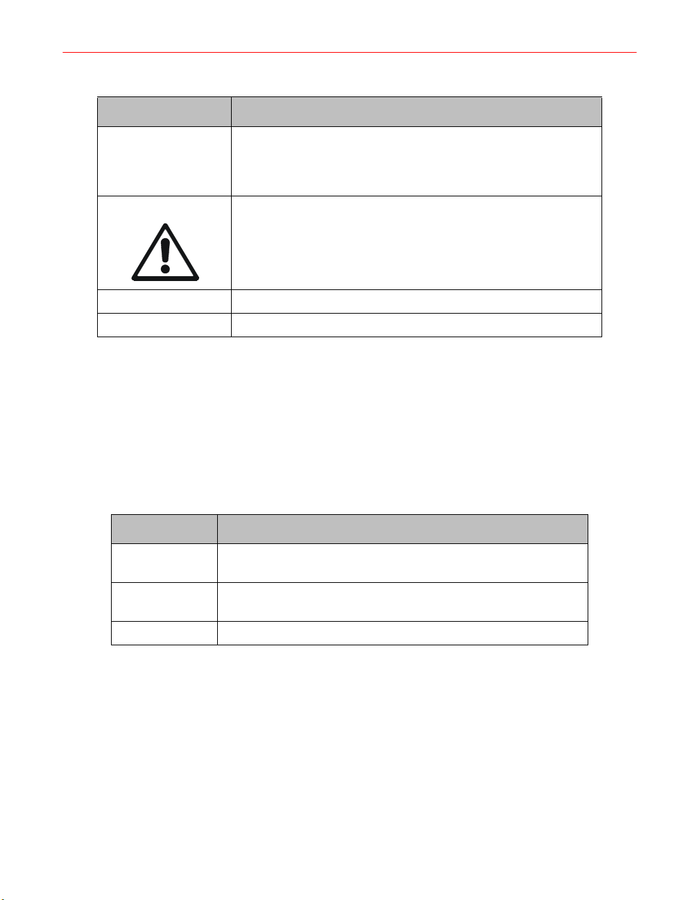
Table 15. Unit Faults (continued)
Indicator Description
PWR ERROR Improper operation of magnetron: either no magnetron anode
current 2-4 seconds after high voltage is applied, or the
presence of high voltage when the Lamp system is in OFF or
STANDBY.
CAUTION: If a PWR ERROR fault is indicated, press the LAMP
OFF/RESET switch immediately. To prevent magnetron
damage, single-phase power should be disconnected (see PWR
ERROR fault).
PS TEMP The power supply is overheating.
BLWR PRESSURE Cooling air pressure within the irradiator is insufficient.
System Faults
The bottom three LEDs indicate system faults. These faults always shut down ALL
units in the system, causing all LAMP CONTROL switches to flash.
System interlock switches and the RF detector may be connected to any unit, but are
normally connected to the master. System faults will then be detected and displayed at
the master power supply.
Indicator Description
SYS BLWR Insufficient cooling air pressure in an external supply or exhaust
blower causes pressure switch to open.
EXT INTLK Open external interlock switch on a plenum cover, for example,
connected at customer option.
RF INTLK Excessive RF at the RF detector, or loss of power to detector.
Fault Diagnosis Tables
To determine the likely cause of failure in an F300S/F300SQ unit, note the operating
sequence when the failure occurs. Also, record which fault indicator LED lights. The
indicator may light immediately when the unit is switched from one condition to
another (for example, from STANDBY to ON); or the signal may be displayed until
after a programmed internal delay has elapsed.
There is a troubleshooting table for each fault indicator, showing secondary symptoms
to help localize the problem. The possible causes are listed, followed by testing and
repair instructions.
Installation, Operation, and Maintenance Manual # 509252 Rev R 67
Table 16. System Faults
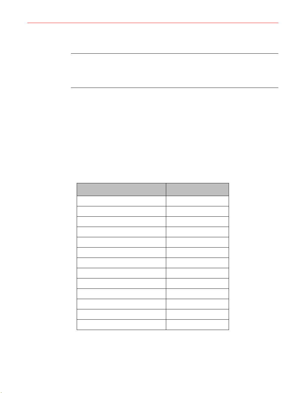
Table 18, “Troubleshooting/Fault Diagnosis,” on page 69 covers miscellaneous faults
and malfunctions.
NOTE: The control card may be responsible for any of the fault conditions
described following. If the fault cannot be determined after investigating all
possible causes listed, check the control card for damage or improperly secured
connectors.
Return malfunctioning control cards to Fusion UV Systems.
Failure Diagnosis Cross-Reference
The F300S/F300SQ system is designed to signal the operator when a failure occurs in
one unit or a multiple unit system. Table 18, “Troubleshooting/Fault Diagnosis,” on
page 69 is organized around these signals and observable clues. Use the following
table to locate the fault indicated.
Notice that the failure of some signals to light is also an indication of a fault.
Table 17. Fault Diagnosis Cross Reference
Signal Page
Arcing sound 81
EXT INTLK 74
LAMP OUT 74, 75, 77, 78, 79, 81
LAMP OUT light is off 77, 78, 79
BLWR PRESSURE 75
PS TEMP 76
PWR IMBAL 75, 80
PWR ERROR 76, 80
LAMP OFF/RESET light is off 73
RF INTLK 73, 75, 80
STANDBY switch does not light 75
SYS BLWR 76
Failure with no signal 73, 75
68 F300S/F300SQ Ultraviolet Lamp System
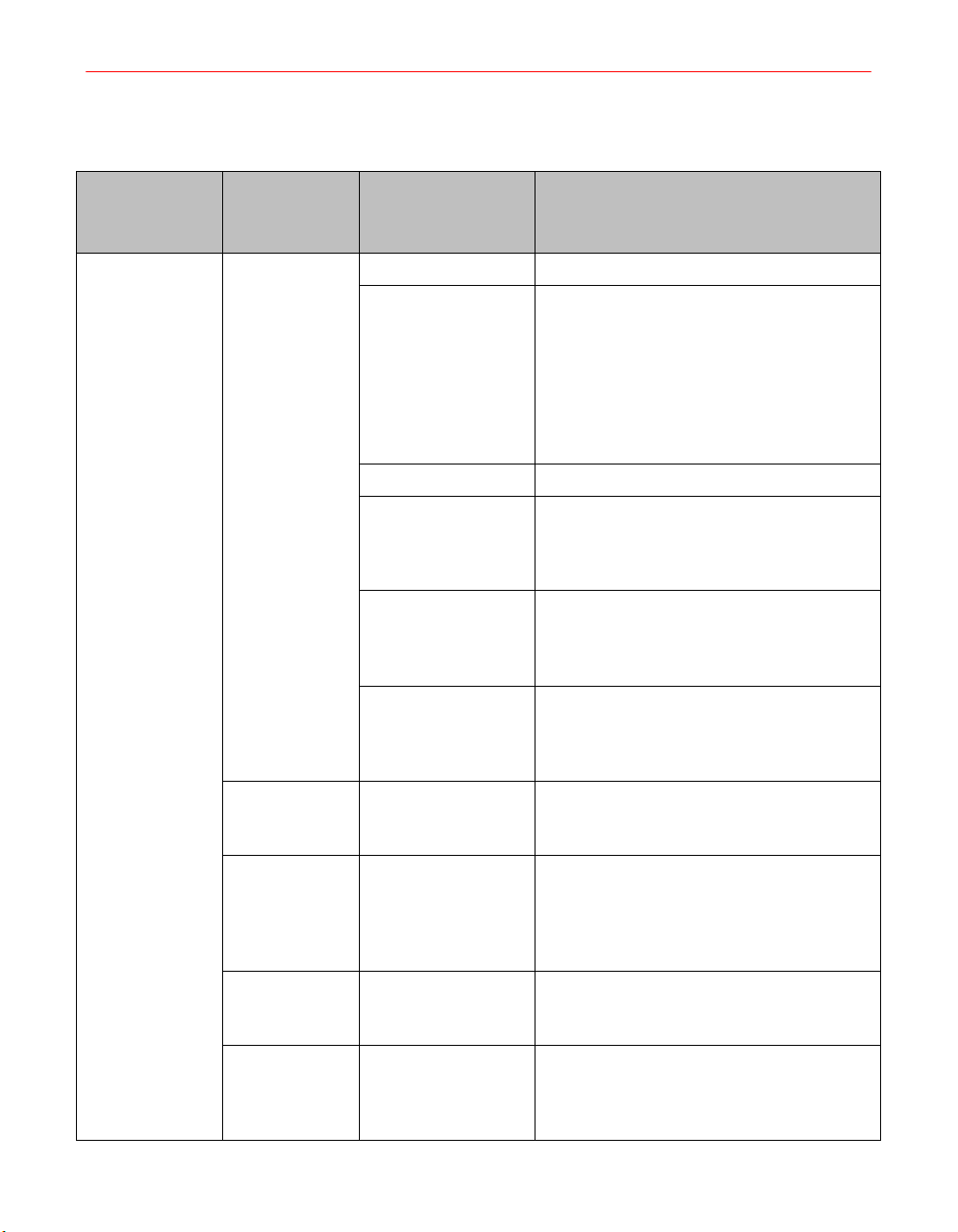
Operation
POWER switch
from OFF to ON
Table 18. Troubleshooting/Fault Diagnosis
Signal/
Other
Symptoms
LAMP
OFF/RESET
button does
not light at
power up
Possible Cause Corrective Action
Fuses F1 and F2 Check fuse and replace if blown.
Power supply wiring If fuse immediately blows again, replace
Control card Replace control card.
Irradiator cable B. Turn OFF. Reconnect P104. Press
RF detector C. Turn OFF. Reconnect P20 at the RF
Filament
transformer
fuses. Then: A. Disconnect P104 on back
of power supply, P10 from the irradiator,
and P20 at the RF detector. Press
STANDBY LAMP CONTROL button. If
fuse does not blow, proceed to (B). If the
fuse blows, the problem is in the internal
wiring or control card.
STANDBY. If the fuse does not blow,
proceed to (C). If the fuse blows, the
problem is in the connectors or cable.
detector. Press STANDBY. If fuse does not
blow, proceed to (D). If the fuse blows, the
problem is in the RF detectors or cable.
D. Turn OFF. Reconnect P10 to the
irradiator. Press STANDBY. If the fuse
blows, the problem is in the filament
transformer or connections.
Master turns
slaves ON but
not OFF
RF INTLK
indicator lights
on slave with
slave OFF,
master ON
RF INTLK
indicator lights
on all units
System shuts
down; no fault
indicators light
Programming error Close S1-1 (YES) on master.
Cable connection Connect cable H760 to slave.
Programming error Close S1-5 (YES) on master.
Momentary loss of ACTurn off all units and then turn each unit
on. A momentary loss of power to one or
more units may be interpreted as a system
fault.
Installation, Operation, and Maintenance Manual # 509252 Rev R 69
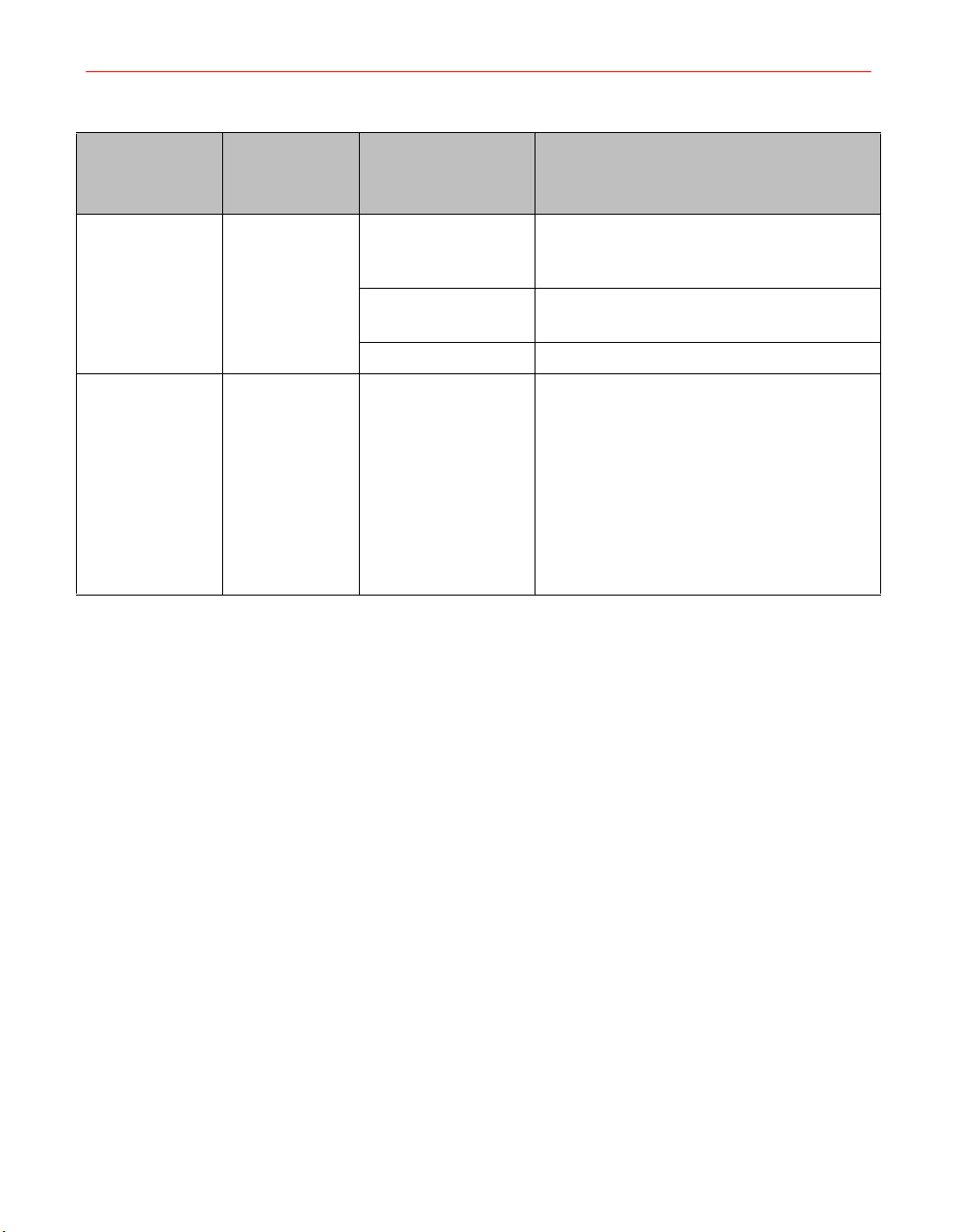
Operation
Lamp control at
OFF, or from
OFF to
STANDBY
Switch from
OFF to
STANDBY or
from LAMP ON
to STANDBY
Table 18. Troubleshooting/Fault Diagnosis (continued)
Signal/
Other
Symptoms
EXT INTLK
indicator lights
LAMP OUT
indicator lights
Possible Cause Corrective Action
Open control input. A jumper or an external circuit between
J105A-9 and J105A-10 must be closed by
a jumper or an external switch.
Poor connection Disconnect all power. Reseat control board
assembly connections. Try again.
Control card Replace the control card.
Shorted photocell Press LAMP OFF switch. Attach voltmeter
probes to Photocell Voltage Test Points.
Press the STANDBY switch. Measure the
photocell voltage between Photocell
Voltage Test Points while in STANDBY.
The voltage level indicated should be
greater than +9.3 VDC. If the voltage level
indicated is less than this value, the
photocell is defective. Replace the
photocell assembly.
70 F300S/F300SQ Ultraviolet Lamp System
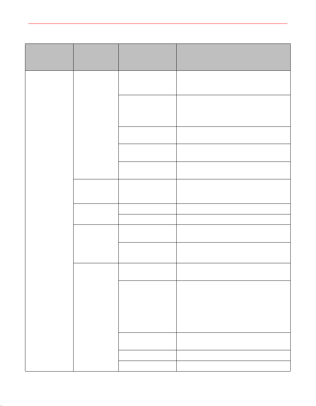
Operation
Table 18. Troubleshooting/Fault Diagnosis (continued)
Signal/
Other
Symptoms
Possible Cause Corrective Action
Switch from
OFF to
STANDBY
BLWR
PRESSURE
indicator lights
STANDBY
switch does
not light
No fault
indicators light.
LAMP OUT
and/or PWR
IMBAL
indicators light
immediately
Single-phase
See “Basic Checks” on page 65.
voltage missing
phase
Air pressure Measure air pressure inside irradiator
following the procedure described in
Chapter 6, “Maintenance”. IF PRESSURE
IS LOW:
Dirty air filters Replace dirty air filter on remote or
modular blower.
Pressure switch
Replace the pressure switch.
faulty
Air handling design Check for adequate air handling
requirements.
HV cable
Connect HV cable.
disconnected
Faulty HV cable Inspect cable, check for continuity.
Control card Replace control card.
Card connectors not
secure
Check control card. All connectors must be
properly secured.
Control card Replace control card.
RF INTLK
indicator lights
or flashes
alternately with
the lamp
control
switches
No RF detector
connected
Programming error:
1. All units have
Connect RF detector. A system must have
at least one RF detector connected.
1. Close S1-5 on unit with RF detector
connected.
S1-5 open.
2. Unit(s) with S1-5
2. Install jumper.
open and no jumper
between J105A-3
and J105A-4.
RF cable shorted or
Check cable for continuity.
open
RF detector faulty Replace RF detector.
Control card Replace control card.
Installation, Operation, and Maintenance Manual # 509252 Rev R 71
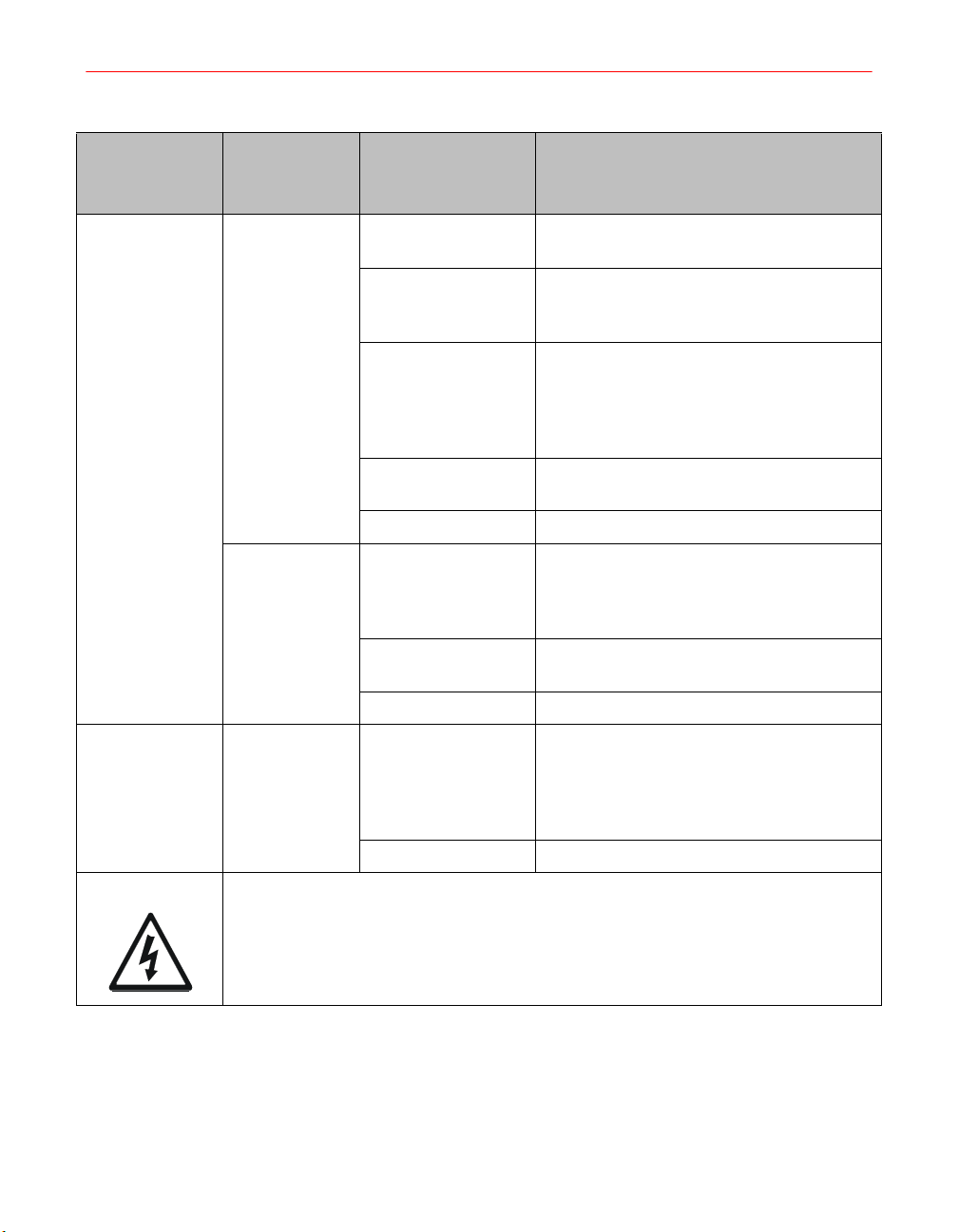
Operation
Table 18. Troubleshooting/Fault Diagnosis (continued)
Signal/
Other
Symptoms
Possible Cause Corrective Action
Switch from
OFF to
STANDBY or
from STANDBY
to ON
Lamp Control at
STANDBY
PS TEMP
indicator lights
SYS BLWR
indicator lights
PWR ERROR
indicator lights
Power supply fan
Repair or replace fan.
inoperative
Power supply too
Move to cooler location.
hot or in poor
location
Temperature switch
faulty or not
connected.
With power off, check the T101 and T102
thermal switches, which should be closed,
with an ohmmeter or DVM. Check that the
thermal switch interconnections are
secure.
Card connectors not
Reseat connectors.
secure
Control card Replace control card.
Blower power;
pressure
If SYS BLWR input for external blower in
J105A is in use, check external blower
power and pressure in the same manner
as remote blower.
Jumper in J105A If SYS BLWR input not in use, check
jumper is in place in connector J105A.
Control card Replace control card.
K101 Check for presence of magnetron current.
If within specifications, then examine
relays for stuck armature or contacts
welded shut. Check operation of relay with
single-phase power only connected.
Control card Replace control card.
CAUTION: Disconnect single-phase power at main circuit breaker immediately.
Magnetron may be severely damaged by application of high voltage when lamp
control is in OFF or STANDBY.
72 F300S/F300SQ Ultraviolet Lamp System
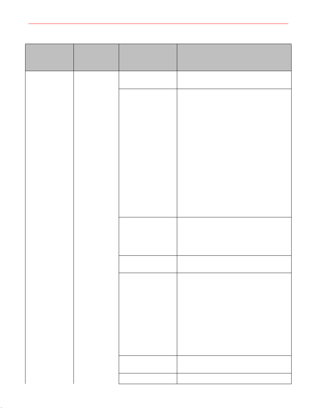
Operation
Switch from
STANDBY to
ON
Table 18. Troubleshooting/Fault Diagnosis (continued)
Signal/
Other
Symptoms
LAMP OUT
indicator lights
after 8
seconds;
Lamp bulb
does not light
Possible Cause Corrective Action
High Voltage Cable Check cable connections at J103, J104,
J10, and J11.
Lamp Bulb Measure the Photoresistor output at the
photocell test points and magnetron
current test points on the front panel while
switching to LAMP ON.
If the photocell voltage does not drop when
the magnetron current voltage changes,
replace the bulb.
If the photocell voltage drops, remove and
inspect the bulb for normal mercury
condensation. If normal mercury
condensation is not observed, (if all the
pellets are at one end, or at the center of
the bulb), if possible, test the bulb in a
separate unit. If the bulb starts, check your
process (air handling, duty cycle, etc.). If
the bulb does not start, replace the bulb.
New bulb During its first start, a new lamp bulb may
take up to 8 seconds after ignition before
reaching full intensity if the mercury (Hg) fill
has accumulated at one end or at the
center of the tube.
High Voltage cable Check cable connections at J103, J104,
J10, and J11.
Control Listen for the sound of K101, the high
voltage contactor, inside the power supply.
It should be heard closing with an audible
click when switched ON (after a three
second wait in STANDBY). If not detected:
Disconnect single-phase power. Reseat
control board assembly connectors P8 and
P9. Observe K1 and K102 when switching
to STANDBY. Reconnect the single-phase
power and observe K2 and K101 when
switching to ON.
K1, K2 Relays Replace K1 and K2 on the control board
assembly.
Control card Replace control card.
Installation, Operation, and Maintenance Manual # 509252 Rev R 73

Operation
Table 18. Troubleshooting/Fault Diagnosis (continued)
Signal/
Other
Symptoms
Possible Cause Corrective Action
Switch from
STANDBY to
ON
(continued)
LAMP OUT
indicator lights
after 8
seconds;
Lamp bulb
does not light
(continued)
Diodes, capacitors If the readings are not different, a power
supply fault is indicated. Disconnect all
power and inspect for wiring damage. Test
diodes and capacitors according to the
procedures in Chapter 6, “Maintenance”.
Irradiator Disconnect all power. Remove the
irradiator cover (see Chapter 6,
“Maintenance”). Inspect for obvious
damage to wiring. Inspect the reflector for
pitting near the large slots, which is
evidence of arcing.
Magnetron If no power supply fault can be found,
disconnect all power. Replace magnetron
(see Chapter 6, “Maintenance”).
WARNING: If no magnetron test voltage is measured at the magnetron test points,
remove power from the unit immediately. Consult Fusion UV Systems Technical
Services.
74 F300S/F300SQ Ultraviolet Lamp System

Operation
Table 18. Troubleshooting/Fault Diagnosis (continued)
Signal/
Other
Symptoms
Possible Cause Corrective Action
Dirty surface Inspect lamp bulb and reflector. Clean or
replace as necessary. Try to start again.
Switch from
STANDBY to
ON (continued)
LAMP OUT
indicator lights
after 8
seconds;
Lamp Bulb
does not light
(continued)
LAMP OUT
indicator lights
after 8
seconds;
UV bulb
reaches full
intensity
Line voltages out of
specification
NOTE: If the magnetron needs to be
replaced prematurely, check that the
single-phase voltage is within specification
(see “Basic Checks” on page 65).
Weak magnetron If photoresistor reading does not fall to
below 9.3 VDC in 8 seconds, a weak
magnetron is commonly indicated.
Photoresistor Measure photoresistor output at Photocell
Voltage Test Points while switching to ON
(see schematic) +12 VDC at STANDBY,
2-5.5 VDC at ON. If voltages are incorrect,
remove the irradiator cover and replace the
photoresistor as described in Chapter 6,
“Maintenance”.
Weak magnetron If photoresistor reading does not fall to
below 9.3 VDC in 8 seconds, a weak
magnetron is commonly indicated.
Connections Disconnect all power. Remove the power
supply cover. Reseat the control card
connectors P6 and P10. Restart.
Control card Replace the control card.
Installation, Operation, and Maintenance Manual # 509252 Rev R 75

Operation
Table 18. Troubleshooting/Fault Diagnosis (continued)
Signal/
Other
Symptoms
Possible Cause Corrective Action
Switch from
STANDBY to
ON
(continued)
PWR IMBAL
indicator lights
PWR ERROR
indicator lights
Power Supply Usually, a diode or capacitor failure will
reduce magnetron current by one-half.
Test the diodes and capacitors according
to Chapter 6, “Maintenance”. The voltage
to the primary coils ONLY of the high
voltage transformers should also be
checked.
Filament
Transformer
Check the filament transformer and
connections.
Control Card Replace the control card if no power
supply, magnetron, or other malfunctions
are found.
Failing (Moding)
Magnetron
Check magnetron current at front panel
test points. If it is not within specifications,
replace magnetron.
Filament
transformer
Check filament transformer and
connections.
Magnetron Check for presence of magnetron current.
If it is zero, disconnect all power, and
replace magnetron. If magnetron current is
low or half, check diode block and HV
capacitors.
Control Card Replace the control card.
RF INTLK
indicator lights
Lamp bulb faulty Replace the lamp bulb.
RF Screen
damaged
RF - arcs forming Inspect reflector for pitting; replace if
RF Detector faulty See “RF Detector” on page 20 to test RF
Position Reposition the detector farther from the
WARNING: The RF detector should at all times be closer to the screen or light shield
opening than personnel working nearby. It should be aimed so that it intercepts RF
radiation from the irradiators.
76 F300S/F300SQ Ultraviolet Lamp System
Replace the RF screen.
necessary.
detectors.
screen and/or the light shield opening.

Operation
Table 18. Troubleshooting/Fault Diagnosis (continued)
Signal/
Other
Symptoms
Possible Cause Corrective Action
Lamp Control at
LAMP ON
LAMP OUT
indicator does
not light, or UV
lamp does not
light
Arcing sound
from irradiator,
a grinding
noise
System not
responding in
accordance
with
programming
switch SW1
settings
Control card Replace control card.
Damaged Reflector Disconnect all power. Inspect reflector for
pitting near large slots. Replace reflector if
necessary.
Wiring or connector Remove irradiator cover and inspect wiring
for damage.
Magnetron Replace the magnetron; see Chapter 6,
“Maintenance”.
Incorrect
See Chapter 3, “Electrical System”.
MASTER/SLAVE
arrangement or
cable hook up
Installation, Operation, and Maintenance Manual # 509252 Rev R 77

78 F300S/F300SQ Ultraviolet Lamp System

Chapter 6. Maintenance
This chapter provides maintenance procedures for the I300M irradiator, the
I310M/311M Irradiator, the P300MT power supply, and the K300 modular blower.
I300M Irradiator
Bulb, Screen, and Reflector Maintenance
Cleaning Guidelines
At least every 500 hours of operation, the irradiator should be removed from the light
shield, and the screen, lamp bulb, and reflector inspected carefully. Clean as needed.
Instructions for removing and replacing these components appear later in this chapter.
Guidelines for cleaning these components follow.
If the reflector or bulb surfaces show signs of dirt, oil, or vaporized materials, they
should be removed and cleaned with a good industrial cleaner, using a lint-free cloth
or tissue. The cleaner should contain no waxes, silicones, dyes or perfumes. Simple
Green® and Windex® are recommended. Wipe away any residues, using the cloth or
tissue with pure water. Alcohol, isopropyl, or methanol may be used for final removal
of residues, except when alcohol is not allowed as a solvent.
If deposits on the screen, bulb, and reflector are consistently found at 500-hour
inspections, the blower filters should be changed more frequently, or a more efficient
filter should be used. These deposits can cause premature failures when particles burn
into the quartz lamp or result in dulling of the reflectors.
Bulb Cleaning
Handle bulbs with a lint-free cloth or tissue taking care not to leave fingerprints.
Baked-on material can be removed from bulbs with a MILD abrasive cleaner such as
Soft Scrub®, followed by a thorough rinse with water. If alcohol is allowed, do a final
wipe with alcohol. Harsh abrasives and steel wool should NEVER be used on bulbs.
Reflector Cleaning
If the reflector surface is dull or discolored, it should be cleaned. Abrasives should
never be used on reflectors.
Installation, Operation, and Maintenance Manual # 509252 Rev R 79
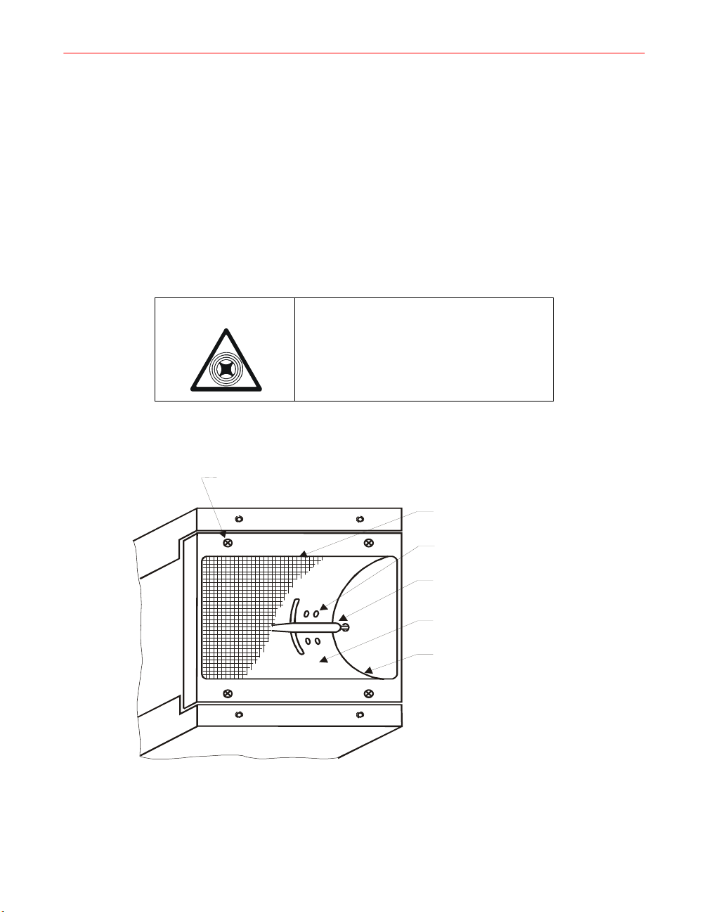
If cleaning reflectors while assembled in the irradiator, drying with compressed air is
NOT recommended because particles or residues can be driven into spaces between
components and into optical sensing elements.
Screen Cleaning
Screens may be cleaned with the same cleaners cited previously, soaking if necessary,
brushing lightly and rinsing well. Take care not to damage the gaskets or the fine
screen wires.
I300M Screen Assembly Removal/Replacement
CAUTION: In handling the irradiator or
screen assembly, try to avoid all direct
contact with the screen, as it punctures
easily. Do not apply pressure to the screen.
M3 screen retaining
screws (4) (2 per side)
Figure 19. Reflector Assembly (I300M)
80 F300S/F300SQ Ultraviolet Lamp System
RF screen
Cooling air holes
Lamp bulb
Cavity
Reflector
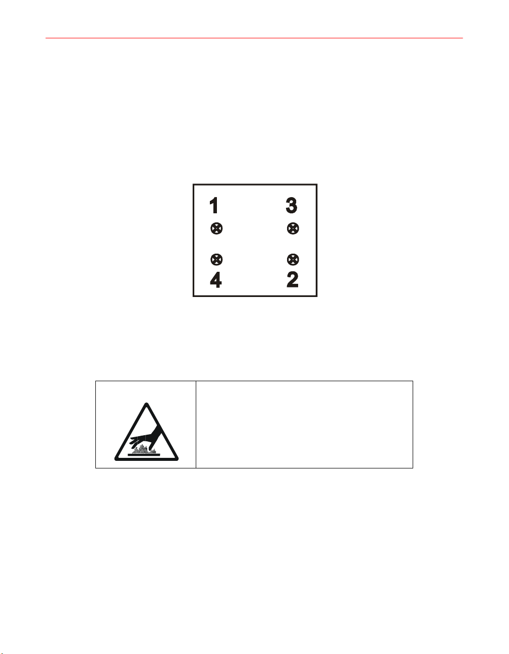
1. Refer to Figure 19. Loosen the four M3 screen retaining screws three turns each.
Repeat, this time removing screws. Grasp the screen frame by both ends, taking
care not to twist or bend the screen itself, and remove screen assembly.
2. To replace existing screen or install a new one, place the screen assembly in
position.
3. Apply pressure to the frame only and press firmly into place. Install the four
screws alternately, working from side to side. Tighten each to a snug position;
finally tighten to 0.9 N-m (8 inch-lbs.) using a torque-controlled screwdriver.
Figure 20. RF Screen Screw Tightening Sequence
Lamp Bulb Removal/Replacement
WARNING: During operation, the lamb bulb
and adjacent metal surfaces become very hot.
Operate the blower for about one minute to
cool hot surfaces.
1. Remove the screen as described in “I300M Screen Assembly
Removal/Replacement” on page 80.
2. Next, see Figure 21 on page 82. Using clean cotton gloves or lint free tissue, grasp
the lamp bulb at one end between the thumb and fingers and apply firm pressure
axially toward the opposite end. When the tip of the bulb has cleared its retaining
hole and is free to move past or along the end reflector, gently slide it up and out.
Installation, Operation, and Maintenance Manual # 509252 Rev R 81
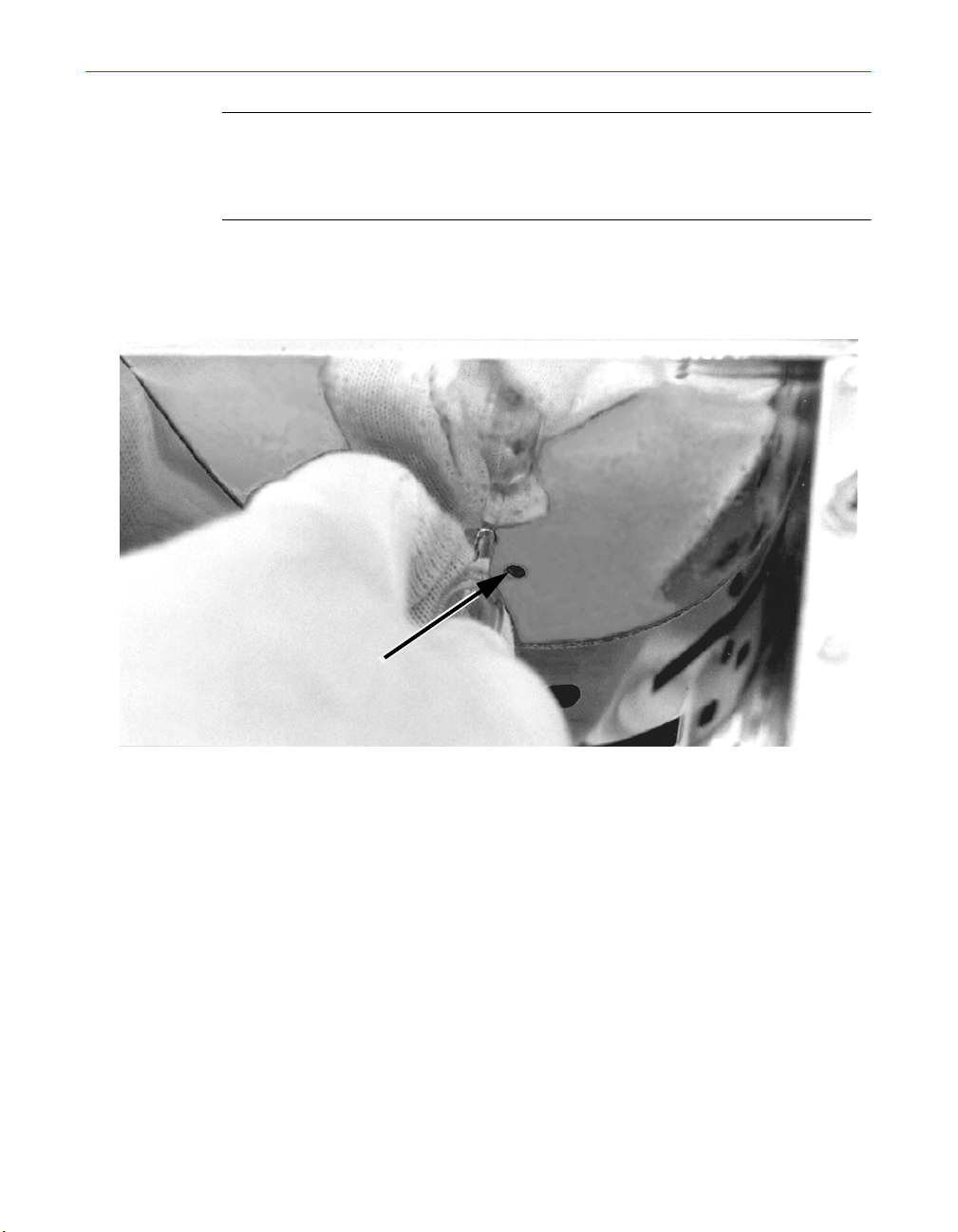
CAUTION: Do not apply bending force to the lamp bulb. Do not touch
the bulb with bare fingers or allow it to contact dirty or greasy surfaces.
Contaminants can be burned into the quartz envelope, causing
premature bulb failure.
3. Clean any deposits from the surface of the bulb (see “Cleaning Guidelines” on page
79).
Retaining hole
Figure 21. Removing or Replacing the Bulb
4. To replace a lamp bulb in the reflector, hold it near the middle and insert the tip
of the bulb into the retaining hole of one end reflector. Apply pressure in the
direction of the length of the bulb, moving it toward the end that is inserted. This
will allow the free end to clear the end reflector. Gently slide the end of the bulb
down to the retaining hole and allow it to pop into position.
Reflector Removal/Replacement
Replace the reflector only if it becomes dull and its surface cannot be cleaned
successfully, or if severe arcing is apparent (dark or burned spots).
1. Remove the screen assembly and the bulb.
2. Remove the six flat head screws and lift the reflector out.
82 F300S/F300SQ Ultraviolet Lamp System
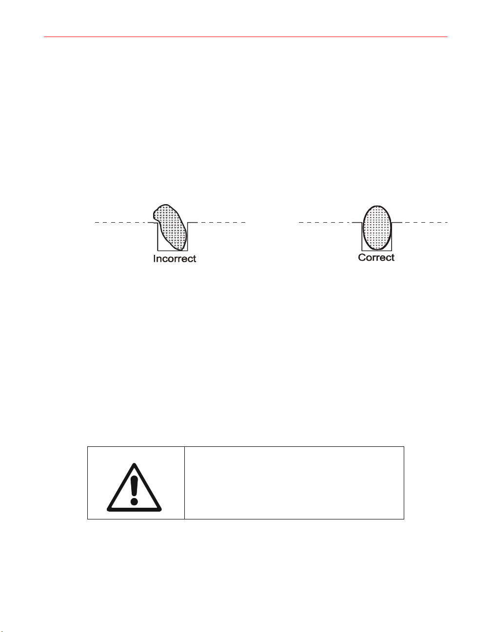
3. Referring to Figure 23, remove and discard the two end reflectors and the gaskets
underneath. If evidence of arcing is present, clean the gasket grooves with emery
cloth to remove all oxide.
4. Insert both end reflectors, ensuring that they both seat fully and evenly. The
replacement end reflectors must be installed before installing the new bulb and
reflectors and the new RF Gasket.
5. Install the two pre-cut (long) RF gaskets into the grooves for the end reflectors.
Insert one end flush with the top of the mounting surfaces (Figure 22). Working
toward the other end of the groove, press the gasket strip down firmly with the
thumbnail so that it rests at the bottom of the groove.
Profile of properly installed gaskets
Figure 22. Gasket Installation
6. Examine the cross-guide gaskets for evidence of arcing. Replace if there is any
evidence of wear or arcing (dark or burned spots). Also if there is evidence of
arcing on the back side of the reflector caused by the cross-guide gaskets (behind
the reflector), then replace them.
Install the two pre-cut RF gaskets (short ones) into the grooves for the
extrusions. Insert one end flush with one edge of the mounting surfaces.
Working toward the other end of the groove, press the gasket strip down firmly
with a thumbnail so that it rests at the bottom of the groove.
IMPORTANT: The dichroic reflector and the R350
reflector do not have plastic protective covers on
the reflector surface. The dichroic reflector has a
dark purple reflective coating. Do not attempt to
remove the purple reflective coating.
Installation, Operation, and Maintenance Manual # 509252 Rev R 83
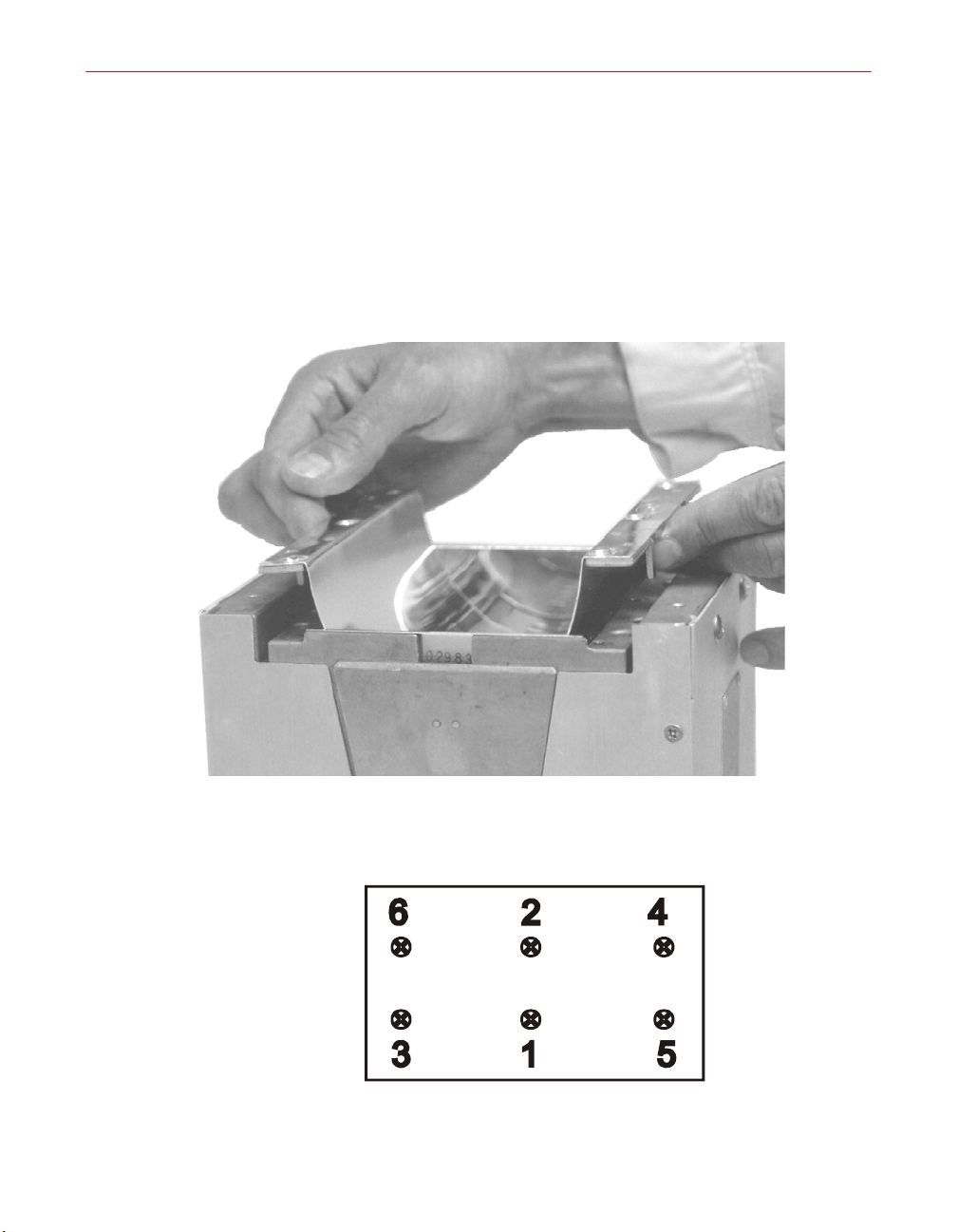
7. Align the reflector squarely over the opening. With gentle pressure and a rocking
motion, slide the reflector down in place. It should not bind against the end
reflectors as it goes into place. As a final motion, grasp the sides of the reflector
and gently force them together a small amount, then settle the reflector down
over the mounting surfaces (Figure 23). Start the six flat head screws in the
reflector but do not tighten. Tighten the six screws in the sequence 1-6 as shown
in Figure 24 to a snug position; finally tighten to 3.4 N-m (30 inch-lbs.) using a
torque controlled screwdriver. Repeat tightening the screws as illustrated and at
the specified torque.
Figure 23. Reflector Removal or Replacement (I300M)
Figure 24. Reflector Screw Tightening Sequence
84 F300S/F300SQ Ultraviolet Lamp System
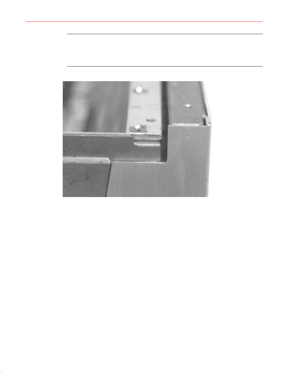
CAUTION: Do not use the flathead screws to pull the reflector into place.
Excessive pull on these screws will deform the reflector face at its bend
radius or loosen its rivets. This would result in a failure of the screen
assembly to seat properly and subsequent damage to the screen gaskets.
Figure 25. Correct Reflector Alignment (I300M)
8. When the reflector is properly installed, the face should be flush and even with
the outer face of the two end reflectors as shown in Figure 25.
9. Clean the reflector to remove fingerprints.
10. Clean and insert the lamp bulb according to “Cleaning Guidelines” on page 79.
Installation, Operation, and Maintenance Manual # 509252 Rev R 85
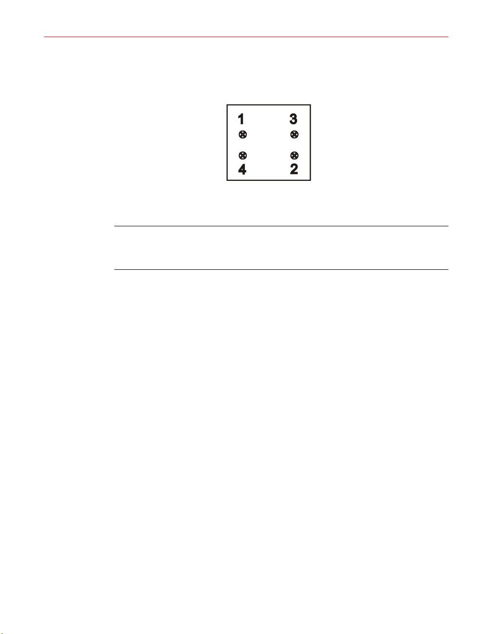
11. Replace the screen assembly. After replacing the screen assembly, refer to
Figure 26; hand-tighten the four M3 screws as shown until snug. Tighten them
in sequence to 0.9 N-m (8 inch-lbs.) using a torque-controlled screwdriver.
Repeat tightening the fasteners according to the sequence and torque specified.
Figure 26. RF Screen Screw Tightening Sequence (I300M)
NOTE: After installing the reflector in the irradiator, the reflector mounting
screws should be retightened (using a torque controlled screwdriver to 3.4 N-m
(30 inch-lbs.)) after a minimum of 10 minutes of operation.
I300M Irradiator Housing Removal/Replacement
The I300M irradiator enclosure is removed as described in the following procedure.
1. Disconnect the cables from J10 and J11.
2. Place the irradiator (screen down) on a clean, level surface.
3. Remove two M3 flat head screws from each side of the irradiator housing.
4. Remove four M5 truss head screws that secure the housing to the casting.
5. Remove two M5 truss head screws that secure the perforated panel to the front
of the irradiator housing.
6. Disconnect the pressure switch tubing from the perforated panel and remove the
panel.
7. Unthread the large plastic nut that secures the J10 connector to the housing and
push the connector into the housing.
8. Lift the housing straight up to remove.
9. Reverse these steps to reassemble.
86 F300S/F300SQ Ultraviolet Lamp System
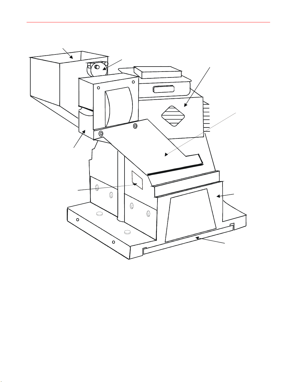
Air intake plenum
Filament transformer
Photo resistor
direct view
assembly
Air pressure switch
Magnetron
Filament
transformer
bracket
Die casting
Figure 27. I300M/I301M Irradiator Component Location
Direct View Photoresistor Removal/Replacement
1. Remove the housing as described in the previous section.
2. Unplug the photoresistor 3-circuit connector (P30) from the photoresistor PWB.
3. Remove the two M4 screws securing the photoresistor mounting block to the
casting and remove the photoresistor assembly.
4. Remove the single screw holding the photoresistor PWB to the mounting block.
Installation, Operation, and Maintenance Manual # 509252 Rev R 87
RF screen
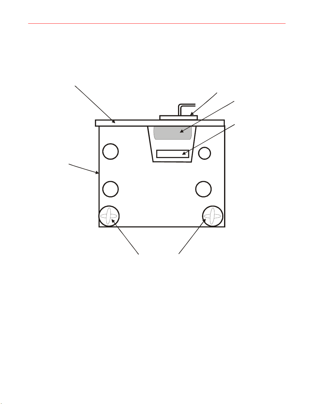
5. Remove and discard the PWB and inspect the UV filter lens for damage.
6. Replace the photoresistor and UV filter lens assembly.
7. Reinstall the housing.
Photoresistor PWB
Photoresistor
mounting
block
Photoresistor mating
connector
Photoresistor
UV filter lens
Photoresistor
block mounting
holes
Figure 28. Photoresistor Assembly for Direct View (I300M)
Filament Transformer Removal/Replacement
1. Remove the irradiator housing.
2. Cut the cable ties and slide the PVC tubing off the magnetron connections.
3. Remove the filament terminal screws. Disconnect the leads at the primary
terminals. Remove the two anchor screws holding the transformer to the side
rail, and remove the transformer.
4. Replace the transformer by reversing the process.
88 F300S/F300SQ Ultraviolet Lamp System
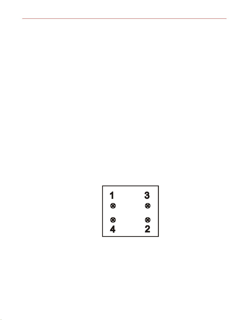
5. Reconnect the filament transformer wires to the magnetron and tighten the
terminal screws to 0.9 N-m (8 inch-lbs) using a torque-limiting screwdriver.
Reposition the tubing over the terminal screws and install cable ties.
6. Install the irradiator housing as described in “I300M Irradiator Housing
Removal/Replacement” on page 86.
Magnetron Removal/Replacement
1. Remove the irradiator housing as described previously.
2. Disconnect filament transformer wires from magnetron by removing the cable
ties and sliding back the tubing. Remove the terminal screws.
3. Remove the filament transformer bracket and air plenum.
4. Remove the four screws fastening the magnetron to the casting. Lift the
magnetron off the waveguide assembly and place it upside down in a clear area
on a wooden bench, at least five inches from any magnetic materials (such as
iron or steel).
5. Install the replacement magnetron and fasten it to the casting using the
associated hardware.
6. Refer to Figure 29; hand tighten the magnetron fasteners in sequence as shown
until snug. Then, tighten the fasteners ¼ turn in sequence. Finally, tighten the
fasteners in sequence to 3.4 N-m (30 inch-lbs) using a torque-controlled driver.
Figure 29. Magnetron Fastener Tightening Sequence (I300M)
7. Install the filament transformer bracket and air plenum.
8. Reconnect the filament transformer wires to the magnetron and tighten the
terminal screws to 0.9 N-m (8 inch-lbs) using a torque-limiting screwdriver.
Reposition the tubing over the terminal screws and install cable ties.
9. Install the irradiator housing as described in “I300M Irradiator Housing
Removal/Replacement” on page 86.
Installation, Operation, and Maintenance Manual # 509252 Rev R 89

Air Pressure Verification
To test air pressure inside the irradiator, remove one cover plate screw and, using a
magnehelic, place the end of the tube over the screw hole (Figure 30 on page 90). For
the I300M, the pressure should be 447-596 Pa (1.8-2.4” H
(ambient) air.
For the I300MB irradiator (modular blower), pressure should be 447 - 822 Pa (1.8 to
3.3” H
2
O).
O) with respect to outside
2
HV Connector (J11)
Cover Plate
Figure 30. Air Pressure Test Points (I300M) - I300 MB Similar
90 F300S/F300SQ Ultraviolet Lamp System
Cover
Screws

Air Pressure Switch Replacement
1. Remove the irradiator cover.
2. Pull the silicone tubing off the low pressure port of the switch.
3. Disconnect the two electrical leads from the switch.
4. Reach inside the air distribution plenum and remove the short length of silicone
tubing which secures the pressure switch to the plenum wall.
5. Insert the high pressure port (longer) of the new switch through the hole in the
plenum wall and secure the switch with a new length of silicone tubing (supplied
with the switch.)
6. Reconnect the electrical leads.
7. Reconnect the low pressure tube to the low pressure port (shorter) on the switch.
8. Reinstall the irradiator cover.
I310M/I311M Irradiator
NOTE: The I310M/I311M model is different from the standard I300M
irradiator in its internal construction, specifically in the reflector assembly and
the RF gaskets used.
Bulb, Screen, and Reflector Maintenance
Cleaning Guidelines
At least every 500 hours of operation, the irradiator should be removed from the light
shield, and the screen, lamp bulb, and reflector inspected carefully. Clean as needed.
Instructions for removing and replacing these components appear later in this chapter.
Guidelines for cleaning these components follow.
If the reflector or bulb surfaces show signs of dirt, oil or vaporized materials, they
should be removed and cleaned with a good industrial cleaner, using a lint-free cloth
or tissue. The cleaner should contain no waxes, silicones, dyes or perfumes. Simple
Green® and Windex® are recommended. Wipe away any residues, using the cloth or
tissue with pure water. Alcohol, isopropyl, or methanol may be used for final removal
of residues, except when alcohol is not allowed as a solvent.
If deposits on the screen, bulb, and reflector are consistently found at 500-hour
inspections, the blower filters should be changed more frequently, or a more efficient
filter should be used. These deposits can cause premature failures when particles burn
into the quartz lamp or cause dulling of the reflectors.
Installation, Operation, and Maintenance Manual # 509252 Rev R 91

Bulb Cleaning
Handle bulbs with a lint-free cloth or tissue taking care not to leave fingerprints.
Baked-on material can be removed from bulbs with a mild abrasive cleaner such as
Soft Scrub®, followed by a thorough rinse with water. If alcohol is allowed, do a final
wipe with alcohol. Harsh abrasives and steel wool should never be used on bulbs.
Reflector Cleaning
If the reflector surface is dull or discolored, it should be cleaned. Abrasives should
never be used on reflectors.
If cleaning reflectors while assembled in the irradiator, drying with compressed air is
not recommended because particles or residues can be driven into spaces between
components and into optical sensing elements.
Screen Cleaning
Screens may be cleaned with the cleaners discussed earlier, soaking if necessary,
brushing lightly, and rinsing well. Take care not to damage the gaskets or the fine
screen wires.
M3 screen retaining
screws (4) (2 per side)
Figure 31. Reflector Assembly (I310M/I311M)
92 F300S/F300SQ Ultraviolet Lamp System
RF screen
Cooling air holes
Lamp bulb
Cavity
Reflector

Screen Assembly Removal/Replacement
CAUTION: In handling the irradiator or
screen assembly, try to avoid all direct
contact with the screen, as it punctures
easily. Do not apply pressure to the screen.
1. Refer to Figure 31. Loosen the four M3 screen retaining screws, using three turns
each. Repeat, this time removing screws. Grasp the screen frame by both ends,
taking care not to twist or bend the screen itself, and remove the screen assembly.
2. To replace an existing screen or install a new one, place the screen assembly in
position.
3. Apply pressure to the frame only and press firmly into place. Install the four
screws alternately, working from side to side. Tighten each to a snug position;
finally tighten to 0.9 N-m (8 inch lbs.) using a torque-controlled screwdriver (see
Figure 37).
Lamp Bulb Removal/Replacement
WARNING: During operation the lamb bulb and
adjacent metal surfaces become very hot. Operate
the blower for about one minute to cool hot
surfaces.
1. Remove the screen as described in “Screen Assembly Removal/Replacement”
on page 93.
2. Refer to Figure 32 on page 94. Using clean cotton gloves or lint free tissue, grasp
the lamp bulb at one end between the thumb and fingers and apply firm pressure
axially toward the opposite end. When the tip of the bulb has cleared its retaining
hole and is free to move past or along the end reflector, gently slide it up and out.
Installation, Operation, and Maintenance Manual # 509252 Rev R 93

CAUTION: Do not apply bending force to lamp bulb. Do not touch the
bulb with bare fingers or allow it to contact dirty or greasy surfaces.
Contaminants can be burned into the quartz envelope, causing
premature bulb failure.
Retaining hole
Figure 32. Removing or Replacing the Bulb (I310M/I311M)
3. Clean any deposits from the surface of the bulb (see “Cleaning Guidelines” on
page 91).
4. To replace a lamp bulb in the reflector, hold it near the middle and insert the tip
of the bulb into the retaining hole of one end reflector. Apply pressure in the
direction of the length of the bulb, moving it toward the end that is inserted. This
will allow the free end to clear the end reflector. Gently slide the end of the bulb
down to the retaining hole and allow it to rest in position.
Reflector Removal/Replacement
Replace the reflector only if it becomes dull and its surface cannot be cleaned
successfully or if severe arcing is apparent.
1. Remove the screen assembly and the bulb.
94 F300S/F300SQ Ultraviolet Lamp System

2. Remove the six flat head screws and lift the reflector out. Examine the
cross-guide gaskets for wear and/or arcing; replace if there is any sign of either.
Replace as described in “Replacing the RF Gasket Assembly” on page 99.
3. Refer to Figure 33 on page 95, and remove and discard the two end reflectors and
the gaskets underneath. If evidence of arcing is present (dark or burned spots),
clean the gasket grooves with emery cloth to remove all oxide.
Figure 33. Reflector Removal or Replacement (I330M/I311M)
Installation, Operation, and Maintenance Manual # 509252 Rev R 95
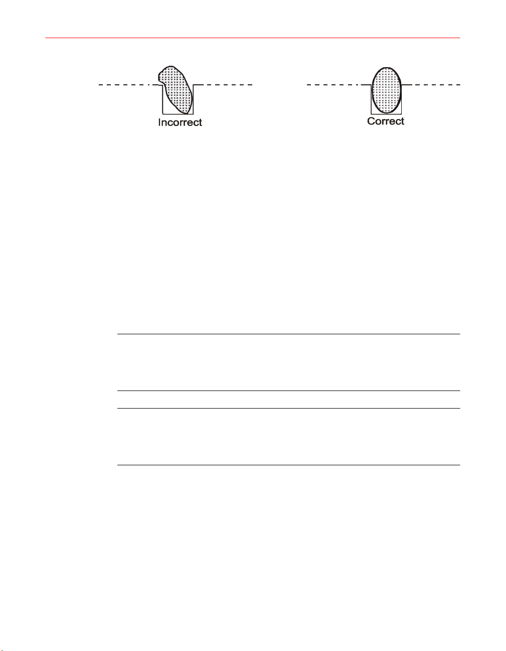
Profile of properly installed gaskets
Figure 34. Gasket Installation (I330M/I311M)
4. Insert both end reflectors, ensuring that they both seat fully and evenly. The
replacement end reflectors must be installed before the new RF Gasket.
5. Install the two pre-cut (long) RF gaskets into the grooves for the end reflectors.
Insert one end flush with the top of the mounting surfaces (Figure 34). Working
toward the other end of the groove, press the gasket strip down firmly with the
thumbnail so that it rests at the bottom of the groove.
6. If you detect evidence of arcing on the back side of the reflector caused by the
RF gasket assemblies behind the reflector, then replace the two RF gasket
assemblies. Replace as described in “Replacing the RF Gasket Assembly” on
page 99.
CAUTION: Do not use the flathead screws to pull the reflector into place.
Excessive pull on these screws will deform the reflector face at its bend
radius or loosen its rivets. This would result in a failure of the screen
assembly to seat properly and subsequent damage to the screen gaskets.
IMPORTANT: The dichroic reflector and the R350 reflector do not have a
plastic protective cover on the reflector surface. The dichroic reflector has
a dark purple reflective coating. Do not attempt to remove the purple
reflective coating.
96 F300S/F300SQ Ultraviolet Lamp System
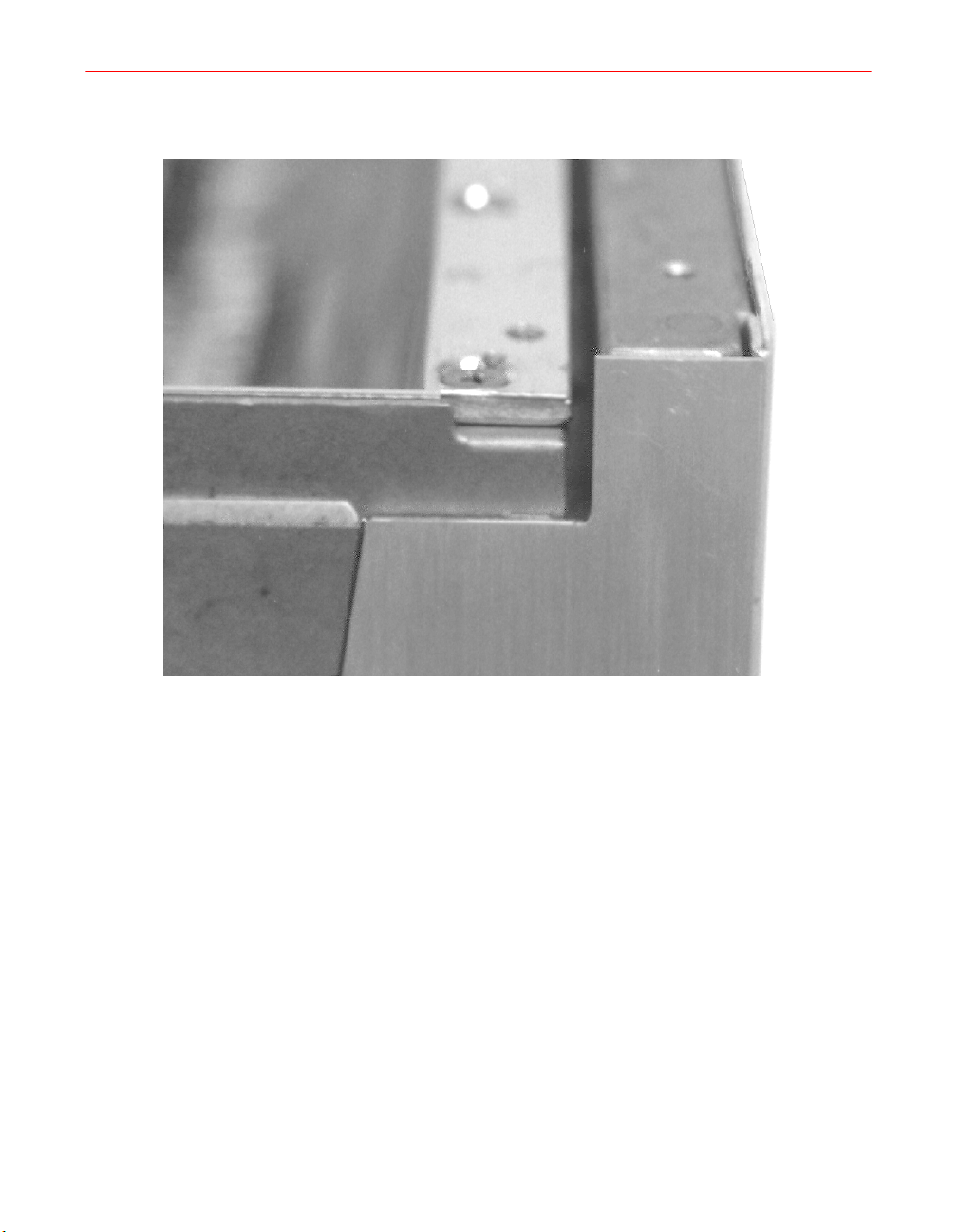
Figure 35. Correct Reflector Alignment (I310M/I311M)
7. Align the reflector squarely over the opening. With gentle pressure and a rocking
motion, slide the reflector down in place. It should not bind against the end
reflectors as it goes into place. As a final motion, grasp the sides of the reflector
and gently force them together a small amount, then settle the reflector down
over the mounting surfaces (Figure 33). Start the six flat head screws in the
reflector but do not tighten. Tighten the six screws in the sequence 1-6 as shown
in Figure 36 to a snug position; finally tighten to 3.4 N-m (30 inch-lbs.) using a
torque-controlled screwdriver. Repeat tightening the screws according to the
illustrated sequence, and at the specified torque.
Installation, Operation, and Maintenance Manual # 509252 Rev R 97
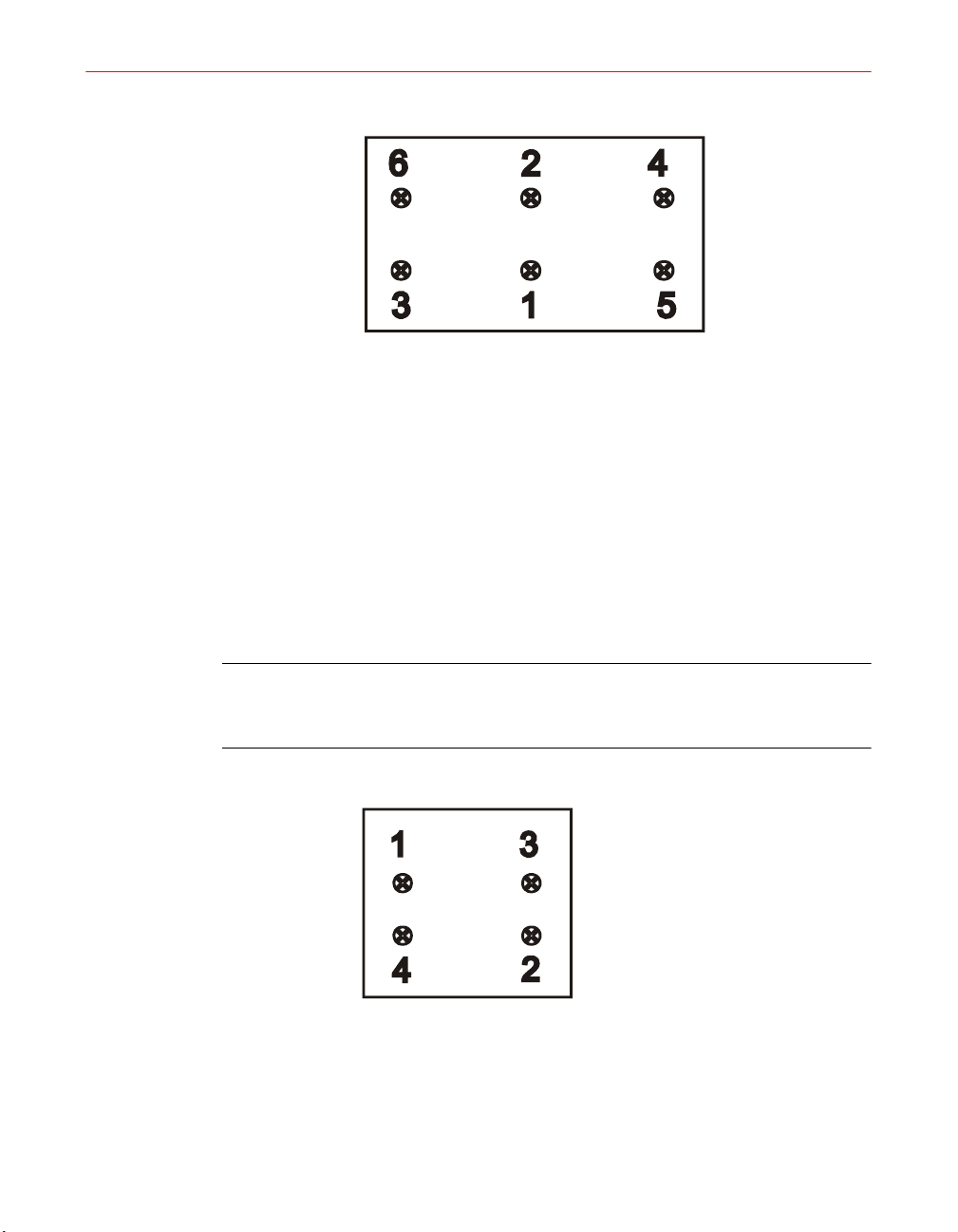
Figure 36. Reflector Screw Tightening Sequence (I310M/I311M)
8. When the reflector is properly installed, the face should be flush and even with
the outer face of the two end reflectors as shown in Figure 35.
9. Clean the reflector to remove fingerprints.
10. Clean and insert the lamp bulb as instructed earlier in this chapter.
11. Replace the screen assembly. Hand-tighten the four M3 screws in sequence as
shown in Figure 37 until snug. Tighten the fasteners in sequence to 0.9 N-m (8
inch-lbs) using a torque-controlled screwdriver. Repeat tightening the fasteners
according to the sequence and torque specified.
NOTE: After installing the reflector in the irradiator, the reflector mounting
screws should be retightened (using a torque-controlled screwdriver to 3.4 N-m
(30 inch-lbs) after a minimum of 10 minutes of operation.
Figure 37. RF Screen Screw Tightening Sequence (I310M/I311M)
98 F300S/F300SQ Ultraviolet Lamp System
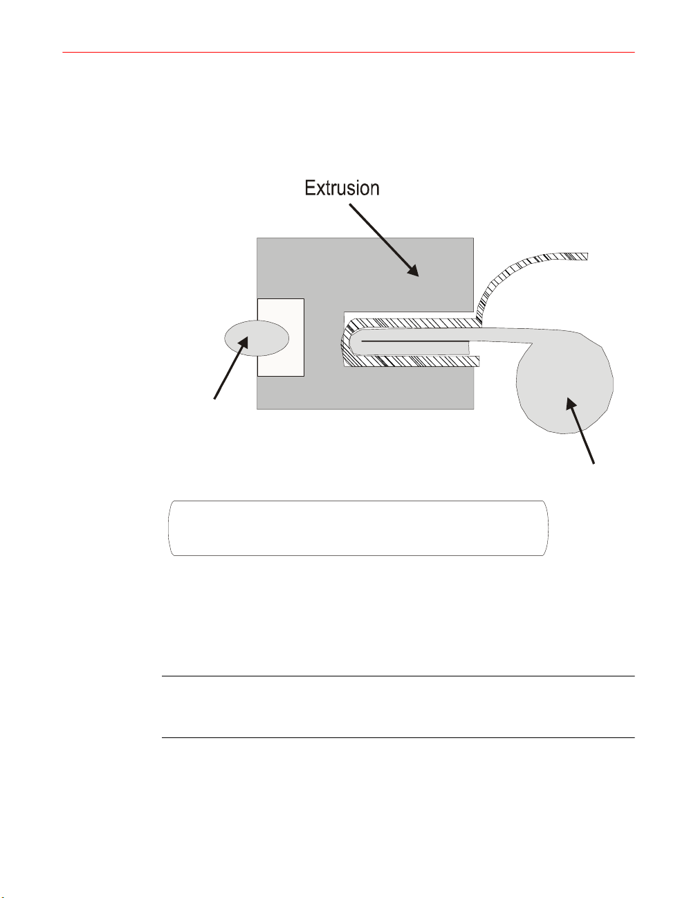
Replacing the RF Gasket Assembly
1. If you detect evidence of arcing on the back of the reflector caused by the RF
gasket assemblies (behind the reflector), then you will need to replace the two
RF gasket assemblies with the main reflector removed.
Cross-guide
(short) Gasket
Mesh
RF SCREEN (Bottom of Irradiator)
Figure 38. Gasket Installation with Cross-guide (Short) Gaskets
(I310M/I311M)
2. Remove the housing (see “I310M/I311M Irradiator Housing
Removal/Replacement” on page 100).
IMPORTANT: The extrusion and the RF gasket assembly are one
assembly, and should not be separated from each other. To replace the RF
gasket requires removal of the old extrusion as well as the old RF gasket.
3. Access the casting by placing the lamp on its side and gently sliding the casting
out of the housing until the eight extrusion screws are accessible. (There are four
screws on each side).
Installation, Operation, and Maintenance Manual # 509252 Rev R 99

4. Remove the extrusions. While holding the extrusion inside the casting, remove
the four screws securing the extrusion to the casting. Repeat for the extrusion on
the opposite side. Discard the old extrusions and the RF gaskets behind each.
5. Install the gasket assemblies (with extrusions) with the mesh facing outward
toward the RF screen (at the bottom of the irradiator) along with the two
cross-guide (short) gaskets behind each assembly. Install the replacement
extrusions using the same mounting screws. The extrusions should be positioned
flush to the casting and as far from the face of the lamp as the mounting screws
allow. Tighten the screws to 2.5 N-m (22 inch-lbs.) using a torque-limiting
screwdriver.
I310M/I311M Irradiator Housing Removal/Replacement
The irradiator enclosure is removed as follows:
1. Disconnect the cables from J10 and J11.
2. Place the irradiator (screen down) on a clean, level surface.
3. Remove two M3 flat head screws from each side of irradiator housing.
4. Remove four M5 truss head screws that secure the housing to the casting.
5. Remove two M5 truss head screws that secure the perforated panel to the front
of the irradiator housing.
6. Disconnect the pressure switch tubing from the perforated panel and remove the
panel.
7. Unthread the large plastic nut that secures the J10 connector to the housing, and
push the connector into the housing.
8. Lift the housing straight up to view the interior components of the irradiator, as
shown in Figure 39 on page 101.
9. Reverse these steps to reassemble.
I310M/I311M Scatter View Photoresistor Removal/Replacement
Figure 39 on page 101 shows the I310M/I311M Irradiator component locations.
1. Remove the irradiator housing.
2. Unsolder the photoresistor lead wires (blue wire next to the diode and a
blue/white wire at the top terminal.)
3. Remove the two M5x10 mm photoresistor fastening screws and remove the
photoresistor assembly.
4. Reverse these steps to replace the photoresistor assembly.
100 F300S/F300SQ Ultraviolet Lamp System
 Loading...