


F300S/F300SQ
Ultraviolet Lamp System
Installation, Operation, and Maintenance
Manual No. 509252 Rev R 3/04
FUSION UV SYSTEMS, INC.
910 Clopper Road
Gaithersburg, MD 20878-1357 USA
(301) 527-2660 • FAX (301) 527-2661

F300S/F300SQ Ultraviolet
Lamp System
Installation, Operation, and Maintenance
Manual No. 509252 Rev R 3/04
Applies to systems using P300M/P300MQ/P300MT power supplies, and I300M/I310M series irradiators Serial Numbers 1001 and later.
(C) Copyright 2004 Fusion UV Systems, Inc. All Rights Reserved.
The products covered herein conform to EC standards.
See Appendix A for details.
FUSION UV SYSTEMS, INC.
910 Clopper Road
Gaithersburg, MD 20878-1357 USA
(301) 527-2660 • FAX (301) 527-2661

Table Of Contents
Introduction . . . . . . . . . . . . . . . . . . . . . . . . . . . . . . . . . . . . . . . . . . . . . . . . . 11
Document Conventions . . . . . . . . . . . . . . . . . . . . . . . . . . . . . . . . |
12 |
Indications of Note, Caution, Warning, and Danger . . . . . . . . . |
12 |
Icon Usage . . . . . . . . . . . . . . . . . . . . . . . . . . . . . . . . . . . . . |
13 |
System Description . . . . . . . . . . . . . . . . . . . . . . . . . . . . . . . . . . |
15 |
System Components . . . . . . . . . . . . . . . . . . . . . . . . . . . . . . . . . |
17 |
Control . . . . . . . . . . . . . . . . . . . . . . . . . . . . . . . . . . . . . . . . |
17 |
Cooling . . . . . . . . . . . . . . . . . . . . . . . . . . . . . . . . . . . . . . . |
18 |
Irradiators . . . . . . . . . . . . . . . . . . . . . . . . . . . . . . . . . . . . . . . . . |
18 |
Reflector and Cavity . . . . . . . . . . . . . . . . . . . . . . . . . . . . . . |
19 |
Lamp Bulb . . . . . . . . . . . . . . . . . . . . . . . . . . . . . . . . . . . . . |
19 |
Mounting . . . . . . . . . . . . . . . . . . . . . . . . . . . . . . . . . . . . . . |
20 |
Power Supply . . . . . . . . . . . . . . . . . . . . . . . . . . . . . . . . . . . . . . |
20 |
P300M/P300MQ/P300MT . . . . . . . . . . . . . . . . . . . . . . . . . . . |
20 |
RF Detector . . . . . . . . . . . . . . . . . . . . . . . . . . . . . . . . . . . . . . . . |
20 |
System Interconnections . . . . . . . . . . . . . . . . . . . . . . . . . . . . . . |
20 |
Warranty Policy . . . . . . . . . . . . . . . . . . . . . . . . . . . . . . . . . . . . . |
21 |
Shipping Instructions . . . . . . . . . . . . . . . . . . . . . . . . . . . . . . . . . |
22 |
Returned Material Authorization Number . . . . . . . . . . . . . . . . |
22 |
General Packing Instructions . . . . . . . . . . . . . . . . . . . . . . . . |
22 |
Power Supply . . . . . . . . . . . . . . . . . . . . . . . . . . . . . . . . |
22 |
Irradiators . . . . . . . . . . . . . . . . . . . . . . . . . . . . . . . . . . . . . |
23 |
Magnetrons . . . . . . . . . . . . . . . . . . . . . . . . . . . . . . . . . . . . |
23 |
UV Bulbs . . . . . . . . . . . . . . . . . . . . . . . . . . . . . . . . . . . . . . |
23 |
Control Cards . . . . . . . . . . . . . . . . . . . . . . . . . . . . . . . . . . . |
23 |
RF Detectors . . . . . . . . . . . . . . . . . . . . . . . . . . . . . . . . . . . . |
23 |
Chapter 1. Safety . . . . . . . . . . . . . . . . . . . . . . . . . . . . . . . . . . . . . . . . . . . . 25
Ultraviolet Radiation . . . . . . . . . . . . . . . . . . . . . . . . . . . . . . . . . . 26
Microwave Radiation . . . . . . . . . . . . . . . . . . . . . . . . . . . . . . . . . . 26
Personnel Effects of Microwave Radiation . . . . . . . . . . . . . . . . . . . 27
Radio Interference . . . . . . . . . . . . . . . . . . . . . . . . . . . . . . . . . . . 27
Ozone . . . . . . . . . . . . . . . . . . . . . . . . . . . . . . . . . . . . . . . . . . . . 28
Installation, Operation, and Maintenance Manual # 509252 Rev R |
5 |

Temperature . . . . . . . . . . . . . . . . . . . . . . . . . . . . . . . . . . . . . . . 28
High Voltage . . . . . . . . . . . . . . . . . . . . . . . . . . . . . . . . . . . . . . . 29
UV Curable Materials . . . . . . . . . . . . . . . . . . . . . . . . . . . . . . . . . 29
Chapter 2. Mechanical Installation . . . . . . . . . . . . . . . . . . . . . . . . . . . . . . 31
Mechanical Installation Checklist . . . . . . . . . . . . . . . . . . . . . . . . . |
31 |
Unpacking and Inspection . . . . . . . . . . . . . . . . . . . . . . . . . . |
31 |
Power Supply Unit(s) Placement . . . . . . . . . . . . . . . . . . . . . . . . . |
32 |
Irradiator Mounting . . . . . . . . . . . . . . . . . . . . . . . . . . . . . . . . . . |
33 |
Lamps Mounted in Opposing Configuration . . . . . . . . . . . . . . . . . . |
34 |
UV Light Shielding . . . . . . . . . . . . . . . . . . . . . . . . . . . . . . . . . . . |
34 |
RF Detector Mounting . . . . . . . . . . . . . . . . . . . . . . . . . . . . . . . . . |
35 |
Remote Blowers . . . . . . . . . . . . . . . . . . . . . . . . . . . . . . . . . . . . . |
36 |
Irradiator Exhaust Venting . . . . . . . . . . . . . . . . . . . . . . . . . . . . . |
36 |
Quartz Plates . . . . . . . . . . . . . . . . . . . . . . . . . . . . . . . . . . . . . . . |
36 |
Chapter 3. Electrical System . . . . . . . . . . . . . . . . . . . . . . . . . . . . . . . . . . . 39
Electrical Installation/Setup Checklist . . . . . . . . . . . . . . . . . . . . . . 39
Accessory Parts List . . . . . . . . . . . . . . . . . . . . . . . . . . . . . . . . . . 39
Interconnect Cables . . . . . . . . . . . . . . . . . . . . . . . . . . . . . . . . . . 40
Connection and Program Log . . . . . . . . . . . . . . . . . . . . . . . . . . . . 40
Installing the External Interlocks Control . . . . . . . . . . . . . . . . 40
User Connections . . . . . . . . . . . . . . . . . . . . . . . . . . . . . . . . 40
Power Supply Programming . . . . . . . . . . . . . . . . . . . . . . . . . . . . . 41
Settings for Six-Position Switch S1 . . . . . . . . . . . . . . . . . . . . 41
Single Unit Programming and Connections . . . . . . . . . . . . . . . . . . 43
Programming . . . . . . . . . . . . . . . . . . . . . . . . . . . . . . . . . . . . . . . 44
Irradiator Cable H340 Connections . . . . . . . . . . . . . . . . . . . . 44
Input/Output Connections . . . . . . . . . . . . . . . . . . . . . . . . . . 45
Remote Inputs . . . . . . . . . . . . . . . . . . . . . . . . . . . . . . . . . . 45
Output Ports (J105B) . . . . . . . . . . . . . . . . . . . . . . . . . . . . . . . . . 46
Alternate Function for K5 . . . . . . . . . . . . . . . . . . . . . . . . . . . 47
Multiple-Unit Programming and Connections . . . . . . . . . . . . . . . . . 48
Programming . . . . . . . . . . . . . . . . . . . . . . . . . . . . . . . . . . . 49
Connections . . . . . . . . . . . . . . . . . . . . . . . . . . . . . . . . . . . . 49
6 F300S/F300SQ Ultraviolet Lamp System

Power Source . . . . . . . . . . . . . . . . . . . . . . . . . . . . . . . . . . . . . . 50 System Power Connections . . . . . . . . . . . . . . . . . . . . . . . . . . 50 Frequency Tapping of HV Capacitors . . . . . . . . . . . . . . . . . . . 51 QRO HV Capacitors (For QRO only) . . . . . . . . . . . . . . . . . . . . 51 High Voltage Transformer Taps . . . . . . . . . . . . . . . . . . . . . . . 51 QRO Transformer Taps (FOR QRO only) . . . . . . . . . . . . . . . . . 52
F300S Relay Coil Resistor Assembly Installation . . . . . . . . . . . . . . 53 Installation Instructions . . . . . . . . . . . . . . . . . . . . . . . . . . . . 53
Chapter 4. Operation . . . . . . . . . . . . . . . . . . . . . . . . . . . . . . . . . . . . . . . . . 55
System Operation Controls . . . . . . . . . . . . . . . . . . . . . . . . . . . . . |
55 |
Lamp Control . . . . . . . . . . . . . . . . . . . . . . . . . . . . . . . . . . . |
55 |
Power . . . . . . . . . . . . . . . . . . . . . . . . . . . . . . . . . . . . . . . . |
56 |
Off/Reset Control . . . . . . . . . . . . . . . . . . . . . . . . . . . . . . . . |
56 |
Initial Startup Procedure, Single Unit . . . . . . . . . . . . . . . . . . . . . . |
56 |
Initial Startup Procedure, Multiple-Unit Systems . . . . . . . . . . . . . . |
57 |
Master/Slave Operation . . . . . . . . . . . . . . . . . . . . . . . . . . . . |
57 |
Operating the System . . . . . . . . . . . . . . . . . . . . . . . . . . . . . |
57 |
Resetting the System After a Fault . . . . . . . . . . . . . . . . . . . . |
58 |
Remote Operation . . . . . . . . . . . . . . . . . . . . . . . . . . . . . . . . . . . |
59 |
Operation with Remote Controls . . . . . . . . . . . . . . . . . . . . . . |
60 |
Quick Restart Option (QRO) . . . . . . . . . . . . . . . . . . . . . . . . . . . . |
60 |
Electrical Installation and Setup . . . . . . . . . . . . . . . . . . . . . . |
63 |
Operation . . . . . . . . . . . . . . . . . . . . . . . . . . . . . . . . . . . . . . |
63 |
Chapter 5. Troubleshooting . . . . . . . . . . . . . . . . . . . . . . . . . . . . . . . . . . . 65
Basic Checks . . . . . . . . . . . . . . . . . . . . . . . . . . . . . . . . . . . . . . . 65
Safety Interlock Tests . . . . . . . . . . . . . . . . . . . . . . . . . . . . . . . . . 66
Fault Indicators . . . . . . . . . . . . . . . . . . . . . . . . . . . . . . . . . . . . . 66
Unit Faults . . . . . . . . . . . . . . . . . . . . . . . . . . . . . . . . . . . . . 66
System Faults . . . . . . . . . . . . . . . . . . . . . . . . . . . . . . . . . . . 67
Fault Diagnosis Tables . . . . . . . . . . . . . . . . . . . . . . . . . . . . . . . . 67
Failure Diagnosis Cross-Reference . . . . . . . . . . . . . . . . . . . . . . . . 68
Chapter 6. Maintenance . . . . . . . . . . . . . . . . . . . . . . . . . . . . . . . . . . . . . . . 79
I300M Irradiator . . . . . . . . . . . . . . . . . . . . . . . . . . . . . . . . . . . . 79
Installation, Operation, and Maintenance Manual # 509252 Rev R |
7 |

Bulb, Screen, and Reflector Maintenance . . . . . . . . . . . . . . . |
. 79 |
Cleaning Guidelines . . . . . . . . . . . . . . . . . . . . . . . . . . |
. 79 |
Bulb Cleaning . . . . . . . . . . . . . . . . . . . . . . . . . . . . . . . . |
79 |
Reflector Cleaning . . . . . . . . . . . . . . . . . . . . . . . . . . . . . |
79 |
Screen Cleaning . . . . . . . . . . . . . . . . . . . . . . . . . . . . . . |
80 |
I300M Screen Assembly Removal/Replacement . . . . . . . . . . . |
80 |
Lamp Bulb Removal/Replacement . . . . . . . . . . . . . . . . . . . . |
81 |
Reflector Removal/Replacement . . . . . . . . . . . . . . . . . . . . . . |
82 |
I300M Irradiator Housing Removal/Replacement . . . . . . . . . . |
86 |
Direct View Photoresistor Removal/Replacement . . . . . . . . . . . |
87 |
Filament Transformer Removal/Replacement . . . . . . . . . . . . . |
88 |
Magnetron Removal/Replacement . . . . . . . . . . . . . . . . . . . . . |
89 |
Air Pressure Verification . . . . . . . . . . . . . . . . . . . . . . . . . . . . |
90 |
Air Pressure Switch Replacement . . . . . . . . . . . . . . . . . . |
91 |
I310M/I311M Irradiator . . . . . . . . . . . . . . . . . . . . . . . . . . . . . . . |
91 |
Bulb, Screen, and Reflector Maintenance . . . . . . . . . . . . . . . . |
91 |
Cleaning Guidelines . . . . . . . . . . . . . . . . . . . . . . . . . . . |
91 |
Bulb Cleaning . . . . . . . . . . . . . . . . . . . . . . . . . . . . . . . . |
92 |
Reflector Cleaning . . . . . . . . . . . . . . . . . . . . . . . . . . . . . |
92 |
Screen Cleaning . . . . . . . . . . . . . . . . . . . . . . . . . . . . . . |
92 |
Screen Assembly Removal/Replacement . . . . . . . . . . . . . . . . |
93 |
Lamp Bulb Removal/Replacement . . . . . . . . . . . . . . . . . . . . |
93 |
Reflector Removal/Replacement . . . . . . . . . . . . . . . . . . . . . . |
94 |
Replacing the RF Gasket Assembly . . . . . . . . . . . . . . . . . |
99 |
I310M/I311M Irradiator Housing Removal/Replacement . . . . . |
100 |
I310M/I311M Scatter View Photoresistor Removal/Replacement . . |
|
100 |
|
Direct View Photoresistor Removal/Replacement . . . . . . . . . . |
101 |
Filament Transformer Removal/Replacement . . . . . . . . . . . . |
103 |
Magnetron Removal/Replacement . . . . . . . . . . . . . . . . . . . . |
104 |
Air Pressure Verification . . . . . . . . . . . . . . . . . . . . . . . . . . . |
105 |
Air Pressure Switch Replacement . . . . . . . . . . . . . . . . . |
105 |
P300M/P300MQ Power Supply . . . . . . . . . . . . . . . . . . . . . . . . . . |
106 |
Safety Procedures . . . . . . . . . . . . . . . . . . . . . . . . . . . . . . . |
106 |
Test Point Voltages . . . . . . . . . . . . . . . . . . . . . . . . . . . . . . |
107 |
8 F300S/F300SQ Ultraviolet Lamp System

Control Card Removal/Replacement . . . . . . . . . . . . . . . 107
Diode Test . . . . . . . . . . . . . . . . . . . . . . . . . . . . . . . . . 108
Capacitor Test . . . . . . . . . . . . . . . . . . . . . . . . . . . . . . 110
High Voltage Transformer Removal/Replacement . . . . . . 110
P300MT Power Supply . . . . . . . . . . . . . . . . . . . . . . . . . . . . . . . 112
Routine Maintenance . . . . . . . . . . . . . . . . . . . . . . . . . . . . . 112
Safety Procedures . . . . . . . . . . . . . . . . . . . . . . . . . . . . 112
Test Point Voltages. . . . . . . . . . . . . . . . . . . . . . . . . . . . . . . 113
Control Card Removal/Replacement . . . . . . . . . . . . . . . . . . . 113
Diode Test . . . . . . . . . . . . . . . . . . . . . . . . . . . . . . . . . . . . 114
Capacitor Test . . . . . . . . . . . . . . . . . . . . . . . . . . . . . . . . . . 115
High Voltage Transformer Removal/Replacement . . . . . . 116
K300 Modular Blower . . . . . . . . . . . . . . . . . . . . . . . . . . . . . . . . 117
Routine Maintenance . . . . . . . . . . . . . . . . . . . . . . . . . . . . . 117
Blower Air Filters . . . . . . . . . . . . . . . . . . . . . . . . . . . . 117
Blower Cover Removal . . . . . . . . . . . . . . . . . . . . . . . . 118
Motor Replacement . . . . . . . . . . . . . . . . . . . . . . . . . . . 118
Appendix A. Specifications . . . . . . . . . . . . . . . . . . . . . . . . . . . . . . . . . . . 121
System . . . . . . . . . . . . . . . . . . . . . . . . . . . . . . . . . . . . . . . . . 121
Power Supply . . . . . . . . . . . . . . . . . . . . . . . . . . . . . . . . . . . . . 121
Irradiators . . . . . . . . . . . . . . . . . . . . . . . . . . . . . . . . . . . . . . . . 123
Blower . . . . . . . . . . . . . . . . . . . . . . . . . . . . . . . . . . . . . . . 124
RF Detector . . . . . . . . . . . . . . . . . . . . . . . . . . . . . . . . . . . 124
System Agency Approvals . . . . . . . . . . . . . . . . . . . . . . . . . 125
Appendix B. Cables and Connectors . . . . . . . . . . . . . . . . . . . . . . . . . . . 127
Interconnect Cables . . . . . . . . . . . . . . . . . . . . . . . . . . . . . . . . . 127
System Connector Contact Kits . . . . . . . . . . . . . . . . . . . . . . 128
Appendix C. Outline Drawings . . . . . . . . . . . . . . . . . . . . . . . . . . . . . . . . 129
Appendix D. Lamp System Maintenance Log . . . . . . . . . . . . . . . . . . . . 139
Appendix E. Replacement Parts . . . . . . . . . . . . . . . . . . . . . . . . . . . . . . . 141
I300M/I310M Irradiator Parts List . . . . . . . . . . . . . . . . . . . . . . . 142
Installation, Operation, and Maintenance Manual # 509252 Rev R |
9 |

P300M/P300MT Power Supply Parts List . . . . . . . . . . . . . . . . . . . |
144 |
P300MQ Quick Restart Option Parts List . . . . . . . . . . . . . . . . . . . |
146 |
K300 Blower Assembly Parts List . . . . . . . . . . . . . . . . . . . . . . . |
147 |
Appendix F. Ignitor Bulb . . . . . . . . . . . . . . . . . . . . . . . . . . . . . . . . . . . . . 149
Ignitor . . . . . . . . . . . . . . . . . . . . . . . . . . . . . . . . . . . . . . . . . . 149
Ignitor Bulb Removal/Replacement . . . . . . . . . . . . . . . . . . . . . . 150
Appendix G. Schematics . . . . . . . . . . . . . . . . . . . . . . . . . . . . . . . . . . . . . 153
10 F300S/F300SQ Ultraviolet Lamp System
Introduction
This manual is designed to be used, not set aside until problems occur. The following list of chapters and appendixes describes where to find information in this manual.
•This Introduction provides a brief description of the total system, and system components. It also contains the Fusion UV Systems warranty policy and shipping instructions for returning equipment.
•Chapter 1, “Safety,” contains important information! This chapter should be read by all persons who will operate or troubleshoot system equipment.
•Chapter 2, “Mechanical Installation,” gives unpacking instructions, and instructions for equipment placement, mounting, shielding and exhaust venting.
•Chapter 3, “Electrical System,” explains the power supply software setup, including single and multiple unit programming and connections. HV capacitor frequency tapping instructions are also provided.
•Chapter 4, “Operation,” describes steps for initial startup for both single and multiple unit systems, how to operate master/slave and remote systems, and how to reset the system after a fault. It also contains setup and operations instructions for the Quick Restart Option (QRO).
•Chapter 5, “Troubleshooting,” consists mainly of information in table form. There is a reference table for faults and indications, tables describing unit and system fault indications, and a fault diagnosis table. The fault diagnosis table provides faults, causes, and corrective actions.
•Chapter 6, “Maintenance,” covers routine maintenance and removal/replacement instructions for the irradiator, power supply and modular blower. There is a maintenance procedure page locator at the front of the chapter.
•Appendix A, “Specifications,” outlines the various characteristics of major components of the F300S/F300SQ Ultraviolet Lamp System. It also lists agency approvals and certificates for the relevant systems and components.
•Appendix B, “Cables and Connectors,” provides information on the interconnect cables and system connector contact kits used with the F300S/F300SQ Ultraviolet Lamp System.
Installation, Operation, and Maintenance Manual # 509252 Rev R |
11 |

•Appendix C, “Outline Drawings,” contains drawings that provide overview details for general reference for Fusion UV Systems products. These drawings are not to be used in designing an installation; contact Fusion directly for current specifications.
•Appendix D, “Lamp System Maintenance Log,” contains an example of a Fusion UV Systems form to use for tracking lamp system maintenance.
•Appendix E, “Replacement Parts,” lists the various accessory replacement parts available for Fusion UV Systems Irradiators.
•Appendix F, “Ignitor Bulb,” applies to lamps manufactured before July 1, 2002. It describes the operation of the ignitor bulb that provides ignition to the main bulb.
•Appendix G, “Schematics,” contains figures that illustrate the various wiring diagrams for Irradiator components.
Document Conventions
The products and components discussed in this document are designed and tested for safe operation; however, they use technologies and resources that have inherent risks. This section describes the conventions used throughout this manual when discussing such technologies, so that users can plan and act accordingly when installing, operating, or troubleshooting equipment.
Indications of Note, Caution, Warning, and Danger
Four categories of notice are indicated in this document; descriptions and examples of their formatting are provided next.
NOTE: Notes serve to point out additional information about a subject or process that is important, but not hazard-related.
CAUTION: Cautions generally indicate areas where a user should take special care to avoid minor or moderate injury. It may also indicate unsafe practices that could damage equipment or materials.
WARNING: Warnings indicate actions that can cause recoverable physical harm; or destruction of equipment, data, or products.
12 F300S/F300SQ Ultraviolet Lamp System
DANGER: Danger indications identify conditions where death or permanent injury to personnel can occur if proper procedures and precautions are not followed.
Icon Usage
Several icons are used throughout the documentation to identify the types of hazardous resources or technologies used when working with a particular aspect of the system. Table 1, “Icons,” lists these and their definitions. Exercise extreme care by reading the material thoroughly and following all procedures when working with the various components.
Table 1. Icons
Icon |
Definition |
|
|
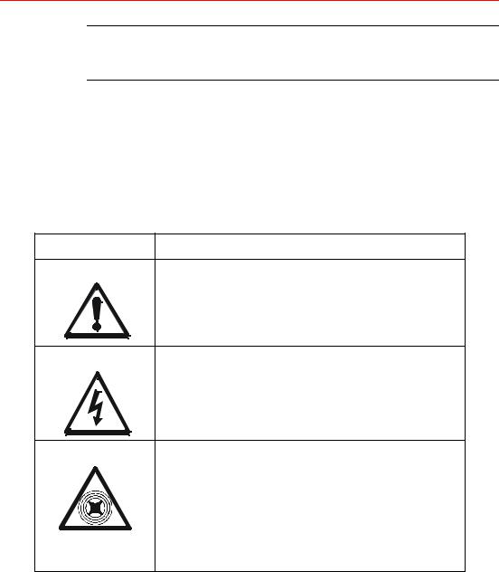
CAUTION:
Exclamation Mark: This icon is used for other instances and items for which a standard symbol does not exist.
CAUTION: Risk of Electric Shock
This icon identifies instances where dangerous or lethal voltages might be present when working with various components of the irradiator or site power.
CAUTION: Microwave Radiation
The Fusion UV Lamp System is powered by high energy RF microwave power which can be dangerous if misused or inadequately shielded. The lamp system should never be turned on if the lamp housing and screen are not intact, or if the microwave leak detector and interlock are not functioning.
Installation, Operation, and Maintenance Manual # 509252 Rev R |
13 |
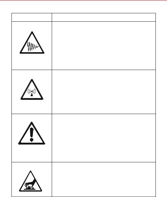
Table 1. Icons (continued)
Icon |
Definition |
|
|
CAUTION: Ultraviolet Radiation
This icon identifies instances where damaging levels of ultraviolet radiation may be present. Adequate shielding around the equipment and region must be provided, and personnel should be required to wear goggles with UV certified lenses. All personnel within ten feet of the lamp should wear gloves and long sleeves to protect their hands and arms, and ensure that their legs are covered.
CAUTION: Radio Interference
Fusion lamps operate at a fundamental frequency of 2.45 GHz. The unit may cause interference with some local area networks (LANs) that also operate at this frequency. Please check with your LAN manufacturer for compatibility. Ensure that the equipment is properly maintained and shielded.
CAUTION: Ozone
High concentrations of ozone can cause discomfort, or at sufficiently high levels be dangerous. Although Fusion lamp systems make ozone at a level that could barely be detected by odor and at a factor of five below the level of 0.1 parts per million allowable for continuous exposure (American Conference of Governmental Hygienists), all Fusion UV Lamp Systems should be exhausted to the outdoors.
CAUTION: Hot Temperature, Do Not Touch
Surface temperatures of the lamp during normal operation may exceed 120o F. Metal components near the lamp will also be hot. Observe appropriate precautions to avoid burns.
14 F300S/F300SQ Ultraviolet Lamp System
|
|
|
|
|
|
|
|
|
Table 1. Icons (continued) |
|
|
|
|
|
|
|
|
|
|
|
|
Icon |
Definition |
||||||
|
|
|
|
|
|
|
|
|
|
|
|
|
|
|
|
|
|
|
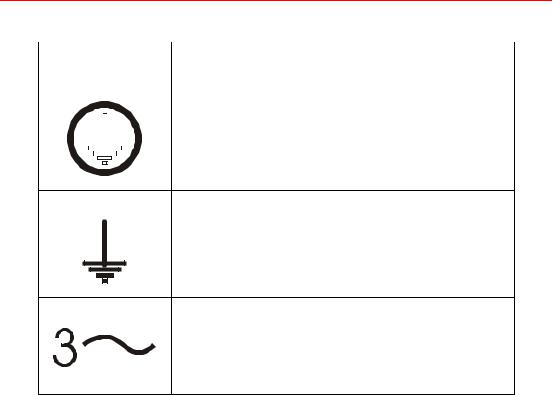
Protective Conductor Terminal |
|
|
|
|
|
|
|
|
|
|
|
|
|
|
|
|
|
|
|
|
|
|
|
|
|
|
|
|
|
|
|
|
|
|
|
|
|
|
|
|
|
|
|
|
|
|
|
|
|
|
Earth (ground) Terminal
Three Phase Alternating Current
System Description
The Fusion Ultraviolet Lamp System has been designed specifically for applications involving the industrial curing of inks and coatings and may be used effectively for a wide variety of applications.
An ultraviolet (UV) lamp system for industrial curing must generate extremely intense radiation in the 200-400 nanometer region. Such radiation, when properly generated and focused, and used in conjunction with specially formulated UV sensitive inks and coatings, causes virtually instantaneous curing (drying) of the exposed materials.
The unique properties of the Fusion UV Lamp System are obtained by using microwave radiation to energize the lamp. Microwave energy at 2450 MHZ is generated by a power tube (magnetron) of the type widely available for commercial microwave cooking ovens. The patented Fusion UV Systems lamp has no electrodes, and consequently overcomes many of the basic limitations of conventional mercury arc lamps.
Installation, Operation, and Maintenance Manual # 509252 Rev R |
15 |

Figure 1. F300S/F300SQ Lamp System
The F300S/F300SQ Fusion UV Lamp System (Figure 1) is modular, consisting of independent 6-inch (15.2 cm) lamp units and corresponding modular power supplies. Two lamps can be placed end-to-end to form a 12-inch (30.5 cm) lamp system or can be placed in a continuous array to form lamps of 18-inch (45.7 cm), etc. This is possible because the illumination of the lamp is a full 6". When two 6" lamps are placed end-to-end forming a 12" lamp, material being irradiated in the focal plane 53.3mm (2.1") below the lamp bottom, and at the juncture between the two lamps, receives sufficient radiation from each 6" module to provide uniform curing over the entire region.
Microwave energy from a single magnetron is directed into the cavity formed by an aluminum reflector and a screen over the bottom of the reflector. The lamp bulb is located inside this chamber. The screen keeps microwaves inside the chamber but allows UV light to pass through onto the material to be cured.
16 F300S/F300SQ Ultraviolet Lamp System

Electrical inputs to the lamp module are provided by a high voltage/control cable with a quick-connect fitting which supplies power for the magnetron, filament transformer and the interlock circuitry.
System Components
The basic F300S/F300SQ system consists of the following items:
•A P300M/P300MQ/P300MT power supply
•An HV Cable H340 (no modular blower)
•An HV Cable H341 (with modular blower)
•An I300 series irradiator
•An RF detector cable H790
•An RF-1 detector
In addition, the user must supply the following if not provided by Fusion UV Systems:
•Cooling for the irradiator, if no modular blower is provided. (See Appendix A, “Specifications” and Appendix C, “Outline Drawings” for irradiator cooling requirements.)
•Mechanical mounting of the lamp modules over a substrate, conveyor, or other transport mechanism
•Light shield surrounding the lamps
•Exhaust system for the light shield
•Any desired interlock mechanisms (see Chapter 3 on page 39)
•Electrical wiring of the power supply into the plant electrical system
Control
The control system of the F300S/F300SQ provides precise control of high voltage and filament voltage supplies. The control board also monitors cooling air pressure, detection of RF, power levels, bulb ignition, and interlocks such as transformer thermal switches. If a problem arises, the control system turns off all high voltage power to the lamp and flashes a fault LED indicator on the power supply control panel.
Inputs for customer ON/OFF control are available. Outputs allow detection of STANDBY or LAMP ON operation, or of interlock failures.
Installation, Operation, and Maintenance Manual # 509252 Rev R |
17 |
Cooling
Proper operation of the lamp requires adequate cooling of the magnetron and the bulb. (See Appendix C, page 129, for irradiator cooling requirements.) Cooling air from a blower goes through the magnetron cooling fins and into the lamp housing. At this point, the airflow splits into two paths: one path exhausts through the irradiator housing vent holes, and the rest of the air flows into the cavity through cooling holes in the reflector. This airflow cools the bulb and exhausts through the RF screen.
Irradiators
The I300M irradiator family is the heart of the UV system. For example, the model I300M contains both the 15.2 cm (6") long electrodeless lamp bulb mounted in the elliptical reflector and the magnetron which energizes the bulb. The reflector is elliptical in cross-section and the lamp bulb is mounted at the focus of the ellipse, producing an intense strip of light at the other focus of the reflector (53 mm [2.1"] below the bottom rails of the lamp).
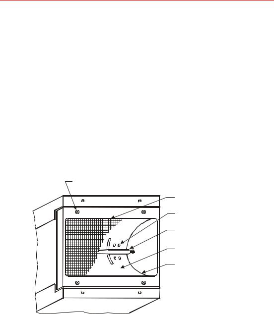
M3 screen retaining screws (4) (2 per side)
RF screen
Cooling air holes
Lamp bulb
Cavity
Reflector
Figure 2. Reflector Assembly
18 F300S/F300SQ Ultraviolet Lamp System

The following table lists the various irradiator models manufactured by Fusion UV Systems, and describes their high-level differences.
Table 2. Irradiator Models
Irradiator Model |
Photoresistor Assembly |
RF Gasket |
Air Delivery |
|
|
|
|
I300M |
Direct View |
Standard |
Front Connect Plenum |
|
|
|
|
I301M |
Direct View |
Standard |
Top Connect Plenum |
|
|
|
|
I300MB |
Direct View |
Standard |
Modular Blower |
|
|
|
|
I310MP |
Scatter View |
I6 |
Front Connect Plenum |
|
|
|
|
I311MP |
Scatter View |
I6 |
Top Connect Plenum |
|
|
|
|
I310MB |
Scatter View |
I6 |
Modular Blower |
|
|
|
|
I310MP-D |
Direct View |
I6 |
Front Connect Plenum |
|
|
|
|
I311MP-D |
Direct View |
I6 |
Top Connect Plenum |
|
|
|
|
I310MB-D |
Direct View |
I6 |
Modular Blower |
|
|
|
|
Reflector and Cavity
The top of the reflector contains two rectangular slots which admit microwave energy into the cavity. The slots are fed by one 1800 W, 2450 MHz magnetron located in the top half of the lamp enclosure and connected to the cavity by a waveguide launcher.
Lamp Bulb
The lamp bulb (Figure 3) is made of quartz and has a tapered shape which optimizes its UV, thermal, and microwave properties. The short quartz stubs at either end of the 15.3 cm (6") bulb provide mechanical support for quick mounting into spring-loaded receptacles at the cavity ends. They are not electrodes and have no electrical function.
Figure 3. Lamp Bulb
Access to the cavity for changing the bulb or routine cleaning of the bulb and reflector is easily accomplished by removing the screws which secure the screen assembly to the bottom of the lamp. This procedure is explained in detail in Chapter 6, “Maintenance”. The fine mesh screen must be intact and firmly secured to the lamp if the system is to work properly and safely. The RF leakage interlock automatically shuts the system off if excess microwave energy passes through the screen.
Installation, Operation, and Maintenance Manual # 509252 Rev R |
19 |

Mounting
The lamps can be mounted over a moving substrate or web, supported by the bottom rails. The lamps should be mounted so that the rails sit 53 mm (2.1") above the surface to be cured. This allows the elliptical reflector to focus the most intense strip of light very near the substrate.
Power Supply
Each lamp system has its own power supply to house the high voltage circuits necessary to energize the magnetron, as well as all control and interlock electronics, and the built-in cooling fan.
The power supply is fully modular. Up to six units may be interconnected and controlled from a single master unit. Any power supply may assume either Master or Slave status in a multi-unit installation.
P300M/P300MQ/P300MT
The power supply high voltage circuit consists of a dual half-wave voltage doubler circuit which supplies a regulated source of high voltage power (approximately 3900V, 700 mA DC) to the magnetron in the irradiator. The capacitors and diodes provide regulation and rectification to the high voltage transformer outputs.
RF Detector
The system includes a detection device which shuts the system down if microwave energy in excess of permissible levels is in danger of being released into the work environment. This might be caused by a faulty RF screen or some other type of damage to the lamp, or by inadequate or damaged shielding.
The power supply fault detection circuitry searches the system for a functioning RF detector by means of the System Interconnections Bus. A multi-unit installation must have at least one RF detector, which is usually connected to the master power supply. Additional detectors may be connected to slave units.
During the startup sequence, each power supply will automatically perform a functional test on any installed RF detector (if switch S1-5 is set to “YES”). The operator may also verify detector operation by pushing a test button on the RF-1 module for 4 seconds. Complete information appears in Chapter 5, “Troubleshooting”.
System Interconnections
All electrical connections to the power supply are made through connectors at the rear. Instructions for wiring are provided in Chapter 3, “Electrical System”. The power supply does not require any routine maintenance other than occasional cleaning of the interior with compressed air (depending on the environment).
20 F300S/F300SQ Ultraviolet Lamp System
Figure 4. P300M Front Panel
Warranty Policy
Items manufactured by Fusion UV Systems Incorporated are warranted (under normal and proper use) to be free from defects in material and workmanship. Fusion UV Systems will repair or replace, at its option, any defective parts when returned to Fusion by the purchaser, transportation paid. See the Terms & Conditions included with your sales order for the length of the warranty period.
Equipment may not be returned, whether for warranty or other purposes, without prior authorization and issuance of a Returned Material Authorization Number by Fusion UV Systems. After inspection and acceptance, equipment returned for credit will be subject to a handling and restocking charge.
Fusion UV Systems assumes no expense or liability for repairs made outside its plant without written consent nor for any labor costs which are so incurred. For equipment manufactured by others, Fusion UV Systems will pass along to the purchaser whatever warranty it receives and will not be responsible for any incurred expense outside of such warranty.
If repair of equipment is required but return of such equipment to Fusion UV Systems is not feasible, then by mutual consent of Fusion and the purchaser, an authorized Fusion UV service representative will be sent to the purchaser’s plant to effect necessary repairs. The purchaser will be charged for the representative’s time and expense.
The two consumable items in a Fusion UV lamp system are the lamp bulb and the microwave power tube (magnetron). The special warranties on these components are detailed on the sales contract.
Installation, Operation, and Maintenance Manual # 509252 Rev R |
21 |

NOTE: Any repairs or alterations, including the use of non-Fusion UV Systems (Fusion) parts, made by the user of this product without Fusion UV Systems’ prior written consent shall void all warranties provided by Fusion UV Systems and such warranties shall cease to be in effect. No allowance will be granted for such repairs or alterations. No person, agent, representative, or distributor is authorized to give any warranties on behalf of Fusion UV Systems, or to accept for Fusion UV Systems any other liability in connection with any of Fusion UV Systems’ products.
Shipping Instructions
Read the following sections carefully to ensure compliance with the requirements and recommendations for returning products or components, whether for credit, replacement, or repairs.
Returned Material Authorization Number
Equipment may not be returned, whether for warranty or other purposes, without prior authorization and issuance by Fusion UV Systems of a Returned Material Authorization Number. After inspection and acceptance, equipment returned for credit will be subject to a handling and restocking charge. Returned equipment must be shipped prepaid.
General Packing Instructions
If possible, original packaging materials should be reused for return shipment to Fusion UV Systems. If Fusion UV Systems’ packaging materials are not used, equivalent packaging, as outlined in the following sections, is to be used.
Power Supply
Secure the chassis to the cover by M5 x 12 mm screws. (There are three on each side of power supply for the P300M/P300MQ, two on each side of power supply for the P300MT.)
Box: |
Bursting Test: 24 kg/cm2 (350 lbs./sq. in.) |
Gross Weight Limit: 70 kg (155 lbs.)
Fills: |
Rigid high density styrofoam or cardboard fills as required to |
|
ensure power supply does not shift in box during shipment. |
CAUTION: Packaging materials should not push against connectors or controls.
22 F300S/F300SQ Ultraviolet Lamp System

Irradiators
Irradiators should be returned in their original packaging. If this is not available, lamps must be double boxed, as follows:
The lamp is to be placed in an inner box, using cardboard fills to assure a snug fit. The RF screen should be protected by taping a piece of cardboard over it. The inner box should then be placed in an outer box that provides about a two-inch clearance on all sides. High density styrofoam corner pads should be placed in the corners between the outer and inner boxes to isolate the lamp from impact.
Box: |
Bursting test: 24 kg/cm2 (350 lbs./sq. in.) |
Gross Wt. Limit: 70 kg (155 lbs.)
Magnetrons
If available, use a special Fusion replacement magnetron shipping box. Otherwise, magnetrons must be double boxed as described next.
Wrap magnetrons in three layers of plastic “bubble wrap” or equivalent. Place magnetrons in the box and add loose styrofoam fill. Place this inner box in an outer box and surround the inner box with loose styrofoam fill.
UV Bulbs
Place the bulb in a rigid tube (use Fusion UV Systems’ plastic lamp bulb replacement shipping tube if available.) Secure ends to prevent impact against the tube and wrap the tube in three layers of plastic “bubble wrap” or equivalent. Ship with loose styrofoam fill in the box.
Control Cards
The integrated circuits in control board assemblies are susceptible to damage from static electrical charges which may be transmitted by handling or packaging materials. To guard against static, place control cards in anti-static bags, if available. If not, wrap control cards in aluminum foil. Isolate the cards from impact with additional wrapping of “bubble wrap” or equivalent.
RF Detectors
RF Detectors should be wrapped in two layers of “bubble wrap” or equivalent and placed in a box with loose styrofoam fill.
Installation, Operation, and Maintenance Manual # 509252 Rev R |
23 |

24 F300S/F300SQ Ultraviolet Lamp System
Chapter 1. Safety
Fusion UV Systems’ Ultraviolet (UV) Lamp Systems have been designed to operate safely. Many systems are in production in a wide variety of industrial environments without any problems of worker safety or health hazards. However, like most industrial equipment, this equipment can present worker safety problems if care is not taken to install, operate, and maintain it correctly.
The following pages provide information concerning various aspects of worker safety with regard to this equipment. Because some features of the system may be new to personnel using the equipment, an attempt has been made to provide a fairly extensive background on these issues as well as references, where feasible, to further information or U.S. Government Standards.
IMPORTANT: All personnel using the equipment must become familiar with this safety information.
Care in installation and operation, coupled with adequate worker training, should ensure that no unusual safety problems arise.
Installation, Operation, and Maintenance Manual # 509252 Rev R |
25 |
Ultraviolet Radiation
Ultraviolet radiation which is emitted during normal operation of the Fusion Ultraviolet Lamp System can be dangerous to the eyes and skin of personnel. Adequate shielding around the system and the region to be irradiated must be provided. If unsafe levels of light are allowed to escape during operation, then all personnel in the vicinity of the lamps should be required to wear goggles with UV certified lenses. Protection is needed for indirect as well as direct eye exposure; UV certified lenses are recommended. Discomfort from excessive eye exposure to ultraviolet light typically occurs about six hours after exposure. Personnel who experience eye pain after possible exposure to direct rays from the UV lamp should see a doctor. Furthermore, in the event that adequate shielding is not possible, all personnel within ten feet of the lamp should wear gloves and long-sleeved shirts to protect hands and arms.
There are no present U.S. government standards on worker exposure to ultraviolet light. However, there is a NIOSH document, “Criteria for a Recommended Standard...Occupational Exposure to Ultraviolet Radiation” (No. HSM 73-11009), and several useful publications are available from the Bureau of Radiological Health of the Food and Drug Administration.
Microwave Radiation
The Fusion UV Lamp System is powered by high energy RF microwave power. This form of energy is identical to that used in home microwave ovens and, as in the case of ovens, can be dangerous if misused or inadequately shielded. In the Fusion UV lamp, the shielding is adequate only as long as the lamp and the screen on the bottom of the lamp are intact. Any rip or large hole in the screen may lead to microwave radiation leakage in dangerous amounts. The power to the lamp is interlocked to shut off if there is excessive microwave radiation leakage. The lamp system should never be turned on if the lamp housing and screen are not intact, or if the microwave leak detector and interlock are not functioning.
Fusion UV equipment is interlocked to shut down if microwave leakage in excess of 5 mW/cm2 (milliwatts per square centimeter) is detected.
26 F300S/F300SQ Ultraviolet Lamp System
Personnel Effects of Microwave Radiation
OSHA (U.S. Department of Labor, Occupational Safety, and Health Administration - Standard 29CFR 1910.97) and ANSI (American National Standards Institute - Standard C95.1-1999) are the only major national organizations with voluntary guidelines for safe limits of occupational microwave radiation exposure.
The ANSI recommendation is the more stringent of the two guidelines. Conservatively expressed, it states that a worker should not be exposed to microwave radiation levels in excess of 8 mW/cm2 on a continuous basis at 2.45 GHz. It allows for short-term exposure to much higher levels by stating that over a six-minute period the average
power density to which a worker is exposed to microwave radiation should not exceed 8 mW/cm2.
Microwave radiation is considered a non-ionizing electromagnetic radiation, which is not known to produce genetic damage. The primary effect of this energy is to simply raise the temperature of a body which absorbs it. For example, 5 mW/cm2 will raise 1 cc of water 0.07o C in one minute. If the average worker were exposed to this energy level continuously, he would absorb about 30 watts over his whole body. At rest, the body dissipates about 100 watts. Therefore, this additional heat load is considered safe, although we do not recommend continuous exposure to levels anywhere near 5 mW/cm2.
Fusion UV Systems equipment normally produces low level leakage well below 8mW/cm2 in the work environment. If a microwave survey meter is used, one should read levels well below 1 mW/cm2 where personnel are likely to be continuously exposed. When a lamp is started, leakage levels may increase by a factor of two or three for the few seconds it takes to start and couple energy to the bulb. This is considered safe due to the requirement to average under 8 mW/cm2 over a six-minute period.
Radio Interference
Fusion UV lamps are classified as non-consumer industrial, scientific and medical equipment, as defined in Federal Communication Commission (FCC) Rules and Regulations Volume 47, Part 18. As required by these rules, Fusion UV Systems verifies that their systems are capable of compliance with applicable technical standards governing radiated emissions when the equipment is properly maintained and is installed in an appropriate light shield.
Fusion lamps operate at a fundamental frequency of 2.45 GHz. The unit may cause interference with some local area networks (LANs) that also operate at this frequency. Please check with your LAN manufacturer for compatibility.
Installation, Operation, and Maintenance Manual # 509252 Rev R |
27 |
Ozone
Ozone is a gaseous form of oxygen which is formed by ultraviolet light. It has a characteristic pungent odor to which most people are quite sensitive (people can typically detect concentrations of several parts per hundred million). At high concentrations it can cause discomfort or at sufficiently high levels be dangerous.
The Fusion UV Lamp System makes less ozone than a conventional arc lamp. For example, a pair of lamps running for twelve hours in a non-vented room resulted in a steady state concentration of less than 0.02 parts per million. This was a level that could barely be detected by odor and a factor of five below the level of 0.1 parts per million allowable for continuous exposure (American Conference of Governmental Hygienists).
All Fusion UV Lamp Systems should be exhausted to the outdoors.
Temperature
Surface temperatures of the lamp during normal operation may exceed 120o F. Metal components near the lamp will also be hot. Before attempting service procedures on the lamp, allow the unit to operate in STANDBY so that the blower continues to run. The bulb will cool completely in less than one minute. If the blower is not allowed to run, the bulb will retain heat for several minutes. Observe appropriate precautions to avoid burns.
Handle the bulb with cotton or surgical gloves or a lint-free towel at all times, as fingerprints can be etched into the quartz.
28 F300S/F300SQ Ultraviolet Lamp System
High Voltage
Insulated electrical cables carry power at 3900 Volts from the power supply to the lamp. These voltages can be dangerous, so some precautions should be taken in both the location and protection of these lines. High voltages are exposed within the power supply chassis, which should never be operated without its cover.
DANGER: Never touch the power supply/lamp cable connections while the system is ON or in STANDBY. A faulty magnetron may cause 7000 Volts DC to appear on connector pins and may cause serious injury.
Do not touch power supply/irradiator harness plug P10 near the contacts, and do not lay P10 down on any conductive material.
Never troubleshoot the power supply without first disconnecting all external power and discharging the high voltage capacitors with an insulated screwdriver.
A high quality cable, rated at 10,000 Volts, is used in all high voltage cables manufactured by Fusion UV Systems, and can be supplied to users for any additional connections that may be required.
UV Curable Materials
Please consult your UV materials supplier for recommended precautions regarding the proper handling and use of these products.
Installation, Operation, and Maintenance Manual # 509252 Rev R |
29 |

30 F300S/F300SQ Ultraviolet Lamp System
 Loading...