

Page 1

INMARSAT MINI-C
MOBILE EARTH STATION
FELCOM 16
www.furuno.co.jp
Page 2

9-52 Ashihara-cho,
*
00080934514
**00080934514
*
Nishinomiya, 662-8580, JAPAN
Telephone : +81-(0)798-65-2111
Fax :+81-(0)798-65-4200
The paper used in this manual
is elemental chlorine free.
・FURUNO Authorized Distributor/Dealer
All rights reserved.
Pub. No. OME-56380-E1
(TATA ) FELCOM16
Printed in Japan
A : MAY 2003
E1 : MAY 07, 2007
*00080934514**00080934514*
* 0 0 0 8 0 9 3 4 5 1 4 *
Page 3

IMPORTANT NOTICES
• This manual is intended for use by native speakers of English.
• No part of this manual may be copied or reproduced without written permission.
• If this manual is lost or worn, contact your dealer about replacement.
• The contents of this manual and equipment specifications are subject to change without
notice.
• The example screens (or illustrations) shown in this manual may not match the screens
you see on your display. The screen you see depends on your system configuration and
equipment settings.
• Store this manual in a convenient place for future reference.
• FURUNO will assume no responsibility for the damage caused by improper use or
modification of the equipment (including software) by an unauthorized agent or a third
party.
• When it is time to discard this product it must be done according to local regulations for
disposal of industrial waste. For disposal in the USA, refer to the Electronics Industries
Alliance (http://www.eiae.org/).
i
Page 4
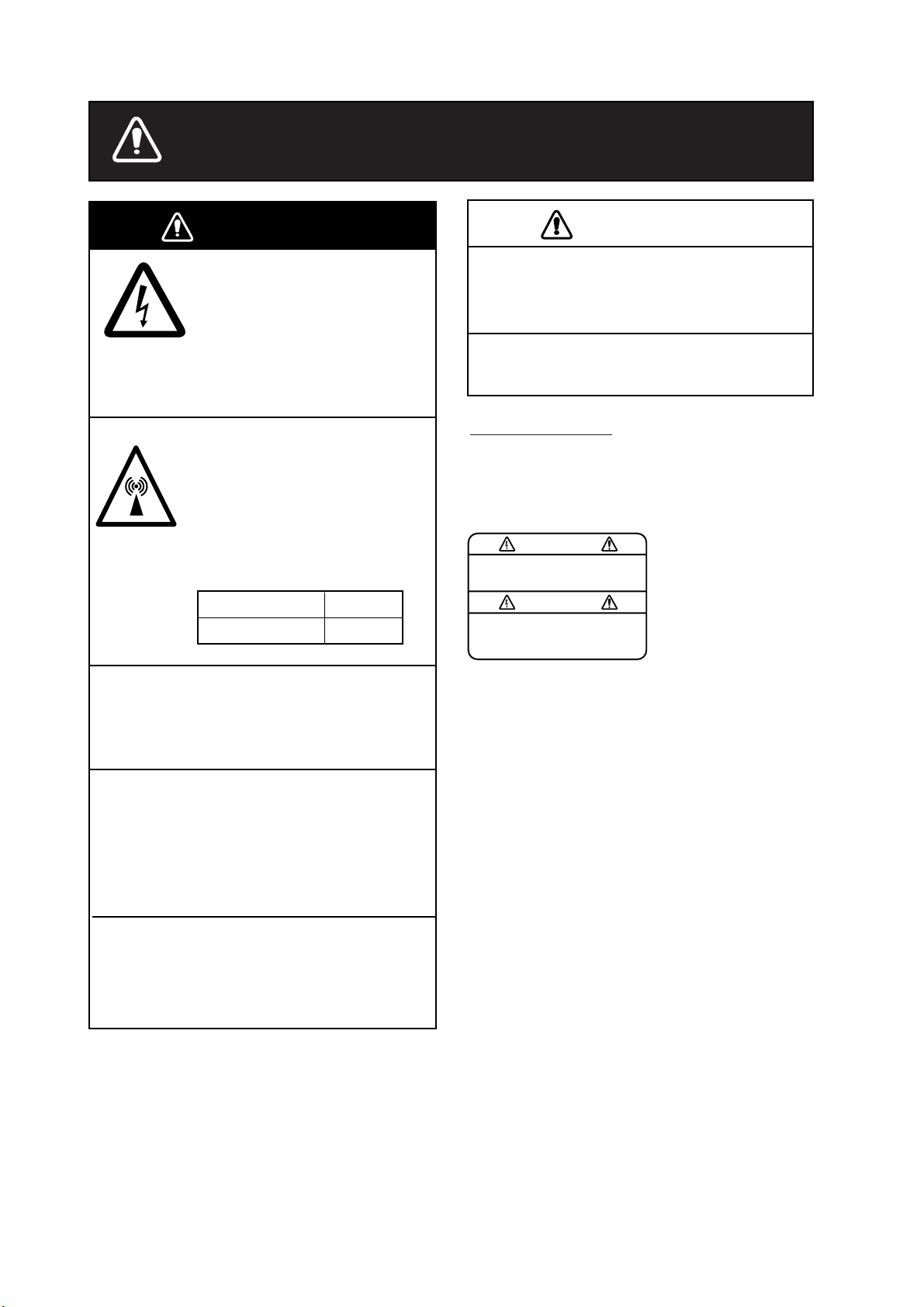
SAFETY INSTRUCTIONS
WARNING
Do not open the equipment.
Hazardous voltage which can
cause electrical shock, burn
or serious injury exists inside
the equipment. Only qualified
personnel should work inside
the equipment.
Hazardous microwave.
Do not approach within
60 cm of the antenna radome
when it is transmitting.
Microwave radiation can be
harmful to the human body,
particularey the eyes.
Radiation Level At
10W/m
2
60 cm
CAUTION
Use the proper fuse.
Use of a wrong fuse can result in fire or
permanent damage to the equipment.
This equipment is intended for marine
application.
WARNING LABEL
A warning label is attached to the
communication unit. Do not remove the
label. If the label is missing or damaged,
contact your dealer about replacement.
WARNING
To avoid electrical shock, do not
remove cover. No user-serviceable
parts inside.
Name: Warning Label (1)
Type: 86-003-1011-1
Code No.: 100-236-231
Do not disassemble or modify the
equipment.
Fire, electrical shock or serious injury can
result.
Turn off the power immediately at the
ship's mains switchboard if water
leaks into the equipment or the equipment is emitting smoke or fire.
Continued use of the equipment can cause
fire or electrical shock.
Any repair work must be done by a
licensed radio technician.
Improper repair work can cause electrical
shock or fire.
ii
Page 5

TABLE OF CONTENTS
FORWARD .......................................................................................................... vii
SYSTEM CONFIGURATION................................................................................ ix
INMARSAT C SYSTEM OVERVIEW .................................................................... x
1. OPERATIONAL OVERVIEW......................................................................... 1-1
1.1 Communication Unit ..................................................................................................1-1
1.1.1 Turning the power on/off.................................................................................. 1-1
1.1.2 Diagnostics...................................................................................................... 1-1
1.2 Terminal Unit (PC) Operation.....................................................................................1-2
1.2.1 Starting, quitting the application....................................................................... 1-2
1.2.2 Controls description......................................................................................... 1-3
1.2.3 Shortcut keys .................................................................................................. 1-4
1.2.4 Function keys..................................................................................................1-5
1.3 Standby Display......................................................................................................... 1-6
1.3.1 Display indications...........................................................................................1-7
1.4 Menu Overview........................................................................................................ 1-11
1.5 Error Messages and Alerts....................................................................................... 1-12
1.6 Choosing a Printer................................................................................................... 1-13
2. SYSTEM INITIALIZATION ............................................................................2-1
2.1 System Settings......................................................................................................... 2-1
2.2 PC Window Setup......................................................................................................2-3
2.3 Login and Logout....................................................................................................... 2-5
2.3.1 Login ............................................................................................................... 2-5
2.3.2 Logout.............................................................................................................2-7
2.4 EGC Settings............................................................................................................. 2-8
2.4.1 What is the EGC (Enhanced Group Call) service? .......................................... 2-8
2.4.2 EGC setup.....................................................................................................2-10
2.4.3 Adding EGC channels................................................................................... 2-13
2.4.4 Saving, printing EGC messages automatically .............................................. 2-15
2.5 Adding NCS Channels.............................................................................................2-17
2.6 LES List...................................................................................................................2-19
2.6.1 Setting toll charges........................................................................................ 2-19
2.6.2 Registering LES to LES list ........................................................................... 2-21
2.6.3 Editing the LES list. ....................................................................................... 2-22
2.6.4 Printing the LES list....................................................................................... 2-23
2.7 Station List............................................................................................................... 2-24
2.7.1 Adding stations to the station list ................................................................... 2-24
2.7.2 Editing the station list.....................................................................................2-28
2.7.3 Printing the station list ................................................................................... 2-29
2.8 Entering Own Ship’s Position...................................................................................2-30
2.9 Creating A Directory................................................................................................. 2-31
2.9.1 Creating a directory where to store messages...............................................2-31
2.9.2 Specifying directory where to store messages............................................... 2-33
iii
Page 6

TABLE OF CONTENTS
v
2.10 E-mail Service/SMS Station List .............................................................................. 2-34
2.11 E-mail Setup............................................................................................................ 2-37
2.12 Saving, Loading System Settings............................................................................ 2-38
2.12.1 Saving system settings to a floppy disk......................................................... 2-38
2.12.2 Loading system settings to the terminal unit.................................................. 2-38
3. FILE OPERATIONS....................................................................................... 3-1
3.1 Files and Working Areas............................................................................................ 3-1
3.2 Preparing Files .......................................................................................................... 3-2
3.2.1 Preparing a routine file.................................................................................... 3-2
3.2.2 Preparing a confidential file............................................................................. 3-3
3.2.3 Editor menu setup........................................................................................... 3-4
3.2.4 Working with text............................................................................................. 3-5
3.3 Saving Files............................................................................................................. 3-10
3.3.1 Save file, retain place on screen ................................................................... 3-10
3.3.2 Save file, clear screen....................................................................................3-11
3.4 Opening Files .......................................................................................................... 3-12
3.4.1 Opening files................................................................................................. 3-12
3.4.2 Switching between files................................................................................. 3-12
3.4.3 Opening a file when both working areas are occupied .................................. 3-13
3.5 Saving a File Under a New Name ........................................................................... 3-14
3.6 Printing Files ........................................................................................................... 3-15
3.7 Combining Files....................................................................................................... 3-15
3.8 Deleting Files .......................................................................................................... 3-16
3.9 Renaming Files ....................................................................................................... 3-17
3.10 Decoding E-mail Attachment ................................................................................... 3-18
4. INMARSAT C COMMUNICATIONS .............................................................. 4-1
4.1 Transmitting............................................................................................................... 4-1
4.1.1 Code description............................................................................................. 4-1
4.1.2 Transmitting prepared message...................................................................... 4-2
4.1.3 Transmitting a file stored on the hard disk..................................................... 4-15
4.1.4 Canceling transmission on a message awaiting transmission ....................... 4-16
4.1.5 Requesting delivery status............................................................................ 4-17
4.1.6 Accessing the code number services............................................................ 4-20
4.1.7 Displaying the send message log.................................................................. 4-22
4.2 Receiving ................................................................................................................ 4-23
4.2.1 When a message is received ........................................................................ 4-23
4.2.2 Setting the receive alarm .............................................................................. 4-24
4.2.3 Displaying, printing received messages .........................................................4.24
4.2.4 Automatically printing received messages .................................................... 4-28
4.2.5 Saving received messages to the hard disk .................................................. 4-28
4.2.6 Automatically saving received messages to the hard disk............................. 4-29
4.2.7 Deleting received messages......................................................................... 4-30
4.3 Display Log ............................................................................................................. 4-31
4.3.1 Displaying and printing the display log. ......................................................... 4-31
4.3.2 Automatic printing of display log.................................................................... 4-32
i
Page 7

TABLE OF CONTENTS
4.4 EGC Messages........................................................................................................4-33
4.4.1 Displaying and reprinting EGC messages. .................................................... 4-33
4.4.2 Displaying EGC closed network ID (ENID) .................................................... 4-34
4.4.3 Displaying the EGC message log .................................................................. 4-35
5. DATA REPORTING AND POLLING..............................................................5-1
5.1 Data Reporting...........................................................................................................5-1
5.1.1 Setting a data report........................................................................................ 5-2
5.1.2 Setting a message report ................................................................................ 5-4
5-1.3 Automatic printing of data report, polling command......................................... 5-7
5.2 Polling........................................................................................................................ 5-8
5.2.1 Polling commands........................................................................................... 5-8
5.2.2 Other polling commands................................................................................ 5-10
5.2.3 Polling reception............................................................................................ 5-11
5.3 DNID (Data Network Identification) ..........................................................................5-12
5.3.1 Displaying DNID............................................................................................5-12
5.3.2 Enabling/Disabling DNID...............................................................................5-13
6. OTHER FUNCTIONS .................................................................................... 6-1
6.1 Aborting an Operation................................................................................................ 6-1
6.2 Scanning NCS Common Channel.............................................................................. 6-2
6.3 Choosing EGC Receiving Channel............................................................................ 6-3
6.4 Choosing NCS Channel.............................................................................................6-4
6.5 LES Information......................................................................................................... 6-5
7. MAINTENANCE, TROUBLESHOOTING...................................................... 7-1
7.1 General Checking and Maintenance..........................................................................7-1
7.2 Diagnostics................................................................................................................7-2
7.2.1 Self test at power on........................................................................................7-2
7.2.2 Testing the communication unit through the keyboard, displaying program
version no........................................................................................................7-2
7.3 Performance Verification (PV) Test. ........................................................................... 7-4
7.3.1 PV test sequence ............................................................................................ 7-4
7.3.2 PV test procedure............................................................................................7-5
7.3.3 Results of PV test............................................................................................7-6
7.4 System Status Monitor............................................................................................... 7-7
7.5 Replacing the Fuse.................................................................................................... 7-8
7.6 Error Messages ......................................................................................................... 7-9
7.6.1 Equipment trouble messages.......................................................................... 7-9
7.6.2 Warning messages........................................................................................7-10
v
Page 8

TABLE OF CONTENTS
APPENDIX ......................................................................................................AP-1
Menu Tree.......................................................................................................................AP-1
International Telex/Telephone Country Code List.............................................................AP-8
LES List.........................................................................................................................AP-15
International Telex Abbreviations ...................................................................................AP-16
International Telegraphy Alphabet..................................................................................AP-17
Messages......................................................................................................................AP-18
Parts List .......................................................................................................................AP-21
Parts Location ...............................................................................................................AP-22
SPECIFICATIONS........................................................................................... SP-1
INDEX............................................................................................................... IN-1
vi
Page 9

FOREWORD
Introduction
FURUNO Electric Company thanks you for considering and purchasing the
FELCOM 16 Inmarsat Mini-C Mobile Earth Station. We are confident you will
discover why the FURUNO name has become synonymous with quality and
reliability.
The FELCOM 16 mainly consists of a communication unit and an antenna unit.
Connected to a PC (local supply), the FELCOM 16 provides a wide range of
communication services, such as e-mail and telex, for mobile and fixed terrestrial
subscribers in the Inmarsat C communication network. Its compact size permits
installation where space is limited.
FURUNO designs and manufactures this equipment with much attention to
operation and maintenance simplicity. However, please read and follow the
recommended procedures for operation and maintenance to get the most out of
the equipment.
This manual provides a brief introduction to the Inmarsat C system (pages ix thru
xiv). For more detailed information, refer to the information below.
Inmarsat C Maritime Customer Relations Officer
Maritime Services Operations Department
International Maritime Satellite Organization (Inmarsat)
Address: 99 City Road, London, EC1Y 1AX, UK
Telephone: +44 20 7728 1777 (Switchboard)
Fax: +44 20 7728 1142
URL: www.inmarsat.com
E-mail customer_care@inmarsat.com
vii
Page 10

FOREWORD
Features
• E-mail facility. (To transmit E-mail, register with an LES provider which
provides e-mail services. E-mail charges are calculated separately.)
• Built-in Enhanced Group Call (EGC) receiver. May be set to operate as
EGC-only receiver.
• Store-and-forward telex communication (public telex network)
• Data reporting and Polling
• Diagnostic programs for maintenance
• Menu driven operation
• VMS (Vessel Monitoring System) applicable
Program Number
PC Board Program No. Version No. Date of Modification
TERMINAL 1650166 03 5/2004
RF CON CPU 1650160 03 5/2004
viii
Page 11
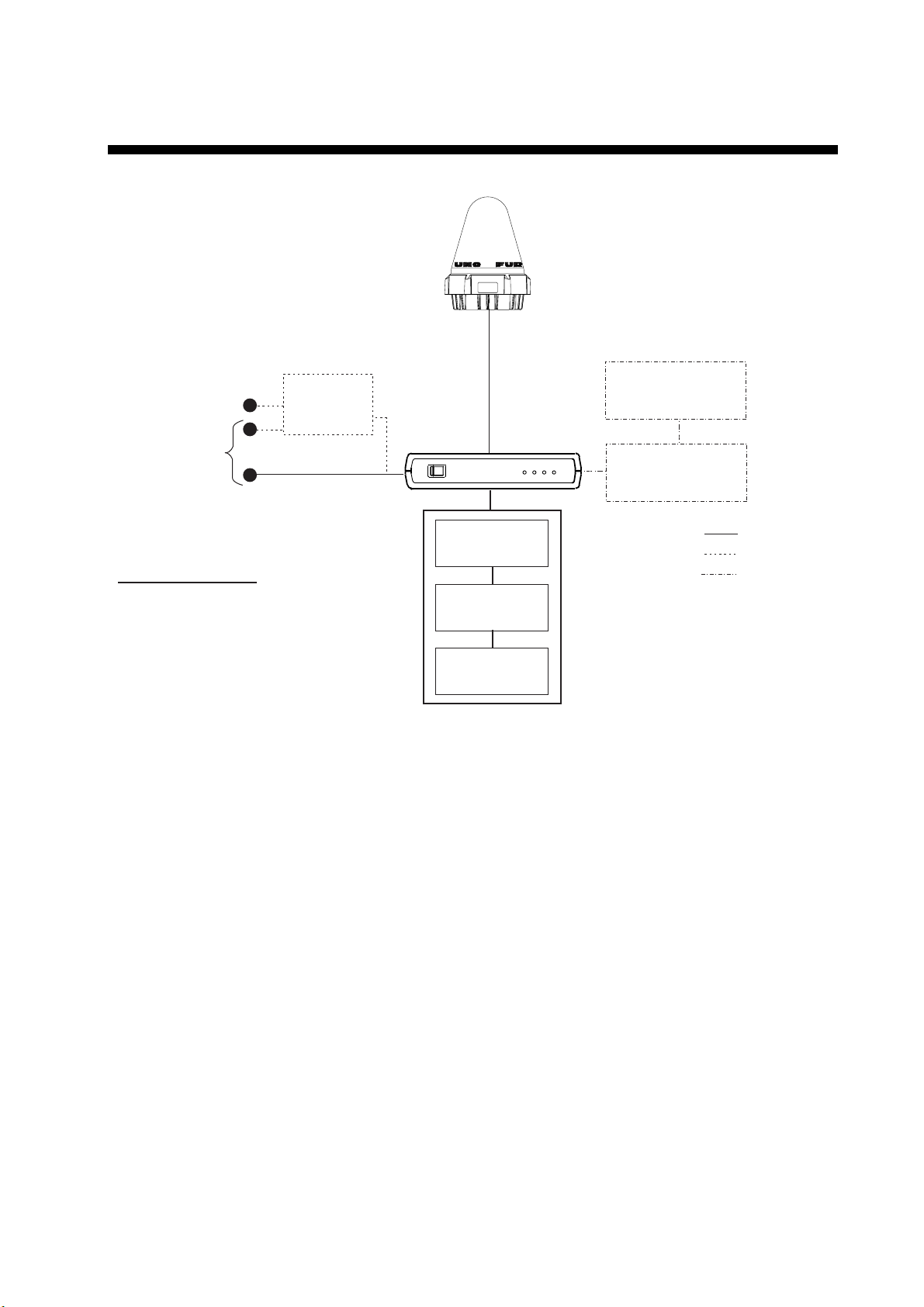
SYSTEM CONFIGURATION
ANTENNA
UNIT
IC-116
SHIP'S MAINS
100-115/200-230 V AC
1φ, 50/60 Hz
SHIP'S MAINS
12-24 VDC
COMMUNICATION UNIT IC-216
(with internal GPS receiver)
CATEGORY OF UNITS
Antenna Unit: Exposed to Weather
Communication Unit: Protected from Weather
Other Units: Protected from Weather
AC-DC
Power Supply
PR-240
INMARSAT MINI-C MOBILE EARTH STATION
FURUNO
POWER
I
O
JUNCTION BOX
IC-315
SSAS ALERT UNIT
IC-307
LOGIN
POWER
TX
ERROR
(PC/AT compatible)
*
PRINTER
PERSONAL
COMPUTER
: Standard
: Option
: Local Supply
* : SSAS Specification
SSAS ALERT UNIT
IC-307
ix
Page 12

INMARSAT C SYSTEM OVERVIEW
Introduction
The Inmarsat C system provides worldwide telex and data transmission and
reception of written information to owners of an Inmarsat C transceiver or a
terrestrial telex network via satellite. Further, e-mail may be sent via the internet.
Communication mode is store-and-forward telex, which means all information
sent are first stored at an LES and then delivered to designated party.
An EGC (Enhanced Group Call) receiver is built in the FELCOM 16 to receive
the following types of messages, broadcast by LESs:
• SafetyNET
distribute maritime safety information to ships within selected areas.
• FleetNET
can use this service to transmit trade information (for example, company
news or market prices) simultaneously to a selected group of ships, to
provide up-to-the-minute information.
• EGC system-related is sent by Inmarsat to certain shipping companies and
geographical areas.
Besides its primary application of ship-shore, shore-ship or ship-ship
communications, the Inmarsat C service has also proved beneficial to trucking
firms who have found it indispensable for communicating with their vehicles. In
this manual, however, we will concentrate on ship applications, the main
application.
TM
-governments and maritime authorities can use this service to
TM
-commercial subscription organizations or shipping companies
x
Page 13
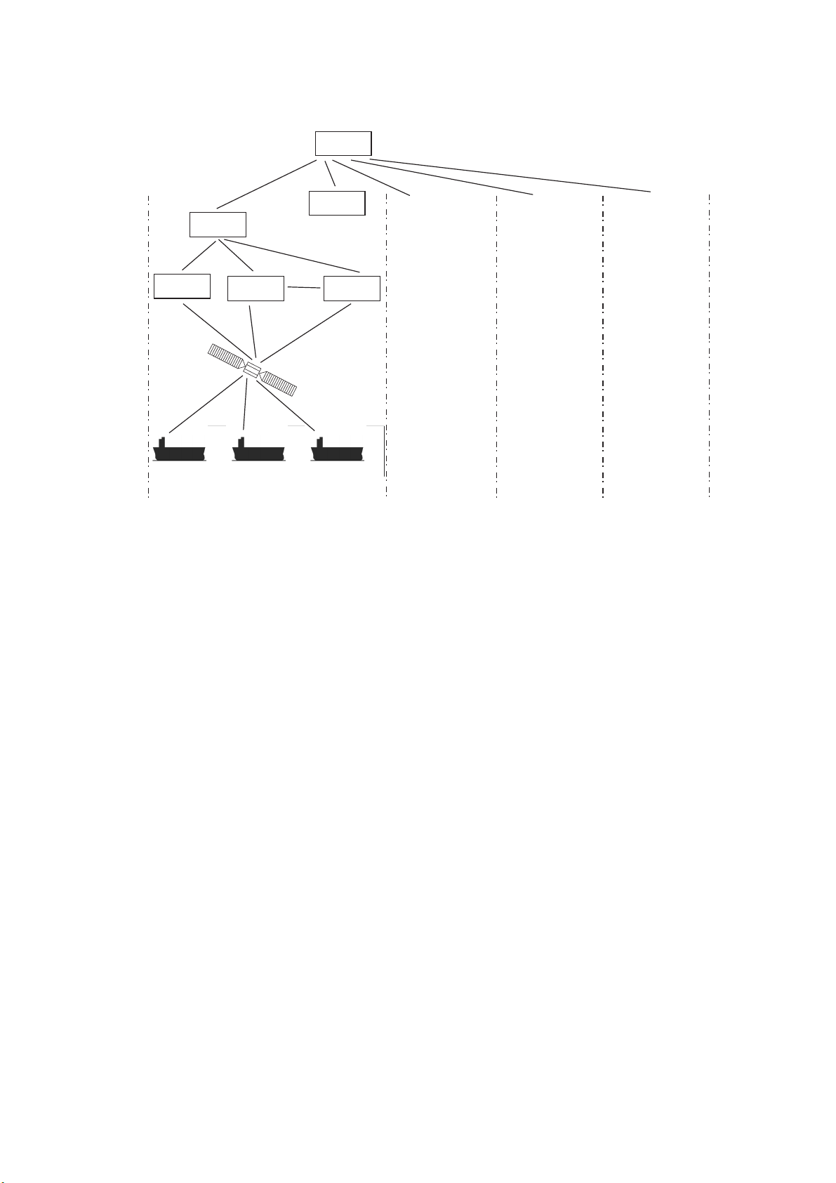
Inmarsat C System Configuration
OCC
SCC
NCS
INMARSAT C SYSTEM
LES
LES LES
Satellite
-/+: To set option
0.0 m
-/+: To set option
0.0 m
-/+: To set option
AOR-West AOR-East IOR POR
OCC: Operation Control Center
SCC:
Satellite Control Center
NCS:
Network Coordination Station
MES:
Mobile Earth Station
LES:
Land Earth Station
Same as left Same as left Same as left
MES
0.0 m
Inmarsat C system configuration
xi
Page 14

INMARSAT C SYSTEM
The Inmarsat C system consists of the Operation Control Center (OCC), Satellite
Control Centers (SCC), Network Coordination Stations (NCS), Land Earth
Stations (LES) and Mobile Earth Stations (MES). The OCC, located at Inmarsat’s
London headquarters, coordinates a wide range of activities in the Inmarsat
system, including commissioning of mobile earth stations.
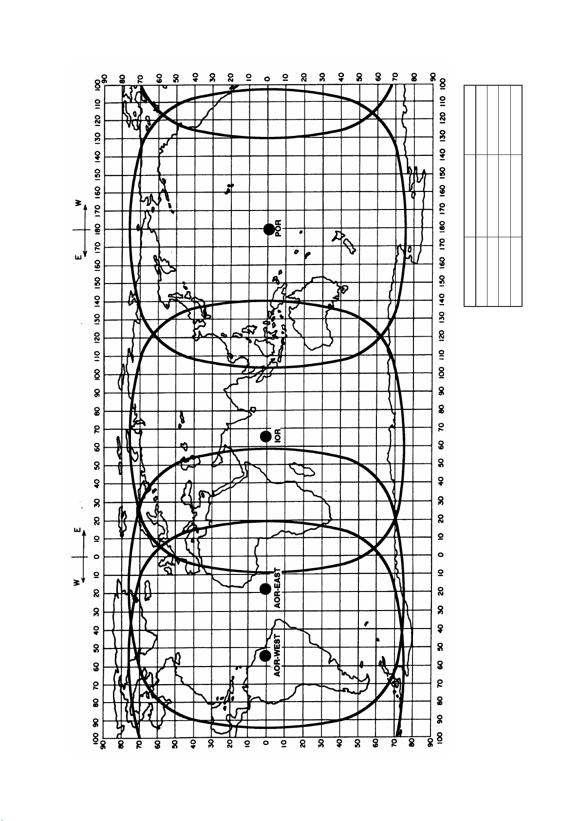
The Inmarsat C system divides the world into four regions and each region is
covered by its own satellite.
Inmarsat system satellites
Region Satellite Satellite Position
AOR-West Inmarsat 3, F4 54.0°W
AOR-East Inmarsat 3, F2 15.5°W
IOR Inmarsat 3, F1 64.0°E
POR Inmarsat 3, F3 178.0°E
In each region there is one NCS and several LESs. The NCS keeps track of all
Inmarsat C transceivers in its region and broadcasts information such as
navigational warnings, weather reports and news. The LESs provide the link
between the MES and the terrestrial telecommunications networks via satellite.
xii
Page 15
INMARSAT C SYSTEM
178°E
64.0°E
15.5°W
INMARSAT-3, F1
INMARSAT-3, F2
IOR
AOR-EAST
54.0°W
INMARSAT-3, F4
AOR-WEST
POSITION
INMARSAT-3, F3
SATELLITE NAME
POR
AREA
Coverage area of Inmarsat satellites
xiii
Page 16
INMARSAT C SYSTEM
v
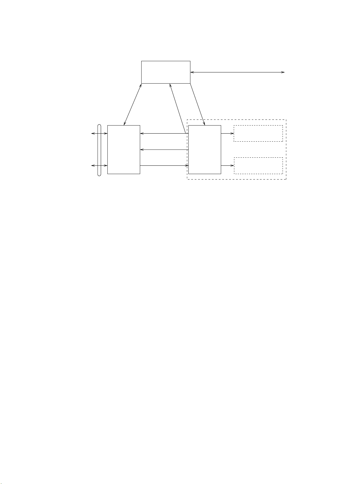
Communications Network
The illustration below shows the Inmarsat C communications network.
Data
Communications
Network
Telex Network
Terrestrial
Communications
Network
NCS common channel The NCS has two major functions:
1) Transmitting information on a common channel.
2) Transmitting EGC messages to MESs.
NCS/LES signaling link This is the link between NCS and all LESs in its
LES TDM channel This channel carries the circuit control signal for
MES message channel This channel carries messages from MES to LES.
MES signaling channel This channel transmits requests, data reports, etc. In
NCS/NCS signaling link This is the link between NCSs. It exchanges data
MES interface The MES consists of the Data Circuit Terminating
Terrestrial network The major functions of the LESs are:
interface
1) Telex store-and-forward conversion
2) Handling EGC messages
3) Data Reporting and Polling
4) Distress message processing
NCS/LES
Signaling Link
Land Earth
Station
(LES)
Network
Coordination
Station (NCS)
MES Signaling
Channel
MES Message
Channel
LES TDM
Channel
NCS/NCS Signaling Link
NCS Common Channel
Data Circuit
Terminating
Equipment
(DCE)
Equipment (DTE)
Enhanced Group
Calling (EGC) Receiver
Mobile Earth
Station (MES)
Data Terminal
Inmarsat C communications network
region. All EGC messages pass through this link.
MES and transmits messages from LES to MES.
addition, it carries login and logout from MES to
NCS.
between MESs operating in different ocean regions.
Equipment (DCE) and the Data Terminal Equipment
(DTE). The DCE consists of the antenna unit, and
the DTE consists of the communications unit and
terminal unit (PC).
xi
Page 17

v
Types of MES
There are three types of MES: class 1, class 2 and class 3. This FELCOM 16
is a class 2 MES.
Class 1: 1) Transmits messages to LES
2) Receives messages from LES
Class 2: 1) The functions of class 1 plus operation as an EGC receiver
2) EGC-only receiver
Class 3: The function of class 1 plus simultaneous operation as an
INMARSAT C SYSTEM
when not transmitting or receiving.
EGC-only receiver.
x
Page 18

INMARSAT C SYSTEM
This page is intentionally left blank.
xvi
Page 19
1. OPERATIONAL OVERVIEW
1.1 Communication Unit
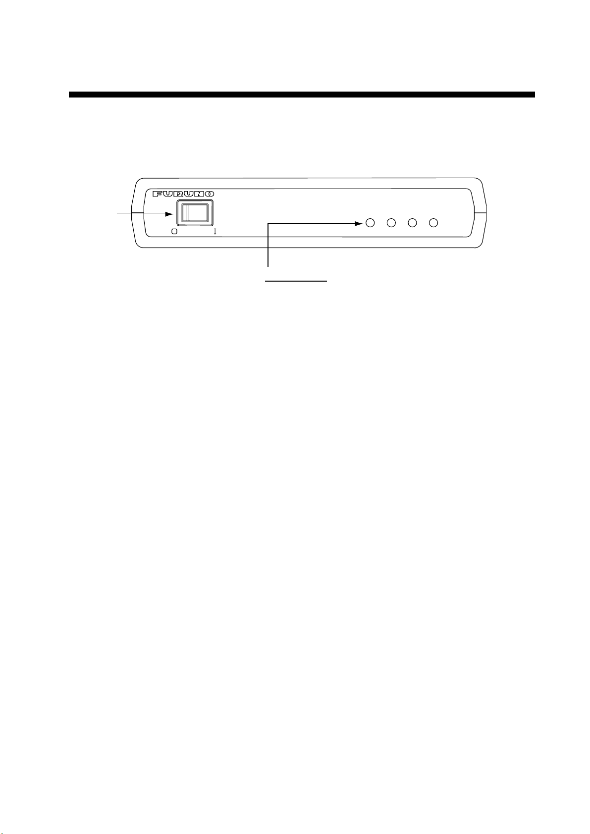
The communication unit is the heart of the FELCOM 16 system, transmitting and
receiving messages via the Inmarsat system.
INMARSAT MINI-C MOBILE EARTH STATION
POWER
Switch
POWER
Status LEDs
POWER: Lights (in green) when power is on.
LOGIN: Lights (in green) when logged in;
TX: Lights (in green) when transmitting.
ERROR: Flashes (in red) for equipment error.
Communication unit IC-216
1.1.1 Turning the power on/off
Press the [POWER] switch to power the communication unit and antenna on or
off.
Note: The example screens shown in this manual may not match the screens
you see on your display. The screen you see depends on your system
configuration and equipment settings.
1.1.2 Diagnostics
POWER
flashes (in green) in green in other instances.
ERROR
TX
LOGIN
When the communication unit is turned on it automatically conducts a series of
diagnostic tests to check itself for proper operation. The test takes about 30
seconds and all lamps are on during the test. For further details, see Chapter 7.
1-1
Page 20

1. OPERATIONAL OVERVIEW
1.2 Terminal Unit (PC) Operation
All operations are carried out from the terminal unit (local supply), through an
easy-to-follow menu system. In this manual the PC is referred to as “Terminal
Unit.” Note that it is necessary to supply a printer.
PC requirements
•
Operating system: Windows98, Windows 2000, Windows ME or
Windows XP
•
Memory: At least 32 MB
•
Free space in hard disk: At least 20 MB
•
CPU: Pentium 100 MHz or higher
•
Floppy disk drive
Windows is a registered trademark of Microsoft Corporation in the US and other
countries used under license.
1.2.1 Starting, quitting the application
For information about terminal unit operation see the PC’s owner’s manual.
1. Turn on the communications unit.
2. Turn on the terminal unit.
3. Double-click the F16PC icon to start the application. After the program has
been loaded the standby display appears. For details about the standby
display see paragraph 1.3.
F16PC icon
Note: The example screens shown in this manual may not match the
screens you see on your display. The screen you see depends on your
system configuration and equipment settings.
4. To quit the application, press the [F12] key while pressing the [Alt] key. The
following display appears. (You may also quit the application by clicking the
Close button at the top right corner of the screen.)
OK to quit system?
Yes
No
5. Press the [←] key to choose Yes and then press the [Enter] key.
6. Turn off the terminal unit in accordance to Windows operating procedure.
7. Turn off the communications unit.
Note: If a different method is used to quit the application, any settings changed
before quitting will not be saved.
1-2
Page 21

1.2.2 Controls description
The FELCOM 16 is almost 100% keyboard controlled. Operation is carried out
with the function keys, numbered F1-F10 at the top of the terminal unit’s
keyboard.
Controls
Esc Cancels key input and returns to previous display screen.
F1-F10 These are the function keys. They choose menus.
Backspace Deletes the character to the left of the cursor.
Insert Works the same as “paste.” See “Copying and pasting text” in
Delete Deletes the character selected with the cursor.
Home Moves the cursor to the top of the message being edited.
End Moves the cursor to the bottom of the message being edited.
PgUp Goes to the previous page of the edit screen.
paragraph 3.2.4.
1. OPERATIONAL OVERVIEW
PgDn Goes to the next page of the edit screen.
[↑], [↓], [←], [→] Control the cursor.
Enter Registers key input.
Shift Chooses upper or lower case alphabet. Press and hold down
the key and then press the [Caps Lock] to get upper or lower
case alphabet. Note that only upper case alphabet are used in
telex.
Alt Executes the shortcut key operation when combined with an
alphabet key. See paragraph 1.2.3.
Space Bar Inserts a space. In addition, it displays the file list, a partial
view of a file, etc., depending on menu.
Caps Lock Turns upper case alphabet input on or off. The Caps Lock LED
lights when upper case input is on.
Tab Inserts horizontal tab characters. The number of tab characters
the key can insert per line of text can be programmed for two,
four or eight tabs.
1-3
Page 22

1. OPERATIONAL OVERVIEW
Ctrl Works in combination with alphabet keys as follows:
Ctrl + [M]: Same as Enter.
Ctrl + [H]: Same As Back Space.
Ctrl + [I]: Same as Insert.
Ctrl + [V]: Same as Overwrite+Insert.
Num Lock Turns numeric input on or off. Note that you cannot enter
alphabet when the Num LED is lit.
Note: In telex, lower case, #, &, *, $, @, %, etc. are not used. A full list of
characters useable in telex appears in the Appendix. For e-mail any
character or symbol may be used.
1.2.3 Shortcut keys
The FELCOM 16 provides the keyboard shortcuts shown below for commonly
used functions.
Shortcut keys
Shortcut key Function
[Alt]+[N] Same as New in File menu
[Alt]+[O] Same as Open in File menu
[Alt]+[Q] Same as Close in File menu
[Alt]+[D] Same as Delete in File menu
[Alt]+[S] Same as Save in File menu
[Alt]+[P] Same as Print in File menu
[Alt]+[X] Same as Undo
[Delete] Same as Cut in Edit menu
[Alt]+[C] Same as Copy in Edit menu
[Insert] Same as Paste in Edit menu
[Alt]+[V] Same as Change Window in Edit menu
1-4
Page 23

1.2.4 Function keys
S
L
The function menus, which you access by pressing the function keys (F1-F10) at
the top of the keyboard, control most operations of this unit.
1. OPERATIONAL OVERVIEW
~
Esc
File
Edit
F1
Transmit
F2 F3
EGC
F4
Reports
F5 F6
Logs
Options
F7
^
F8
Position
Setup
F9 F10
*
Keyboard
Function key description
Menu Description
File (F1) Processes files.
Edit (F2) Provides text editing facilities.
Transmit (F3) Transmits messages.
EGC (F4) Sets up EGC message facilities.
Reports (F5) Sets up data reporting function.
Logs (F6) Displays sent and received message logs.
Options (F7) Login, logout; testing facilities.
Setup (F8) Sets up the system.
Position (F9) Enter your ship’s position manually.
Stop Alarm (F10) Silences audio alarm.
StopAlarm
Prt Sc
Num
Lock
SysRq
*
1-5
Page 24

1. OPERATIONAL OVERVIEW
1.3 Standby Display
After the equipment is turned on and the diagnostic test has been conducted, the
standby display appears, showing the system status monitor. The system status
monitor provides various operating information. For a detailed description, see
paragraph 7.4.
File Edit Transmit EGC Reports Logs Options Setup Position StopAlarm
Date
Time
Position
Waypoint
Course 345 DEG
Speed 10.2 KTS
Current NCS
Current Channel
Current TDM
MES Status
GPS Status
DCE Memory
Current State: IDLE
DCE F16 Ver. ##
## = Version No. of RF CON Board
02-02-25
01:32 (UTC)
LAT 34:30.00N
LON 135:00.00E
LAT
LON
344 (IOR) LOGOUT
NCS CC
NCS CC
Idle
2D
32818 Bytes free
IMN:
BBER
C/N
Send Level
Rx AGC Level
REF Offset Freq
Synthe Local
VCXO Control 131
Antenna Power Supply
Water Temperature
Water Current
Direction
Speed
Depth
UNSYNC
NCS: IOR LOGOUT LAT: 34:30.00N
LON: 135:00.00E
02-02-25 01:32 (UTC)
DEG
DEG
KTS
Standby display
443156710
000
OK ( 0dB)
OK ( 0)
OK (135)
OK ( 0Hz)
OK
OK
After the diagnostic test has been completed, the equipment automatically starts
synchronizing itself with a satellite. When the indication “Retuning” is replaced
with “ SYNC(NCS), the synchronization process is completed. Then, you are
ready to receiving EGC messages. For further details see paragraph 2.4.
1-6
Page 25
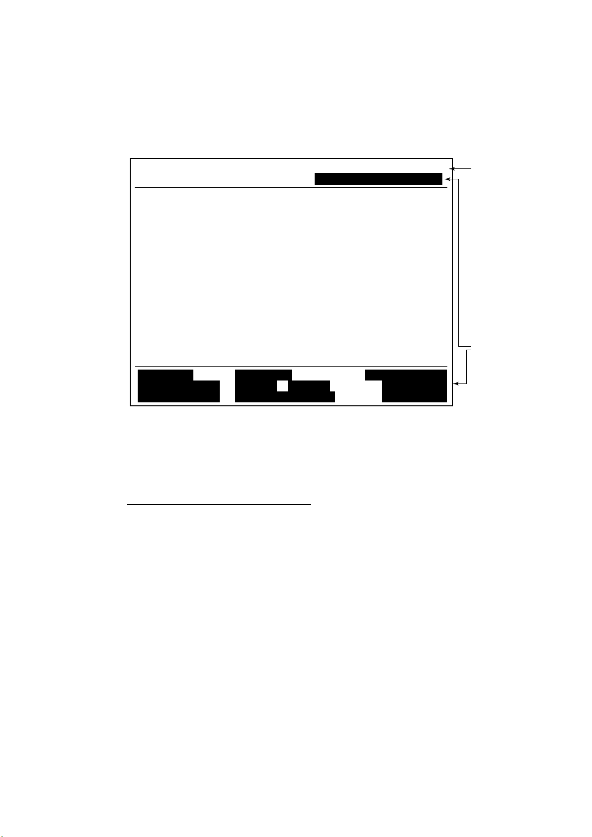
1.3.1 Display indications
The display is divided in three sections:
1) The function menu area
2) The working area
3) The operating status area
1. OPERATIONAL OVERVIEW
File Edit Transmit EGC Reports Logs Options Setup Position StopAlarm
(1) (1)
1) Function
Menu
2) WORKING AREA
3) Operating
Status
(2)
(3a)
(3b)
(4)
(5) (6)
(7)
(8)
(9)
(9)
Location of display indications
Below are the indications and meanings of the items in parentheses in the
illustration above.
(1) Communication network mode
No display Normal operation
Restoration Mode Problem at NCS
(Flashing)
Restoration Mode Previously designated LES is transmitting the
(Reverse video) NCS common channel signal.
1-7
Page 26

1. OPERATIONAL OVERVIEW
(2) Communication unit status
IDLE Idle (awaiting receiving, awaiting transmitting)
IDLE (PENDING) Awaiting reply from LES
SENDING Sending
RECEIVING Receiving
LOGIN Logged in with NCS
LOGOUT Logging out with NCS
Data Report Sending data report
TESTING PV (Performance Verification) testing
TEST SETUP Requesting PV testing
SCANNING NCS scanning
EGC RECEIVER EGC-only receiver operation
(Reverse video)
Delivery Status Req. Transmitting delivery status request
Forced Clearing Stopping receiving, transmitting, or scanning
(3a) Communication status
CALLING Now calling
WAITING FOR ACKNOWLEDGEMENT Waiting for acknowledgement from
LES.
RECEIVING EGC MESSAGE Now receiving EGC message
WAITING FOR BACKOFF Waiting to transmit data report
Successful Login. Login was successful
Login failed. Login failed
Successful Logout. Logout was successful
Logout failed. Logout failed
Successful Forced Clearing. Forced clearing successful
Forced Clearing Failed. Forced clearing unsuccessful
SENDING MESSAGE PACKETS Sending TX message packets
WAITING FOR ACKNOWLEDGEMENT Waiting for acknowledgement from LES
Successful sending to LES. Message successfully sent to LES
Sending message failed. Message could not be sent to LES
Call rejected. LES rejected your message
Call pending. LES temporarily suspending
communications
Received Call. Call received from LES
Received Call(ITA2). Call(ITA2) received from LES
RECEIVING MESSAGE PACKETS Receiving message packets
CLEARING Clearing TX sequence
Successful receiving. You successfully received message
Receiving failed. You could not receive message
Successful Data Report. Data report successfully sent.
Data Report failure. Data report could not be sent.
PV TEST CALL is rejected. PV test call rejected by NCS
PV TEST CALL is pending. PV test pending by LES
TEST-RECEIVING MESSAGE Receiving test message from LES
TEST-SENDING MESSAGE Sending test message to LES
1-8
Page 27

1. OPERATIONAL OVERVIEW
TEST-DISTRESS ALERT Sending test distress alert to LES
WAITING FOR ACTIVATION Waiting start of PV test
WAITING FOR TEST RESULT Waiting for results of PV test
CLEARING Clearing PV test
PV TEST is Completed. PV test is completed.
PV TEST Failure. PV test failed.
(3b) RF CON board program version number
DCE F16 Ver. XX (XX = Version Number)
(4) Frame synchronization
Blank Changing channel, or during transmission
SYNC (NCS) Synchronizing with NCS
SYNC (LES) Synchronizing with LES
MES Sig. Ch Transferring to MES signaling channel
MES Msg. Ch Transferring to MES message channel
UNSYNC Out of synchronization
Retuning Synchronizing with NCS or LES
(5) Ocean region receiving
No display Out of synch with satellite
AOR-W Atlantic Ocean Region-West
AOR-E Atlantic Ocean Region-East
IOR Indian Ocean Region
POR Pacific Ocean Region
(6) Logging status
LOGOUT Logged out with ocean region
LOGIN Logged in with ocean region
LOGIN (Flashing) Logging in with ocean region
1-9
Page 28

1. OPERATIONAL OVERVIEW
(7) Other information
No display No receive message in memory, or printer is
REC. MESSAGE EXISTS Displayed when a routine message has
(Reverse video) not been printed, or a confidential message is
Data Report When data reporting is activated.
(Reverse video)
Message Report Message report setting is activated.
(Reverse video)
(8) Date and time
Date and time, received from the GPS navigator, are displayed. Manually input
date and time are also displayed.
(9) Ship’s position
operating.
received.
Ships position, received from the GPS navigator, is displayed in latitude and
longitude and updated every 30 seconds, or manually input position is displayed.
1-10
Page 29
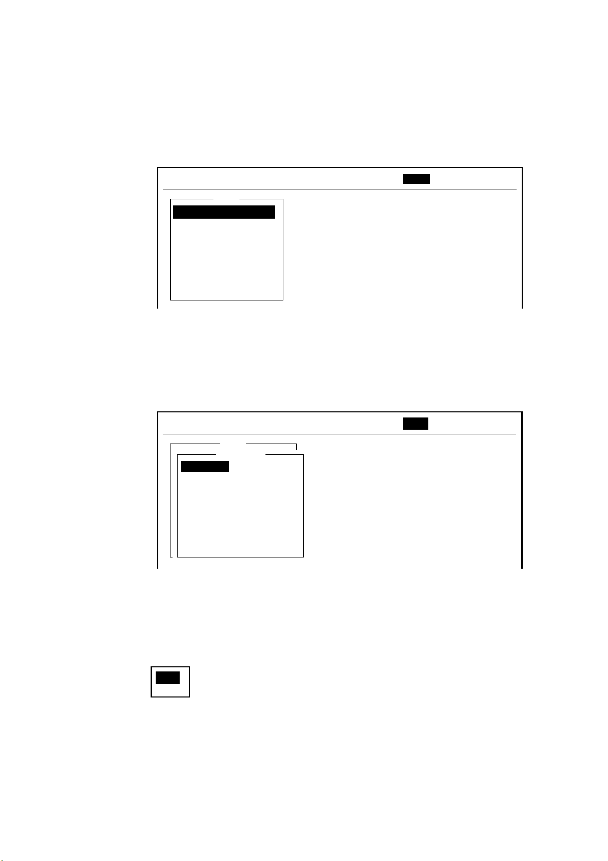
1.4 Menu Overview
Operation of the FELCOM 16 is carried out through a menu system which you
access with the function keys at the top of the screen. The example below
shows how to choose menu options from the Editor Setup menu.
1. Press the [F8] key to display the Setup menu.
File Edit Transmit EGC Reports Logs Options Setup Position StopAlarm
Setup
1. System Setup
2. Editor Setup
3. Terminal Setup
4. EGC Setup
5. Auto Mode Setup
6. E-Mail Setup
7. Directories
8. Configuration
1. OPERATIONAL OVERVIEW
Setup menu
2. Choose desired menu by pressing appropriate numeric key. For example,
press the [2] key to show the Editor Setup menu.
Note: You may also choose a menu by pressing the [↑] or [↓] key to choose it
and then pressing the [Enter] key.
File Edit Transmit EGC Reports Logs Options Setup Position StopAlarm
Setup
Editor Setup
Text Mode
2. System Setup
Edit Mode
3. Editor Setup
Word Wrap
4. Terminal Setup
Line No.
5. EGC Setup
Tab Width
6. Auto Mode Setup
Column Width
7. E-Mail Setup
Cursor Type
8. Directories
Scroll
9. Configuration
Ascii
Insert
ON
ON
4 Char
69
Block
Full Screen
Editor setup menu
3. Choose desired menu item by pressing the [↑] or [↓] keys followed by the
[Enter] key. A window displaying the options for the item selected or a
alphanumeric data entry window appears depending on your selection. For
example, choose Word Wrap.
ON
OFF
Word wrap options window
1-11
Page 30
1. OPERATIONAL OVERVIEW
3. Press the [↑] or [↓] key to choose option desired and press the [Enter] key.
4. Press the [Esc] key.
Note 1: On some menus the update window appears after you press the [Esc]
key. This is done to ask you to confirm settings. Yes is selected in the
Update window; press the [Enter] key to register settings, or press [→]
to choose No and press the [Enter] key to escape.
Update
Yes No
Note 2: The following functions are not available:
Keying Sequence
Item
F3-1 Selection of Priority on Transmit Message
F8-1 NAV PORT, MESSAGE OUTPUT PORT, ACTIVE
PORT, EGC OUTPUT PORT, NETWORK SETUP
on System Setup menu
F8-4 Waypoint on EGC Setup
1.5 Error Messages and Alerts
The terminal unit displays error messages and alerts to call your attention to
misoperation, failed operation and system error. A list of error messages appears
in Chapter 7 and alerts in the Appendix.
To erase an error message or alert, press the [Esc] key.
File Edit Transmit EGC Reports Logs Options Setup Position StopAlarm
Log
1. Send Message Log
2. Receive Message Log
Send Message Log
No. Message File Station LES Priority Send Status Delivery
CAUTION
No Message.
<Press ESC key to continue>
Location of error messages and alerts
1-12
Page 31

1.6 Choosing a Printer
Choose the printer to use as follows:
1. Press the [F1] key to display the File menu.
File Edit Transmit EGC Reports Logs Options Setup Position StopAlarm
File
1. New
2. Open
3. Close
4. Save
ALT-N
ALT-O
ALT-Q
ALT-S
1. OPERATIONAL OVERVIEW
5. Delete
6. Rename
7. Print
8. Print Setting
9. MIME (Decode)
ALT-D
ALT-P
File menu
2. Press the [8] key to choose 8. Print Setting.
Print Setting
Please select Printer
and press Enter key.
No Printer
Windows Printer
PP-510
3. Press the [↑] or [↓] key to choose appropriate printer.
No Printer: Choose this item if no printer is connected.
Windows Printer: Choose if a PC-use printer is connected.
PP-510: Choose if PP-510 is connected.
4. Press the [Esc] key to finish.
1-13
Page 32

1. OPERATIONAL OVERVIEW
(This page intentionally left blank.)
1-14
Page 33

2. SYSTEM INITIALIZATION
This chapter provides the information necessary for initializing the FELCOM 16.
Once the equipment is initialized, you need do no more than press a few keys to
transmit and receive.
Inmarsat assigns an MES an Inmarsat Mobile Number (IMN) when it applies for
Inmarsat registration and it is entered during the installation of the MES. The
IMN is necessary to communicate in the Inmarsat system.
2.1 System Settings
The System Setup menu provides for input of date, time, operating mode, and
port function.
1. Press the [F8] key to choose the Setup menu.
File Edit Transmit EGC Reports Logs Options Setup Position StopAlarm
Setup
1. System Setup
2. Editor Setup
3. Terminal Setup
4. EGC Setup
5. Auto Mode Setup
6. E-Mail Setup
7. Directories
8. Configuration
Setup menu
2. Press the [1] key to display the System Setup menu.
Setup
System Setup
Entered at installation
(Cannot be changed.)
Not used.
System Date & Time
IMN
MES Operation Mode
Nav Port
Active Port
Message Output Port
EGC Output Port
9. Configuration
Network Setup
Command Window
01:53 02-02-25 (YY-MM-DD)
INMARSAT-C
INT
INT
INT
INT
System setup menu
Note: The IMN number is entered during the installation. The number cannot
be changed.
2-1
Page 34

2. SYSTEM INITIALIZATION
3. Press the [↓] key twice to choose MES Operation Mode.
4. Press the [Enter] key to open the MES operation mode options window.
System setup menu, MES operation mode options window
5. Press the [↓] or [↑] key to choose operating mode, INMARSAT-C or EGC.
The INMARSAT-C setting provides telex communications and operates as an
EGC receiver when the equipment is not transmitting or receiving. The EGC
setting enables EGC-only operation. In this case, “Current State: EGC
RECEIVER” (in reverse video) at the bottom of the screen.
6. Press the [Enter] key to close the window.
7. Press the [Esc] key to open the update window.
Setup
System Date & Time
IMN
MES Operation Mode
Nav Port
Active Port
Message Output Port
EGC Output Port
9. Configuration
Network Setup
Command Window
System Setup
01:53 02-02-25 (YY-MM-DD)
IOR
INMARSAT-C
INMARSAT-C
EGC
OFF
INT
EXT
EXT
Setup
System Setup
For technicians
System Date & Time
IMN
MES Operation Mode
Nav Port
Active Port
Message Output Port
EGC Output Port
9. Configuration
Network Setup
Command Window
01:53 02-02-25 (YY-MM-DD)
INMARSAT-C
INT
INT
INT
INT
Update
Yes No
8. Yes is selected; press the [Enter] key to update system settings.
9. Press the [Esc] key to return to the standby display.
Note: If the internal GPS malfunctions, enter data manually as below.
1. Choose System Date & Time from the System Setup menu and then
press the [Enter] key.
Setup
System Setup
02-02-25
System Date & Time
IMN
MES Operation Mode
Nav Port
Active Port
Message Output Port
EGC Output Port
9. Configuration
Network Setup
Command Window
01:53 97-08 (YY-MM-DD)
INMARSAT-C
INT
INT
INT
INT
2-2
Date and time entry window
2. Enter date with the numeric keys.
3. Press the [Enter] key to close the window.
Page 35

2.2 PC Window Setup
The Terminal Setup menu provides for set up of the PC window. Set up includes
selection of date display format, currency unit and window colors.
1. Press the [F8] key to choose the Setup menu.
2. Press the [3] key to display the Terminal Setup screen.
Date Disp. Form
Currency Unit
Screen Saver
Window Color
Terminal Setup menu
3. Date Disp. Form is selected; press the [Enter] key to open its options window.
Terminal Setup
YY-MM-DD
US$
ON
YY-MM-DD
MMM-DD-YY
DD-MMM-YY
2. SYSTEM INITIALIZATION
Date options
4. Press the [↓] or [↑] key to choose date display format desired and then press
the [Enter] key to close the window.
5. Press the [↓] key to choose Currency Unit.
6. Press the [Enter] key to open the currency unit options window.
SDR
US$
EUR
YEN
OTHER
Currency unit options
7. Press the [↓] or [↑] key to choose the currency unit to use to calculate toll
charges. SDR means Special Drawing Right and it is the common unit
charge used by all LES to assess toll charges. For OTHER, enter currency
unit name (4 characters max.). Your selection appears next to Currency Unit
in the Terminal Setup menu.
8. Press the [Enter] key to close the window.
9. Press the [↓] key to choose Window Color and press the [Enter] key.
Window Color
Window Color Setup
Default Color
Window color menu
2-3
Page 36

2. SYSTEM INITIALIZATION
10. You may change the background and foreground colors for the various
display screens on the PC window as follows:
a) Choose Window Color Setup.
b) Window is selected; press the [→] or [←] key to choose the item to adjust.
BASE WINDOW: Standby display
RCV Message Display: Communications memory display
EGC Message Display: Communications display
EDIT1 – EDIT 2 Editor screens
Function: Menu
Sub Menu1 – Sub Menu4: Sub menus
Message: Status message
Window Color Setup
Window : Base Window
Fore Color : L_WHITE
Back Color : BLUE
To Change: ENTER To Change Value: L<=>R
Window color setup menu
MENU
EDIT
File Edit Transmit EGC Reports Logs Options Setup Position StopAlarm
1:
2:
|
|
|
|
|
|
|
< [1] UNTITLED1 >
CAUTION
BASE WINDOW
MESSAGE
Location of items
c) Press the [↓] key to choose Fore Color.
d) Press the [→] or [←] key to choose foreground color desired
e) Press the [↓] key to choose Back Color.
f) Press the [→] or [←] key to choose background color.
g) To change the color of other windows, repeat steps b-f.
h) Finally press the [Enter] key to show the Update window.
i) Yes is selected; press the [Enter] key.
2-4
Note: To restore all default color settings, choose Window Color from the
Terminal Setup menu, choose Default Color and then press the [Enter]
key. Yes is selected; press the [Enter] key.
11. Press the [Esc] key three times to return to the standby display.
Page 37

2.3 Login and Logout
Each time the terminal unit is turned on, register your vessel with the Inmarsat C
system to enable communications between your vessel and an LES. This is
called login.
Note that you can transmit or receive EGC messages even if you are not logged
in.
If you will not be using the FELCOM 16 for a prolonged period, you should
logout from the Inmarsat C system, before turning off the terminal unit. The
Inmarsat C system will then register you as inactive, notifying anyone trying to
call you that you are currently unavailable. If you do not log out before turning off
the power, some LESs may attempt to send a message to you. They may
charge your correspondent, even if you don’t receive the message.
2.3.1 Login
2. SYSTEM INITIALIZATION
1. Confirm that “SYNC (NCS)” appears at the bottom of the screen.
2. Press the [F7] key to display the Options menu.
File Edit Transmit EGC Reports Logs Options Setup Position StopAlarm
Options
1. Login
2. Logout
3. Abort
4. Select NCS
5. Ocean Region
6. LES Information
7. Test
Options menu
3. Press the [1] key to display the Login screen.
Options
Login
Start
Yes
No
Login scree n
2-5
Page 38

2. SYSTEM INITIALIZATION
Note: The terminal unit must be “idle” to login. (“Current State: IDLE”
appears at the bottom of the screen.) When it is not idle, “Ignored:
MES is not idle.” appears. Press the [Esc] key to return to the standby
display. Wait until the terminal unit becomes idle.
4. Yes is selected; press the [Enter] key to start login.
5. Login begins and the screen should now look something like the illustration
below, with “LOGIN” flashing.
File Edit Transmit EGC Reports Logs Options Setup Position StopAlarm
Options
Login
Starting Login Process.
Press any key to escape.
Current State: LOGIN
CALLING
DCE F16 Ver. **
LOGIN replaces IDLE.
SYNC ( NCS )
NCS: IOR LOGIN
Flashing during login
02-02-25 02:02 (UTC)
LAT: 34:30.00N
LON: 135:30.00E
Appearance of display screen during login
When login is completed, the message “Successful login.” appears. Then,
the terminal unit goes into “Idle” status and LOGIN stops blinking.
6. Press any key to return to the standby display.
2-6
Page 39

2.3.2 Logout
1. Press the [F7] key to display the Options menu.
2. Press the [2] key to display the logout screen.
Note: The terminal unit must be “idle” to logout. When it is not idle, “Ignored:
MES is not idle.” appears. Press the [Esc] key to return to the standby
display. Wait until the terminal unit becomes idle.
File Edit Transmit EGC Reports Logs Options Setup Position StopAlarm
2. SYSTEM INITIALIZATION
Options
Logout
Start
Yes No
Current State: IDLE
Successful Login.
DCE F16 Ver.**
SYNC ( NCS )
NCS: IOR LOGIN
02-02-25 02:04 (UTC)
LAT: 34:30.00N
LON: 135:30.00E
Options menu, logout screen
3. Yes is selected; press the [Enter] key to start logout. The screen now looks
something like the illustration below.
File Edit Transmit EGC Reports Logs Options Setup Position StopAlarm
Options
Logout
Starting Logout Process.
Press any key to escape.
Current State: LOGOUT
CALLING
DCE F16 Ver. **
SYNC ( NCS )
NCS: IOR LOGIN
02-02-25 02:02 (UTC)
LAT: 34:30.00N
LON: 135:30.00E
Appearance of display screen during logout
4. When logout is completed, “Successful Logout.” appears. “Current State”
then returns to IDLE.
5. Turn off the FELCOM 16.
2-7
Page 40

2. SYSTEM INITIALIZATION
2.4 EGC Settings
2.4.1 What is the EGC (Enhanced Group Call) service?
The EGC service enables EGC information providers to send SafetyNETTM,
TM
FleetNET
and System messages via an LES to a specific groups of ships, or
to all ships within a defined geographical area.
Each type of EGC service is sent as follows:
1) The information provider prepares the message, and then accesses the
appropriate Country of the international telex network to send the message
to an LES.
2) The LES processes and forwards it to the NCS for the ocean region
designated by the provider.
3) Then, the NCS broadcasts the message throughout the ocean region. (The
operator may choose the EGC messages to receive by position (one
position) and geographical position (nine areas). For further details see
paragraph 2.4.2.)
Satellite
Information Provider
* Meteorological body
* Navtex station
* Coast guard
* Rescue center
* Shipping company,
etc.
LES1
LES2
LES3
Ch1
Ch2
Ch3
NCS
NCS common channel
MES
MES
MES
Ch1-Ch3 are dedicated
channels for each LES.
The EGC system
Three EGC services are available:
1) SafetyNET
TM
This provides a means for information providers to distribute Maritime Safety
Information (MSI) from shore-to-ship. Authorized information providers
include:
a) Hydrographic Offices, for navigational warnings
b) National Weather Services, for meteorological warnings and forecasts
c) Rescue Co-ordination Center, for shore-to-ship distress alerts and other
urgent information
d) International Ice Patrol, for North Atlantic ice hazards
2-8
Page 41

2. SYSTEM INITIALIZATION
2) FleetNETTM
This service allows authorized information providers such as commercial
subscription services, shipping companies and governments, which have
registered with a LES that supports FleetNET
selected group of MESs. Typical applications of FleetNET
TM
, to broadcast messages to
TM
are
a) Fleet or company broadcasts
b) News broadcasts
c) Commercial weather services
d) Market quotations
e) Government broadcasts to all vessels on a country’s registration
3) System
EGC system-related is sent by Inmarsat to certain ship groups and
geographical areas.
2-9
Page 42

2. SYSTEM INITIALIZATION
2.4.2 EGC setup
The FELCOM 16 receives EGC messages directed to its present position and
Navarea without further programming. The EGC Setup screen lets you choose
additional areas for which to receive messages and also the Navtex station and
type of message for Coastal Warning (NAVTEX Re-broadcast).
1. Press the [F8] key to display the Setup menu.
File Edit Transmit EGC Reports Logs Options Setup Position StopAlarm
Setup
1. System Setup
2. Editor Setup
3. Terminal Setup
4. EGC Setup
5. Auto Mode Setup
6. E-Mail Setup
7. Directories
8. Configuration
Setup menu
2. Press the [4] key to display the EGC Setup menu.
Setup
EGC Setup
Receive EGC Area
Notused.
Additional Position
Navarea
Fixed Area
Waypoint (from NAV Equipment)
NAVTEX
Station Code
Type of Message (Can't reject other report)
Ice reports
Meteo. forecasts
Pilot service
DECCA messages
LORAN messages
OFF
OFF
OFF
OFF
OFF
: :
OFF
OMEGA messages
SATNAV messages
Other navaid msg
QRU (no message)
OFF
OFF
OFF
OFF
EGC setup menu
3. The cursor is selecting Additional Position, where you can enter the L/L
position of an ocean region you want to receive broadcasts about. Press the
[Enter] key to open the additional position entry window.
4. Enter position as follows:
a) Enter latitude (XX° XX).
b) Press the [N] or [S] key as appropriate to enter coordinate.
c) Enter longitude (XXX° XX).
d) Press the [E] or [W] key as appropriate enter coordinate.
5. Press the [Enter] key to close the additional position entry window.
6. Press the [↓] key to choose Navarea.
2-10
Page 43

2. SYSTEM INITIALIZATION
7. Press the [Enter] key to open the navarea entry window.
Setup
EGC Setup
Receive EGC Area
Additional Position
Navarea
Fixed Area
Waypoint (from NAV Equipment)
NAVTEX
Station Code
Type of Message (Can't reject other report)
Ice reports
Meteo. forecasts
Pilot service
DECCA messages
LORAN messages
OFF
OFF
OFF
OFF
OFF
: :
OFF
OMEGA messages
SATNAV messages
Other navaid msg
QRU (no message)
OFF
OFF
OFF
OFF
EGC setup menu, Navarea entry window
8. Enter additional Navarea(s) (I-XVI, up to nine) in two digits
illustration below for code number.
, referring to the
Navareas
9. Press the [Enter] key to close the navarea entry window.
Note: “Fixed Area” is where you enter fixed areas (max. 3) for chart
correction service. However, this service is not yet available; enter no
data.
2-11
Page 44

2. SYSTEM INITIALIZATION
10. Press the [↓] key to choose Station Code.
11. Press the [Enter] key to open the station code entry window.
12. Enter the navtex station code (A-Z) of the navarea, in upper case alphabet.
For details about navtex stations, consult the operator’s manual of the navtex
receiver.
13. Press the [Enter] key to close the station code entry window.
14. Choose message type to receive:
a) Press the [↓] or [↑] key to choose message type.
b) Press the [Enter] key.
c) Press the [↓] or [↑] key to choose ON or OFF as appropriate.
d) Repeat a) thru c) to set other message types.
e) Press the [Enter] key.
Setup
EGC Setup
Receive EGC Area
Additional Position
Fixed Area
Waypoint (from NAV Equipment)
NAVTEX
Station Code
Type of Message (Can't reject other report)
Navarea
Ice reports
Meteo. forecasts
Pilot service
DECCA messages
LORAN messages
OFF
OFF
OFF
OFF
OFF
: :
OFF
OMEGA messages
SATNAV messages
Other navaid msg
QRU (no message)
OFF
OFF
OFF
OFF
EGC setup menu, station code entry window
Note: Navtex messages “Coastal navigational information”, “Meteorological
warning” and “Search and rescue alert” (they do not appear on the
EGC Setup menu) must always be received.
15. Press the [Esc] key to open the update window.
Setup
EGC Setup
Receive EGC Area
Additional Position
Navarea
Fixed Area
Waypoint (from NAV Equipment)
NAVTEX
Station Code
Type of Message (Can't reject other report)
Ice reports
Meteo. forecasts
Pilot service
DECCA messages
LORAN messages
OFF
OFF
OFF
OFF
OFF
: :
OFF
OMEGA messages
SATNAV messages
Other navaid msg
QRU (no message)
OFF
OFF
Update
OFF
OFF
Yes No
EGC setup menu, update window
16. Yes is selected; press the [Enter] key to update EGC settings.
17. Press the [Esc] key to return to the standby display.
2-12
Page 45

2.4.3 Adding EGC channels
The EGC Channel List stores EGC channels. There are currently four EGC
channels, one for each satellite. These four channels are pre-programmed into
the unit and marked in the EGC Channel List with asterisks. When more EGC
channels become available you can add them to the list as below.
1. Press the [F8] key to display the Setup menu.
2. Press the [8] key to display the Configuration menu.
3. Press the [3] key to display the EGC Channel List.
File Edit Transmit EGC Reports Logs Options Setup Position StopAlarm
Setup
Configuration
EGC Channel List
ENTER: Set ESC: Quit
2. SYSTEM INITIALIZATION
11080*
12580* 10840* 11088*
EGC channel list
4. Using the arrow keys, place the cursor where there is no data entered.
Current EGC channels are marked with an asterisk. These channels cannot
be changed.
2-13
Page 46

2. SYSTEM INITIALIZATION
5. Press the [Enter] key to open the EGC channel list entry screen.
Setup
Configuration
EGC Channel List
ENTER: Set ESC: Quit
11080* 10840* 11088*
12580*11080*
EGC channel list entry screen
6. Enter EGC channel frequency code. The EGC channel frequency code range
is 6000-14000.
7. Press the [Enter] key to close the text window.
8. Press the [Esc] key to open the update window.
Setup
Configuration
EGC Channel List
ENTER: set ESC: quit
11080* 12580* 10840* 11088*
Update
Yes No
EGC channel list, update window
9. Yes is selected; press the [Enter] key to register input.
Note: If the EGC channel frequency code entered is invalid, the message "Input
Error: Channel No." appears. Clear the error message by pressing the
[Esc] key. Place the cursor at the invalid frequency, press the [Enter] key
and enter correct frequency.
10. Press the [Esc] key twice to return to the standby display.
2-14
Page 47

2. SYSTEM INITIALIZATION
2.4.4 Saving, printing EGC messages automatically
You may choose the EGC messages to save and print as follows:
Automatically saving EGC messages
1. Press the [F8] key to display the Setup menu.
2. Press the [5] key to display the Auto Mode Setup menu.
Auto Mode Setup
Auto Log Print OFF
Receive Alarm OFF
Auto Receive Message Save OFF
Auto Receive Message Print OFF
Data Report & Polling Print OFF
Auto EGC Message Save
Auto EGC Message Print
Auto EGC message save menu
3. Press the [↓] or [↑] key to choose Auto EGC Message Save and then press
the [Enter] key.
Auto Mode Setup
Auto EGC Message Save
System OFF
FleetNET OFF
SafetyNET (Routine) OFF
SafetyNET (Safety) OFF
SafetyNET (Urgent & Distress) ON
Auto EGC message print menu
4. Press the [↓] or [↑] key to choose message type and then press the [Enter]
key.
5. Choose ON or OFF as appropriate and press the [Enter] key to close the
window.
6. Press the [Esc] key three times to return to the standby display.
2-15
Page 48

2. SYSTEM INITIALIZATION
Automatically printing EGC messages
1. Press the [F8] key to display the Setup menu.
2. Press the [5] key to display the Auto mode setup menu.
3. Press the [↓] key to choose Auto EGC Message Print and then press the
[Enter] key.
4. Press the [↓] or [↑] key to choose message type and then press the [Enter]
key.
5. Choose ON or OFF as appropriate and press the [Enter] key to close the
window.
6. Press the [Esc] key three times to return to the standby display.
Auto Mode Setup
Auto EGC Message Print
System OFF
FleetNET OFF
SafetyNET (Routine) OFF
SafetyNET (Safety) OFF
SafetyNET (Urgent & Distress) OFF
Auto EGC message print menu
2-16
Page 49

2.5 Adding NCS Channels
This section shows you how to add NCS channels to the NCS Channel List. 19
channels can be listed per each ocean region. Currently, there are four NCS
channels, and they are marked with asterisks in the list. Add NCS channels to
the list as below when they become operational.
1. Press the [F8] key to display the Setup menu.
2. Press the [8] key to display the Configuration menu.
3. Press the [4] key to display the NCS Channel List.
Setup
Configuration
NCS Channel List
2. SYSTEM INITIALIZATION
ENTER: Set ESC: Quit
No
2
3
4
5
6
7
8
AOR (WEST)
FREQ
ID
11080*1
044
0
0
0
0
0
0
0
AOR (EAST)
FREQ
ID
12580*
144
1
1
1
1
1
1
1
ID
244
2
2
2
2
2
2
2
POR
FREQ
12580*
ID
344
3
3
3
3
3
3
3
IOR
FREQ
10840*
NCS channel list
4. Use the arrow keys to place the cursor in a blank ID column.
5. Press the [Enter] key to open the data entry window.
6. Enter NCS channel ID number, in two digits. (Entry of leading zero is not
necessary.) The ID number range is 45-63.
7. Press the [Enter] key to close the window.
8. With the [→] key, choose the frequency column.
9. Press the [Enter] key to open the frequency entry window.
10. Enter NCS channel frequency code. The frequency code range is
6000-14000.
11. Press the [Enter] key to close the window.
12. Press the [Esc] key to open the update window.
Setup
Configuration
NCS Channel List
ENTER: Set ESC: Quit
No
1
2
3
4
5
6
7
8
AOR (WEST)
FREQ
ID
11080*
044
0
0
0
0
0
0
0
AOR (EAST)
FREQ
ID
12580*
144
1
1
1
1
1
1
1
ID
244
2
2
2
2
2
2
2
POR
12580*
FREQ
IOR
FREQ
ID
10840*
344
3
3
3
Update
3
3
Yes No
3
Yes
3
NCS channel list, update window
2-17
Page 50

2. SYSTEM INITIALIZATION
13. Yes is selected; press the [Enter] key to register input.
Note: If the ID or frequency entered is invalid the message "Input Error: NCS
ID" (for invalid ID) or "Input Error: Channel No." (for invalid frequency)
appears. Clear the error message by pressing the [Esc] key. Place the
cursor at the invalid ID or frequency code. Then, press the [Enter] key
and enter correct ID or frequency.
14. Press the [Esc] key twice to return to the standby display.
2-18
Page 51

2.6 LES List
The LES List provides for storage of 44 LES names per ocean region. By
entering approximate toll charges in the LES list, you can see that information on
the Transmit message menu.
2.6.1 Setting toll charges
Main LES (LES name and ID) are already registered in the FELCOM 16; but, toll
charges are not set. To set communication toll charges do the following:
1. Press the [F8] key to display the Setup menu
File Edit Transmit EGC Reports Logs Options Setup Position StopAlarm
Setup
1. System Setup
2. Editor Setup
3. Terminal Setup
4. EGC Setup
5. Auto Mode Setup
6. E-Mail Setup
7. Directories
8. Configuration
2. SYSTEM INITIALIZATION
Setup menu
2. Press the [8] key to display the Configuration menu.
Setup
Configuration
1. Station List
2. LES List
3. EGC Channel List
4. NCS Channel List
5. E-Mail/SMS Service List
6. Save/Load
8. Directories
9. Configuration
Configuration menu
2-19
Page 52

2. SYSTEM INITIALIZATION
3. Press the [2] key to display the LES List.
LES List
Ctrl+P: Print ENTER: List Entry ESC: Quit
No
Telenor S.S.Inc
01
Stratos M.N.
02
KDDI
03
Telenor S.S.AS
04
05
06
07
08
AOR (WEST)
Name
AOR (EAST)
Name
Telenor S.S.Inc
Stratos M.N.
KDDI
Telenor S.S.AS
Telecom Italia
POR
Name
Telenor S.S.Inc
Stratos M.N.
KDDI
Telenor S.S.AS
Korea Telecom
IOR
Name
Stratos M.N.
KDDI
Telenor S.S.AS
OTE
VSNL
Korea Telecom
LES list
4. Using the arrow keys, choose the LES for which you want to enter toll
charges. For example, choose KDDI (Japan).
5. Press the [Enter] key.
Setup
Configuration
LES List
Ctrl+P: Print ENTER: List Entry ESC: Quit
No
01
02
03
04
05
06
07
08
AOR (WEST)
Name
Telenor S.S.Inc
Stratos M.N.
KDDI
Telenor S.S.AS
AOR (EAST)
Name
Telenor S.S.Inc
Name
GOONHILLY
ID
BURUM/YAMAGUCHI
Remarks
EIK/TELENOR
Charge (US$/256bit)
FUCINO
TELEX *****.**
FAX *****.**
E-Mail *****.**
SMS *****.**
PSDN *****.**
X400 *****.**
DNID *****.**
SPEC *****.**
Erase the Name to delete this LES.
:
: 005
:
POR
Name
Telenor S.S.Inc
NETELY/BT/TELEN
YAMAGUCHI
KUMSAN
IOR
Name
Stratos M.N.
KDDI
Telenor S.S.NS
OTE
VSNL
Korea Telecom
2-20
LES list, LES data entry window
6. Press the [↓] key to choose TELEX and press the [Enter] key to open the text
entry window.
7. Enter telex charges (per 256 bit) and press the [Enter] key.
For toll charges, contact appropriate LES.
8. Enter toll charges for other items similarly.
9. Press the [Esc] key to return to the LES list.
10. Press the [Esc] key three times to return to the standby display.
Page 53

2.6.2 Registering LES to LES list
Follow the procedure below to register newly constructed LESs.
1. Press the [F8], [8] and [2] keys to show the LES list.
2. Use the arrow keys to place the cursor where desired. For example, choose
005 in the AOR(WEST) column.
Setup
Configuration
2. SYSTEM INITIALIZATION
LES List
Ctrl+P: Print ENTER: List Entry ESC: Quit
Telenor S.S.Inc
01
Stratos M.N.
02
KDDI
03
Telenor S.S.AS
04
05
06
07
08
AOR (WEST)
Name
No
Place cursor here.
LES ID: XXX
3. Press the [Enter] key.
Setup
Configuration
AOR (EAST)
Name
Telenor S.S.Inc
Stratos M.N.
KDDI
Telenor S.S.AS
Telecom Italia
No. (00-43)
0: AOR(WEST)
1: AOR(EAST)
2: POR
3: IOR
Configuration menu
LES List
POR
Name
Telenor S.S.Inc
Stratos M.N.
KDDI
Telenor S.S.AS
Telenor S.S.AS
Korea Telecom
Ctrl+P: Print ENTER: List Entry ESC: Quit
IOR
Name
Stratos M.N.
KDDI
Telenor S.S.AS
OTE
VSNL
Korea Telecom
No
01
02
03
04
05
06
07
08
AOR (WEST)
Name
Telenor S.S.Inc
Stratos M.N.
KDDI
Telenor S.S.AS
AOR (EAST)
Name
Telenor S.S.Inc
Name
GOONHILLY
ID
BURUM/YAMAGUCHI
Remarks
EIK/TELENOR
Charge (US$/256bit)
FUCINO
TELEX *****.**
FAX *****.**
E-Mail *****.**
SMS *****.**
PSDN *****.**
X400 *****.**
DNID *****.**
SPEC *****.**
Erase the Name to delete this LES.
:
: 005
:
POR
Name
Telenor S.S.Inc
NETELY/BT/TELEN
YAMAGUCHI
KUMSAN
IOR
Name
Stratos M.N.
KDDI
Telenor S.S.NS
OTE
VSNL
Korea Telecom
LES list options
4. Name is selected; press the [Enter] key to open the text entry window.
2-21
Page 54

2. SYSTEM INITIALIZATION
5. Enter LES name (maximum 15 characters).
6. Press the [Enter] key.
7. Press the [↓] key twice to choose Remarks.
8. Press the [Enter] key.
9. Enter remarks (up to 20 characters).
10. Press the [Enter] key.
11. Press the [↓] key to choose TELEX and press the [Enter] key.
12. Enter TELEX toll charges (per 256 bit) and press the [Enter] key.
13. Enter toll charges for other items similarly.
14. Press the [Esc] key to return to the LES list.
15. Repeat steps 2-14 to enter another LES.
16.Press the [Esc] key three times to return to the standby display.
2.6.3 Editing the LES list
Name :
ID :
Remarks :
Charge (US$/256bit)
TELEX *****.**
FAX *****.**
E-Mail *****.**
SMS *****.**
PSDN *****.**
X400 *****.**
DNID *****.**
SPEC *****.**
Erase the Name to delete this LES.
LES list, text entry window
1. Press the [F8], [8] and [2] keys to shown the LES list.
2. Use the arrow keys to choose the LES you want to edit.
3. Press the [Enter] key.
4. Do the following:
Change station name: Press the [↓] or [↑] key to choose Name and then
press the [Enter] key. Press the [Backspace] key to erase name and then
enter new name. Press the [Enter] key.
Delete station: Press the [↓] or [↑] key to choose Name and then press the
[Enter] key. Press the [Backspace] key to erase name and then press the
[Enter] key.
5. Press the [Esc] key to quit.
6. Press the [Esc] key three times to return to the standby display.
2-22
Page 55

2.6.4 Printing the LES list
1. Press [F8], [8] and [2] to display the LES list.
2. To print the LES list, press the [P] key while pressing the [Ctrl] key.
LES List ( Printed at 02-02-25 02:33 )
+++++ AOR (WEST) ++++
Name
No.
Telenor S.S.Inc
01
Stratos M.N.
02
KDDI
03
Telenor S.S.AS
04
Xantic (NED)
12
France Telecom
21
Xantic (AUS)
22
+++++ AOR (EAST) +++++
Name
No.
Telenor S.S.Inc
01
LES ID
001
002
003
004
012
021
022
LES ID
101
2. SYSTEM INITIALIZATION
Remarks
USA
CANADA
JAPAN
NORWAY
NETHERLANDS
FRANCE
AUSTRALIA
Remarks
USA
Sample LES list printout
3. To return to the standby display, press the [Esc] key three times.
2-23
Page 56

2. SYSTEM INITIALIZATION
2.7 Station List
2.7.1 Adding stations to the station list
The FELCOM 16 provides an “address book” for storing 64 station IDs. Enter
station IDs as below.
1. Press the [F8] key to display the Setup menu.
2. Press the [8] key to display the Configuration menu.
3. Press the [1] key to display the Station List.
File Edit Transmit EGC Reports Logs Options Setup Position StopAlarm
Setup
Configuration
Station List
Group Station Name Type Code ID / Address
abc
01
xyz
02
Seagull
03
04
05
06
07
08
Sort (Ctrl+G: Group, Ctrl+N: Station Name, Ctrl+T: Type)
E-Mail
E-Mail
TELEX
abc@ furuno.co.jp
xyz@ furuno.co.jp
584 463609999
Ctrl+P: PrintPage Up, Page Down: Move
Sample station list
4. Operate the [↓] key to place the cursor on a blank line.
5. Press the [Enter] key.
Station Group
Station Name
Destination Type TELEX
Prefix Code
Country Code
Station ID
Modem Type
Address
Remarks
Erase the Name to delete this station.
Station list items
6. Press the [Enter] key to open the station group entry window.
7. Enter station group name, using up to five characters.
8. Press the [Enter] key to close the window.
9. Press the [↓] key to choose Station Name.
10. Press the [Enter] key to open the station name entry window.
11. Enter station name, using up to 15 characters.
12. Press the [Enter] key to close the window.
13. Press the [↓] key to choose Destination Type.
14. Press the [Enter] key to open the destination type window.
2-24
Page 57

2. SYSTEM INITIALIZATION
TELEX
FAX
E-Mail
SMS
PSDN
X400
DNID
SPEC
TELEX (Prefixed)
FAX (Prefixed)
PSDN (Prefixed)
X400 (Prefixed)
DNID (Prefixed)
SPEC (Prefixed)
Destination (communication) type opt ions
TELEX: Telex communication
FAX: Facsimile service
E-Mail: E-mail (electronic mail) Service
SMS: Short Message Service
PSDN: Packet Switched Data Network
- to an office computer via a data network using X.25 standard.
X400: For future use
DNID: Data Network ID. See page 5-12.
SPEC: Ship-to shore requests for safety service, accessed by using special
code numbers
15. Press the [↓] or [↑] key to choose destination type desired.
16. Press the [Enter] key to close the window. Follow appropriate procedure on
the next several pages.
Procedure for Telex
1. Press the [↓] key to choose Country Code.
2. Press the [Enter] key.
3. For ship-to-shore telex, enter international telex country code; ship-to-ship
telex, enter ocean region. A list of international telex country codes appears
in the Appendix.
Ocean Region
AOR-East: 581 POR: 582
IOR: 583 AOR-West: 584
4. Press the [Enter] key.
5. Press the [↓] key to choose Station ID.
6. Press the [Enter] key to open the station ID entry window.
7. Enter telex subscriber number (for ship-to-shore) or MES Inmarsat Mobile
Number (for ship-to-ship). Up to 15 characters, including space, can be
entered.
8. Press the [Enter] key to close the window.
9. Press the [↓] key to choose Remarks.
10. Press [Enter] to open the remarks entry window.
11. Enter remarks, using up to 20 characters.
2-25
Page 58

2. SYSTEM INITIALIZATION
12. Press the [Enter] key to close the window.
13. Press the [Esc] key to return to the station list.
14. To enter another “Telex” station repeat the procedure from step 4 on page
2-24.
15. Press the [Esc] key three times to return to the standby display.
Procedure for FAX
1. Press the [↓] key to choose Country Code.
2. Press the [Enter] key to open the country code entry window.
3. Enter international telephone code of subscriber. See the Appendix for list of
telephone codes.
4. Press the [Enter] key to close the window.
5. Press the [↓] key to Station ID.
6. Press the [Enter] key to open the station ID entry window.
7. Enter fax number.
8. Press the [Enter] key to close the window.
9. Press the [↓] key to choose Modem Type.
10. Press the [Enter] key to open the modem type options window.
Modem Type
T30
V21
V22
V22B
V23
V26B
V26T
V27T
V32
Other
FAX
V.21
V.22
V.22bis
V.23
V.26bis
V.26ter
V.27ter
V.32
300bps Duplex
1200bps Duplex
2400bps Duplex
600/1200bps
2400/1200bps
2400bps Duplex
4800/2400bps
9600bps Duplex
Modem type options window
11. Press the [↓] or [↑] key to choose mode type of subscriber. For a landline fax
or a fax-equipped Inmarsat B MES, choose “T30 FAX.”
12. Press the [Enter] key to close the window.
13. Press the [↓] to choose Remarks.
14. Press the [Enter] key.
15. Enter remarks, using up to 20 characters.
16. Press the [Enter] key to close the window.
17. Press the [Esc] key to return to the station list.
18. To enter another “Fax” station repeat the procedure from step 4 on page
2-24.
19. Press the [Esc] key three times to return to the standby display.
2-26
Page 59

2. SYSTEM INITIALIZATION
Procedure for E-mail
1. Press the [↓] key to choose Address.
2. Press the [Enter] key to open the e-mail address entry window.
3. Enter recipient’s e-mail address.
4. Press the [Enter] key to close the window.
5. Press the [↓] to choose Remarks.
6. Press the [Enter] key.
7. Enter remarks, using up to 20 characters.
8. Press the [Enter] key to close the window.
9. Press the [Esc] key to return to the station list.
10. To enter another “E-mail” station repeat the procedure from step 4 on page
2-24.
11. Press the [Esc] key three times to return to the standby display.
2-27
Page 60

2. SYSTEM INITIALIZATION
2.7.2 Editing the station list
1. Press [F8], [8] and [1] to display the Station List.
File Edit Transmit EGC Reports Logs Options Setup Position StopAlarm
Setup
Configuration
Group Station Name Type Code ID / Address
Station List
abc
01
xyz
02
Seagull
03
04
05
06
07
08
Sort (Ctrl+G: Group, Ctrl+N: Station Name, Ctrl+T: Type)
E-Mail
E-Mail
TELEX
abc@ furuno.co.jp
xyz@ furuno.co.jp
584 463609999
Ctrl+P: PrintPage Up, Page Down: Move
Station list
Note: You may sort the list by group name, station name or communication
type as follows:
Group name: Each press of [Ctrl] + [G] sorts the list by group name,
ascending or descending order.
Station name: Each press of [Ctrl] + [N] sorts the list by station name,
in ascending or descending order.
Comm. type: Each press of [Ctrl] + [T] sorts the list by communication
type, in ascending or descending order.
2. Press the [↓] or [↑] key to choose a station and then press the [Enter] key.
3. Do one of the following:
Change station name: Press the [↓] or [↑] key to choose Station Name and
then press the [Enter] key. Press the [Backspace] key to erase station name
and then enter new data. Press the [Enter] key.
Delete station: Press the [↓] or [↑] key to choose Station Name and then
press the [Enter] key. Press the [Backspace] key to erase station name and
then press the [Enter] key.
4. Press the [Esc] key to save changes.
5. Press the [Esc] key three times to return to the standby display.
2-28
Page 61

2.7.3 Printing the station list
1. Press [F8], [8] and [1] to display the Station List.
2. press the [P] key while pressing the [Ctrl] key.
Station List ( Printed at 02-02-25 02:38 )
No.
Group Name
01
x1 abc
02
x2 xyz
03
x3 Seagull
Type
E-Mail
E-Mail
TELEX
Dest, ID, Modem / Address
abc@ furuno.co.jp
xyz@ furuno.co.jp
584 463609999
2. SYSTEM INITIALIZATION
Remarks
Station Name
Group Name
Country Code
Subscriber's Number
Sample station list printout
3. Press the [Esc] key three times to return to the standby display.
2-29
Page 62

2. SYSTEM INITIALIZATION
2.8 Entering Own Ship’s Position
When the internal GPS navigator is abnormal, manually enter position as below.
1. Press the [F9] key to display the Position menu.
File Edit Transmit EGC Reports Logs Options Setup Position StopAlarm
Ship Position
LAT
LON
2. Press the [Enter] key to open the latitude entry window.
34:30.00N
135:30.00E
Ship position window
Ship Position
LAT
LON
00:00.00N
34:30.00N
000:00.00E
Latitude entry window
3. Enter latitude (XX° XX) and then press the [N] or [S] key as appropriate to
enter coordinate.
4. Press the [Enter] key to close the window.
5. Press the [↓] key to choose LON.
6. Press the [Enter] key to open the longitude entry window.
Ship Position
LAT
LON
00:00.00N
135:30.00E
000:00.00E
Longitude entry window
7. Enter longitude (XXX° XX) and then press the [E] or [W] key as appropriate
to enter coordinate.
8. Press the [Enter] key to close the window.
9. Press the [Esc] key to open the update window.
File Edit Transmit EGC Reports Logs Options Setup Position StopAlarm
Ship Position
Update
34:50.00N
000:00.00E
LAT
LON
2-30
No
Yes
Ship position, update
10. Yes is selected; press the [Enter] key to update position and close the Ship
Position menu. The position entered appears at the bottom right corner of the
system status monitor screen.
Page 63

2. SYSTEM INITIALIZATION
2.9 Creating A Directory
Incoming and outgoing messages may be saved to the hard disk. If no directory
is specified, all messages are saved to the root directory.
2.9.1 Creati n g a dire ct ory where to store mess ag es
The procedure below shows how to create a directory on the root directory in the
hard disk.
1. Press the [F8] key to display the Setup menu.
2. Press the [7] key to display the Directories menu.
Directories
Message Directory
EGC Message Directory
Directories menu
3. Press the [↑] key to choose Message Directory and then press the [Enter]
key.
File Edit Transmit EGC Reports Logs Options Setup Position StopAlarm
Setup
Directories
[C:\ ]
Filename Size Date & Time
Message Directory
<No Files>
EGC M<DIR><essag>456ABC <DIR>
e <DIDirectory
5. EGC Setup
6. Auto Mode Setup
7. E-Mail Setup
8. Directories
9. Configuration
0 Files exist 1456640 bytes free
To View: SPACE Make Dir: INS Remove Dir: DEL
4. Press the [Insert] key.
Message Directory
2002-02-28 20:53
Setup menu, message direc tory
Make Directory
Directory name entry w indow
2-31
Page 64

2. SYSTEM INITIALIZATION
5. Enter directory name and press the [Enter] key. Entered name appears.
Note 1: To create a directory within a directory at step 5, repeat steps 4 and
5.
Note 2: To return to the above stage, place the cursor on [
the [Enter] key.
6. Press the [Esc] key to show the Update window.
7. Yes is selected; press the [Enter] key.
8. Press the [Esc] key twice to return to the standby display. Then, received
messages (transmitted messages) are saved to the directory created above.
Note 1: To remove a directory, do steps 1-3 in the above procedure, choose the
directory to remove and then press the [Delete] key.
Note 2: A directory for EGC messages can also be made as above. In this case
choose EGC Message Directory at step 3.
Root directory
(Top of hard disk hierarchy)
Setup
Directories
[C:\ ABC\ . ]
Filename Size Date & Time
Message Directory
l
ABC281 .
EGC M<DIR><essa>456ABC <DIR>
ll
e <DIDirectory
5. EGC Setup
6. Auto Mode Setup
7. E-Mail Setup
Directory Name
8. Directories
9. Configuration
Message Directory
<DIR>
<DIR>
2002-02-28 20:54
2002-02-15 02:13
Message directory
●●] and then press
2-32
Page 65

2. SYSTEM INITIALIZATION
2.9.2 Specifying directory where to store messages
You may specify the directory where to store messages on the hard disk as
follows:
1. Press the [F8] and [7] keys to show the Directories menu.
2. Press the [↑] key to choose Message Directory and press the [Enter] key.
Root directory
(Top of hard disk hierarchy)
Setup
Directories
[C:\ ABC\ . ]
Filename Size Date & Time
Message Directory
l
ABC281 .
EGC M<DIR><essa>456ABC <DIR>
ll
e <DIDirectory
5. EGC Setup
6. Auto Mode Setup
7. E-Mail Setup
Directory Name
8. Directories
9. Configuration
Message Directory
<DIR>
<DIR>
2002-02-28 20:54
2002-02-15 02:13
Message directory
3. Press the [↓] key to place the cursor on [●●].
4. Press the [Enter] key. Root directory is displayed.
5. Press the [↓] or [↑] key to choose a directory.
6. Press the [Enter] key.
7. Pres the [Esc] key to show the Update window.
8. Yes is selected; press the [Enter] key.
9. Press the [Esc] key twice to return to the standby display.
Note: The directory where to store EGC messages can also be created as
above. Choose EGC Message Directory at step 2 in the above procedure.
2-33
Page 66

2. SYSTEM INITIALIZATION
2.10 E-mail Service/SMS Station List
E-mail service providers and SMS stations are already registered in the
FELCOM 16. To add new e-mail service providers or SMS stations, follow the
procedure below.
1. Press the [F8] key to display the Setup menu.
2. Press the [8] key to display the Configuration menu.
Setup
Configuration
1. Station List
2. LES List
3. EGC Channel List
4. NCS Channel List
5. E-Mail/SMS Service List
6. Save/Load
8. Directories
9. Configuration
Setup menu, configuration
3. Press the [5] key to display the E-mail/SMS Service List.
Setup
Configuration
1. Station List
2. LES List
3. EGC Channel List
01
4. NCS Channel List
02
5. E-Mail Service List
03
04
8. Directories
05
9. Configuration
06
07
08
LES Name
Telenor S.S.Inc
Xantic (NED)
Stratos M.N.
Telenor S.S.AS
KDDI
Singapore T.
France Telecom
Xantic (AUS)
Setup menu, E-Mail/SMS service list
E-Mail/SMS Service List
AOR.W AOR.E POR IOR
001 101 201 321
012 112 212 312
002 102 202 302
004 104 304
003 103 203 303
210 328
321 321 321 321
322 322 322 322
2-34
Page 67

2. SYSTEM INITIALIZATION
4. Press the [↓] to choose a blank line in the Station Name column and then
press the [Enter] key.
Service LES Name
Service ID (E-Mail)
(SMS)
LES ID(AORW)
(AORE)
(POR)
(IOR)
To:
Cc:
Subject:
Separator:
SMS:
Attach File(MIME)
Enter data for LES which offers e-mail services. For
details contact LES directly.
Example
Enter data of the KDDI LES as follows:
Service LES Name KDDI
Service ID (E-Mail) 28
Service ID (SMS) 66
LES ID (AORW) 004
(AORE) 104
(POR) 204
(IOR) 304
To: To:
Cc: CC:
Subject: Subject:
Separator: Blank
SMS: Blank
Attach File(MIME) ON(UUENCODE)
OFF
E-mail setup items
5. Press the [Enter] key to open the service LES name entry window.
Service LES Name
Service ID (E-Mail)
Service ID (SMS)
LES ID(AORW)
(AORE)
(POR)
(IOR)
To:
Cc:
Subject:
Separator:
SMS:
Attach File(MIME)
OFF
Service station list, service station name entry window
6. Type in LES which provides e-mail service.
7. Press the [Enter] key to close the window.
8. Press the [↓] key to choose Service ID (E-Mail).
9. Press the [Enter] key to open the service ID entry window.
10. Enter E-mail Service ID (Special Access) Code.
11. Press the [Enter] key to close the window.
12. Press the [↓] key to choose Service ID (SMS).
13. Press the [Enter] key to open the Service ID (SMS) entry window.
14. Enter SMS Service ID (Special Access Code)
15. Press the [Enter] key to close the window.
2-35
Page 68

2. SYSTEM INITIALIZATION
16. Press the [↓] key to choose LES ID.
17. Press the [Enter] key to open the LES ID entry window.
18. Enter ID of AOR-W.
19. Press the [Enter] key to close the window.
20. Repeat steps 17-19 to enter AOR-East, POR and IOR.
21. Press the [↓] key to choose “To:.”
22. Press the [Enter] key to open the “to” header entry window.
23. Type appropriate “To” header (for example, TO:, to+, etc.).
24. Press the [Enter] key to close the “to” header entry window.
25. Press the [↓] key to choose “Cc:.”
26. Press the [Enter] key to open the “Cc” header entry window.
27. Type appropriate “Cc” header (for example, CC:, cc+, etc.).
28. Press the [Enter] key to close the “Cc” header entry window.
29. Press the [↓] key to choose “Subject:.”
30. Press the [Enter] key to open the subject entry window.
31. Type appropriate Subject header (for example, Subject:, subject+, etc.).
32. Press the [Enter] key to close the window.
33. Press the [↓] key to choose “Separator.”
34. Press the [Enter] key to open the separator entry window.
35. Type appropriate Separator (for example, blank space, STX:, etc.).
36. Press the [Enter] key to close the window.
37. Press the [↓] key to choose SMS.
38. Press the [Enter] key to open the SMS window.
39. If it is necessary to enter special Prefix “sms+” before telephone number,
enter the keyword now. For example, for Singapore Telecom enter
sms+8190123456789.
40. Press the [Enter] key to close the window.
41. Press the [↓] key to choose “Attach File (MIME).”
42. Press the [Enter] key to open the Attach File (MIME) window.
43. Choose ON(BASE64), ON(UUENCODE) or OFF as appropriate.
BASE64: General text converter
UUENCODE: UNIX text converter
44. Press the [Enter] key to close the window.
45. Press the [Esc] key four times to return to the standby display.
2-36
Page 69

2.11 E-mail Setup
Choose the LES where to forward e-mail. Also, you may need to register with an
LES which provides e-mail services.
1. Press the [F8] key to display the Setup menu.
2. Press the [6] key to choose E-mail Setup.
2. SYSTEM INITIALIZATION
Setup
E-Mail Setup
LES Name
01 Telnor S.S.Inc
Comsat
6. Auto Mode Setup
7. E-Mail Setup
8. Directories
9. Configuration
AOR.W AOR.E POR IOR
001 101 201 321
E-mail setup
3. Press the [Enter] key to open the e-mail station list.
E-Mail Setup
01
02
03
04
05
06
07
08
LES Name
Telenor S.S.Inc
Xantic (NED)
Stratos M.N.
Telenor S.S.AS
KDDI
Singapore T.
France Telecom
Xantic (AUS)
AOR.W AOR.E POR IOR
001 101 201 321
012 112 212 312
002 102 202 302
004 104 204 304
003 103 203 303
210 328
321 321 321 321
322 322 322 322
E-mail station list
4. Press the [↓] or [↑] key to choose the LES where e-mail is to be sent.
5. Press the [Enter] key.
6. Press the [Esc] key twice to return to the standby display.
2-37
Page 70

2. SYSTEM INITIALIZATION
2.12 Saving, Loading System Settings
System settings (as well as messages) may be saved to a floppy disk and
loaded onto the terminal unit. This is useful for having backup copies of system
settings.
2.12.1 Saving system settings to a floppy disk
1. Insert a formatted floppy disk in the disk drive.
2. Press the [F8] key to show the Setup menu.
3. Press the [8] key to open the Configuration menu.
4. Press the [6] key to choose Save/Load.
Save/Load
Save to FD
Load from FD
5. Save to FD is selected; press the [Enter] key.
Save to FD
1. ALL
2. Station List
3. LES List
4. E-Mail/SMS Service List
5. Other
6. Key in the numeric corresponding to the item you want to save. Then, the
“OK to save?” appears.
7. Yes is selected; press the [Enter] key to save chosen system setting to the
floppy disk.
2.12.2 Loading s ystem settings to the terminal unit
1. Insert floppy disk which contains system settings in the disk drive.
2. Press the [F8] key to show the Setup menu.
3. Press the [8] key to open the Configuration menu.
4. Press the [6] key to choose Save/Load.
5. Press the [↓] key to choose Load from FD and press the [Enter] key.
Load from FD
1. ALL
2. Station List
3. LES List
4. E-Mail/SMS Service List
5. Other
6. Press appropriate numeric key to choose the item to load. The “OK to load”
window appears.
ALL: All contents (Distress Alert Setup)
Station List: Station List
LES List: LES List
E-Mail/SMS Service List: E-mail service/SMS service list
Other: Other than Distress Alert Setup menu, Station List, LES List, E-mail
service/SMS service list.
7. Yes is selected; press the [Enter] key to load chosen system setting.
2-38
Page 71

3. FILE OPERATIONS
This chapter describes how to prepare, edit, save and print files (messages).
3.1 Files and Working Areas
To create a new message it is necessary to open a new file. After a new file is
opened, one of two working areas in the internal memory is secured to create
the message. The term “open a file” also refers to the loading of a prepared file
into a working area.
When you remove a file from a working area this is called “closing a file.”
INTERNAL MEMORY
HARD DISK MEMORY
FILE 1
FILE 2
FILE 3
FELCOM 16's
TWO WORKING AREAS
1
2
Screen
Display
Can select one
for display.
(Change Window
on Edit menu)
Internal memory
3-1
Page 72

3. FILE OPERATIONS
3.2 Preparing Files
There are two types of files: routine and confidential. Files can be assigned a file
name and saved to the hard disk for later use. A message may contain
maximum 32 Kbytes of characters.
3.2.1 Preparing a routine file
1. Press the [F1] key to display the File menu.
File Edit Transmit EGC Reports Logs Options Setup Position StopAlarm
File
1. New
2. Open
3. Close
4. Save
ALT-N
ALT-O
ALT-Q
ALT-S
5. Delete
6. Rename
7. Print
8. Print Setting
9. MIME (Decode)
ALT-D
ALT-P
File menu
2. Press the [1] key to choose New. The display should now look something like
the illustration below.
File Edit Transmit EGC Reports Logs Options Setup Position StopAlarm
<[1] UNTITLED1>
0001|
Cursor can be a square or an underline.
----*---------+---------+---------+---------+---------+---------+--------TELEX
1 Char. [ Line 1/ 1 Col. 1 ] [Insert ]
<
Text editor screen
3-2
Note: When two working areas are opened and you try to open a third file,
the message “Save this message” appears. When this occurs close an
open file to free a working area.
3. The cursor is on the first line. Type your message.
4. To transmit the message you have just prepared, go to paragraph 4.1.2. To
save it to the hard disk, for future transmission, go to paragraph 3.3.
Page 73

3.2.2 Preparing a confidential file
If communicating with another FURUNO FELCOM, you can prepare a
confidential message by entering “S???-addressee code(-password):” in the first
line of the message text. You can also receive confidential messages containing
this header from a land subscriber or any MES.
There are two types of confidential messages: message with addressee code
and message with both addressee code and password.
When the FELCOM 16 receives a confidential message, the message is neither
displayed nor printed immediately. To display or print the contents of a
confidential message, the recipient executes the procedure shown in paragraph
4.2.3.
Addressee code and password
Caller and recipient agree beforehand on both the addressee code and the
password. The addressee code might be the title of the recipient; for example,
CAPTAIN. The password could be the classification of the message; for example,
SECRET.
Preparing message with addressee code
3. FILE OPERATIONS
Type the addressee code as shown in the illustration below and then type the
text of message.
Be sure to enter colon.
S???-addressee code: (text of message)
maximum 8 characters
Addressee code
Preparing message with both addressee code and password
Type the addressee code and password as shown in the illustration below and
then type the text of message.
Be sure to enter colon.
S???-addressee code-password: (text of message)
maximum 8 characters
Addressee code and password
When the recipient receives a message with both addressee code and password,
he must enter the password to view contents of the message.
3-3
Page 74

3. FILE OPERATIONS
3.2.3 Editor menu setup
The Editor menu sets the parameters of the text editor.
1. Press the [F8] key to display the Setup menu.
2. Press the [2] key to display the Editor Setup menu.
File Edit Transmit EGC Reports Logs Options Setup Position StopAlarm
Setup
Editor Setup
Text Mode
2. System Setup
Edit Mode
3. Editor Setup
Word Wrap
4. Terminal Setup
Line No.
5. EGC Setup
Tab Width
6. Auto Mode Setup
Column Width
7. E-Mail Setup
Cursor Type
8. Directories
Scroll
9. Configuration
3. The illustration above shows the default editor setup settings. To change
settings:
a) Press the [↓] or [↑] key to choose item.
b) Press the [Enter] key to open corresponding options window.
c) Press the [↓] or [↑] key to choose setting.
d) Press the [Enter] key to register setting.
e) Press the [Esc] key twice to return to the standby display.
Ascii
Insert
ON
ON
4 Char
69
Block
Full Screen
Editor setup menu
Text Mode: Choose “Telex” when creating a telex message. Only upper
case alphabet is permitted in telex. Use “ASCII” when
creating an e-mail message. Upper and lower case alphabet
may be used in an e-mail.
Edit Mode: Choose “Insert” (insert character at cursor location) or
“Overwrite” (write over character at cursor location).
Word Wrap: Turns on/off automatic hyphenation at the end of a line.
Line No.: Turns line number display on or off.
Tab Width: Sets horizontal tab width; two, four or eight tabs per line.
Column Width: Choose “69” for Telex or “40 to 80” for ASCII.
Cursor Type: Chooses cursor configuration, “
■“ or underline.
Scroll: Sets how much the screen moves up over the page (Full
Screen or Half Screen) when [PgUp] or [PgDn] key is
operated.
3-4
Page 75

3. FILE OPERATIONS
File Edit Transmit EGC Reports Logs Options Setup Posirion StopAlarm
<[1] UNTITLED1>
0001|
Cursor can be a square or an underline.
Line Number
Displayed if Line No. is turned on in
Editor Setup menu.
----*---------+---------+---------+---------+---------+---------+--------TELEX
1 Char. [ Line 1/ 1 Col. 1 ] [Insert ]
Text editor screen
3.2.4 Working with text
Cutting and pasting text
1. Use the arrow keys to place the cursor on the first character of the text to be
cut.
2. Highlight the text to be cut by pressing the [→] key while pressing and
holding the [Shift] key. You can use the [←] or [→] key to adjust the highlight.
The figure below shows the appearance of highlighted text.
<[1] UNTITLED1>
0001 WE ARE CONFIDENT THAT YOU WILL ENJOY MANY YEARS OF OPERATION WITH
0002 THIS INMARSAT STANDARD C MOBILE EARTH STATION CONGRATULATIONS
0003 CONGRATULATIONS ON YOUR CHOICE OF FURUNO FELCOM
<
Highlight
----*---------+---------+---------+---------+---------+---------+---------
TELEX
173 Char. [ Line 2/ 3 Col. 55 ] [Insert ]
Appearance of highlighted text
3. Press the [F2] key to choose the Edit menu.
Edit
1. Cut
2. Copy
3. Paste
4. Insert (With Citation)
5. Select All
6. Search or Replace
7. Goto Line
8. Time or Pos. Ins
9. Change Window
DEL
ALT-C
INS
ALT-A
ALT-V
Edit menu
4. Press the [1] key to choose Cut. The highlighted text is cut and the remaining
text is reformatted. If a mistake is made, you can immediately restore the text
by pressing the [Insert] key.
<
3-5
Page 76

3. FILE OPERATIONS
5. To move text to a new location after it has been cut, place the cursor at the
exact spot in the message where the cut text is to start. When the text cursor
is placed correctly, press the [F2] key and then the [3] (Paste) key.
Copying and pasting text
1. Choose the text you want to copy.
0001 THE FURUNO FELCOM INMARSAT STANDARD C MOBILE EARTH STATION, A
0002 SATELLITE COMMUNICATIONS UNIT PACKAGE FOR VIRTUALLY EVERY VESSEL.
<[1] UNTITLED1>
----*---------+---------+---------+---------+---------+---------+---------
TELEX
131 Char. [ Line 2/ 2 Col. 66 ] [Insert ]
<
Appearance of highlighted text
2. Press the [F2] key to display the Edit menu.
3. Press the [2] key to choose Copy. The text selected is copied to the
clipboard.
4. Place the cursor at the exact spot on the message where the copied text is to
start.
<[1] UNTITLED1>
0001 THE FURUNO FELCOM INMARSAT STANDARD C MOBILE EARTH STATION, A
0002 SATELLITE COMMUNICATIONS UNIT PACKAGE FOR VIRTUALLY EVERY VESSEL.
0003
Cursor
----*---------+---------+---------+---------+---------+---------+---------
TELEX
131 Char. [ Line 2/ 2 Col. 66 ] [Insert ]
<
Cursor selects location where to paste text
5. Press the [F2] key followed by the [3] key. The text is placed at the cursor
location.
<[1] UNTITLED1>
0001 THE FURUNO FELCOM INMARSAT STANDARD C MOBILE EARTH STATION, A
0002 SATELLITE COMMUNICATIONS UNIT PACKAGE FOR VIRTUALLY EVERY VESSEL.
0003 UNIT
3-6
----*---------+---------+---------+---------+---------+---------+---------
TELEX
137 Char. [ Line 3/ 3 Col. 5 ] [Insert ]
<
Text pasted at cursor location
Page 77

3. FILE OPERATIONS
Insert (with Citation)
When you reply to a received message, you can insert the received message.
“>” is placed at the head of the received message to distinguish it from your
message.
Select All
Chooses the entire current file for cut and copy.
Search and Replace
Searching text
The Search feature lets you search for text in a forward or backward direction.
1. At the Edit menu, press the [6] key to choose “6 Search or Replace.”
Search or Replace
1. Search Alt-F
2. Replace Alt-R
Search and replace menu
2. Press the [1] key to choose “1. Search.”
Search
Search Word
Direction Forward
Search window
3. Search Word is selected; press the [Enter] key to show the search word entry
window.
4. Type the word to find and press the [Enter] key.
5. Press the [↓] key to choose Direction and press the [Enter] key.
Search
Search Word
Direction
Forward
Back
Direction window
6. Press the [↓] or [↑] key to choose direction to search from the cursor location;
Forward or Back and press the [Enter] key.
7. Press the [Esc] key.
Search Start?
Yes No
Search start window
3-7
Page 78

3. FILE OPERATIONS
8. Yes is selected; press the [Enter] key.
When the unit finds the word, the cursor stops at the first character of the
word. If the string could not be found, the message “Not Found (To Quit:
ESC)” appears. Press the [Esc] key to quit.
9. To continue the search, press the [Enter] key.
Replacing text
The Replace feature helps you replace every occurrence of a word or phase with
another word or phase in a file.
1. At the Edit menu, press the [6] key to choose “6 Search or Replace.”
2. Press the [2] key to choose “2. Replace.”
Search or Replace
1. Search Alt-F
2. Replace Alt-R
Search and replace menu
Replace
Search Word
Replace Word
Direction Forward
Query or ALL Query
Replace menu
3. Search Word is selected; press the [Enter] key to open the search word entry
window.
4. Enter search word and then press the [Enter] key.
5. Press the [↓] key to choose Replace Word and press the [Enter] key.
6. Enter replace word and then press the [Enter] key.
7. Press the [↓] key to choose Direction and then press the [Enter] key.
Search Word ABC
Replace Word 123
Direction Forward
Query or ALL Query
Replace
Forward
Back
Replace menu, direction menu
8. Press the [↓] or [↑] key to choose direction to search from the cursor location
and press the [Enter] key.
9. Press the [↓] key to choose Query or All and then press the [Enter] key.
Search Word ABC
Replace Word 123
Direction
Query or ALL Query
Replace
Query
All
Replace menu, query or all
3-8
Page 79

3. FILE OPERATIONS
10. Press the [↓] or [↑] key to choose Query or All.
Query: Stop at each occurrence of word to answer yes or no to
replacement.
All: Replace every occurrence of word without stopping to confirm.
11. Press the [Esc] key. The following display appears.
Replace Start?
Yes No
Replace start window
12. Yes is selected; press the [Enter] key to start the replacement. If you selected
“All” at step 10 all occurrences of the search word are replaced with the
replace word. If the string could not be found, the message “Not Found (To
quit: ESC)” appears. Press the [Esc] key to quit.
If you selected “Query” at step 10, the message below appears when the
search word is found. Press the [Enter] key to replace the word, or hit the
Space bar to go to the next occurrence of the search word.
Replace OK? (OK: ENTER Pass: SPACE To quit: ESC)
Go to line
Moves the cursor to the desired line in the current file.
Goto Line
1. Top of Text HOME
2. End of Text END
3. Goto Line
Goto line options
1. Top of text: Go to top of text
2. End of text: Go to end of text
3. Go to line: Specify line number to go to
Time or Pos. Ins
Inserts time or position in a sentence.
1. At the Edit menu, press the [8] key to choose “8. Time or Pos. Ins.”
Time or Pos. Ins.
1. Time
2. Position
Time or position insert options
2. Press the [1] key to insert time; [2] key to insert position at the cursor
position.
3-9
Page 80

3. FILE OPERATIONS
3.3 Saving Files
After you have created a message you may wish to save it to the hard disk, for
future use.
You can save a message two ways: Save it without losing your place on the
screen (called “save”), or save it before clearing the screen (called “close”).
3.3.1 Save file, retain place on screen
1. Press the [F1] key to display the File menu.
2. Press the [4] key. The screen should look something like the one below.
File Edit Transmit EGC Reports Logs Options Setup Position StopAlarm
File
0001|THE FURUNO FELCOM 12 INMARSAT STANDARD C MOBILE EARTH STATION, A
[C:\ ]
0002|SATELLITE COMMUNICATIONS UNIT PACKAGE FOR VIRTUALLY EVERY VESSEL.
Filename Size Date & Time
E0970715.001
E0970715.002
E0970715.003
E0970715.004
4 Files exist 579584 bytes free
----*---------+---------+---------+---------+---------+---------+---------
To View: SPACE Make Dir: INS Remove Dir: DEL
ALT-N
ALT-O
ALT-Q
ALT-S
ALT-D
ALT-P
868
372
6794
864
<[1] UNTITLED1>
Save
02-02-25 02:33
02-02-25 02:52
02-02-25 02:59
02-02-25 03:13
<
Col. 4 ] [Insert ]
Save screen
3. Enter a file name, up to eight characters with extension name (three
characters). You may not use a colon, quotation mark or semicolon or vertical
line.
(file name) . (extension name)
3 characters
period
8 characters
3-10
Configuration of file menu
4. Press the [Enter] key to save the file to the hard disk and keep it on the
screen.
Page 81

3.3.2 Save file, clear screen
1. Press the [F1] key to display the File menu.
2. Press the [3] key. The message “Save this message?” appears on the
screen.
File Edit Transmit EGC Reports Logs Options Setup Position StopAlarm
3. FILE OPERATIONS
File
1. New
2. Open
3. Close
4. Save
5. Delete
6. Rename
7. Print
8. Print Setting
9. MIME (Decode)
----*---------+---------+---------+---------+---------+---------+---------
TELEX 178 Char. [ Line 3/ 3 Col. 52 ] [Insert ]
NT THAT YOU WILL ENJOY MANY YEARS OF OPERATION WITH
ALT-N
STANDARD C MOBILE EARTH STATION FELCOM
ALT-O
S ON YOUR CHOICE OF FURUNO FELCOM.
ALT-Q
ALT-S
ALT-D
ALT-P
<[1] C:\SEIZOUSE>
Save this message?
Yes
Yes
No
File menu, close file prompt
3. Yes is selected; press the [Enter] key.
File Edit Transmit EGC Reports Logs Options Setup Position StopAlarm
Type file
name here.
File
1. New
[C:\ ]
2. Open
Filename Size Date & Time
3. Close
ABC
4. Save
COIEKI
5. Delete
COMTEST
6. Rename
E0970715.001
E0970715.002
7. Print
E0970715.003
8. Format Disk
E0970715.004
E0970715.005
9. MIME (Decode)
74 Files exist 578560 bytes free
----*---------+---------+---------+---------+---------+---------+---------
To View: SPACE Make Dir: INS Remove Dir: DEL
ASCII
281 .
.
ALT-N
ALT-O
ALT-Q
ALT-S
ALT-D
.
ALT-P
NT THAT YOU WILL ENJOY MANY YEARS OF OPERATION WITH
STANDARD C MOBILE EARTH STATION FELCOM
S ON YOUR CHOICE IF FURUNO FELCOM.
6794
1910
<[1] C:\SEIZOUSE>
Save
901
02-02-25 20:54
42
02-02-25 02:13
42
02-02-25 05:42
868
02-02-25 02:33
372
02-02-25 02:52
02-02-25 02:59
864
02-02-25 03:13
02-02-25 03:48
<
<
Col. 4 } [Insert ]
Save screen
4. Enter a file name.
5. Press the [Enter] key to save the file name and clear the screen.
3-11
Page 82

3. FILE OPERATIONS
3.4 Opening Files
3.4.1 Opening files
1. Press the [F1] key to display the File menu.
2. Press the [2] key. The screen shows a list of the files stored on the hard disk.
3. Press the [↓] or [↑] key to choose a file.
To view a portion of a file, press the space bar. After confirming, press the [Esc]
key.
File
1. New
2. Open
3. Close
4. Save
5. Delete
6. Rename
ALT-N
ALT-O
ALT-Q
THE FURUNO FELCOM INMARSAT STANDARD C MOBILE EARTH STATION, A
ALT-S
SATELLITE COMMUNICATIONS UNIT PACKAGE FOR VIRTUALLY EVERY VESSEL.
UNIT
ALT-D
Open
SEIZOU
7. Print
8. Format Disk
9. MIME (Decode)
ALT-P
Partial view of a file
4. Press the [Enter] key.
A few moments later the contents of the file appear on the screen and the
title bar shows the file name. You may repeat this procedure to load a second
file into a working area.
3.4.2 Switching between files
You can switch between files in the working area by pressing the [9] key
(Change Window) on the Edit menu ([F2]), or pressing Alt+V on the editor
screen.
ABC
FURUNO
3-12
1
[F2]
2
9: Change Window
or [ALT] + [V]
How to alternate display of files in working area 1 and 2.
How to switch between files
Page 83

3. FILE OPERATIONS
3.4.3 Opening a file when both working areas are occupied
If both working areas in the memory are occupied when you attempt to open a
file, you are asked if you want to save the file currently chosen before clearing it
to open another file.
Save this message?
Yes No
Prompt for closing a file
1. To save the file, press the [Enter] key. (Choose “No” and press the [Enter]
key if you do not need to save the file. Go to step 4.)
File Edit Transmit EGC Reports Logs Options Setup Position StopAlarm
File
1. New
[C:\SEIZOSE ]
2. Open
Filename Size Date & Time
3. Close
ABC
4. Save
COIEKI
5. Delete
COMTEST
6. Rename
E0970715.001
E0970715.002
7. Print
E0970715.003
8. Format Disk
E0970715.004
E0970715.005
9. MIME (Decode)
74 Files exist 578560 bytes free
----*---------+---------+---------+---------+---------+---------+---------
To View: SPACE Make Dir: INS Remove Dir: DEL
ASCII
281 .
.
ALT-N
ALT-O
ALT-Q
ALT-S
ALT-D
.
ALT-P
NT THAT YOU WILL ENJOY MANY YEARS OF OPERATION WITH
STANDARD C MOBILE EARTH STATION FELCOM
S ON YOUR CHOICE IF FURUNO FELCOM.
<[1] C:\SEIZOUSE>
Save
901
02-02-25 20:54
42
02-02-25 02:13
42
02-02-25 05:42
868
02-02-25 02:33
372
02-02-25 02:52
6794
02-02-25 02:59
864
02-02-25 03:13
1910
02-02-25 03:48
Col. 4 } [Insert ]
Save screen
2. To enter same file name as edited file, press the [Enter] key.
File already exists. Overwrite?
Yes No
Overwrite file window
<
3. Yes is selected; press the [Enter] key.
4. Press the [↑] or [↓] key to choose file to open and then press the [Enter] key.
3-13
Page 84

3. FILE OPERATIONS
3.5 Saving a File Under a New Name
1. Open a file referring to paragraph 3.4.1.
2. Edit the file.
3. Press the [F1] key.
4. Press the [3] (Close) or [4] (Save) key depending on your objective. [3] saves
the file and closes the screen; [4] saves file and keeps position on the
screen.
File Edit Transmit EGC Reports Logs Options Setup Position StopAlarm
File
1. New
2. Open
3. Close
4. Save
5. Delete
6. Rename
7. Print
8. Print Setting
9. MIME (Decode)
----*---------+---------+---------+---------+---------+---------+--------TELEX 178 Char. [ Line 3/ 3 Col. 52 ] [Insert ]
NT THAT YOU WILL ENJOY MANY YEARS OF OPERATION WITH
ALT-N
STANDARD C MOBILE EARTH STATION FELCOM
ALT-O
S ON YOUR CHOICE OF FURUNO FELCOM.
ALT-Q
ALT-S
ALT-D
ALT-P
<[1] C:\SEIZOUSE>
Save this message?
Yes
Yes
No
<
Save screen, prompt for saving a message before closing
5. For “Close,” press the [Enter] key.
6. Press the [Backspace] key to delete original file name. Enter file name for
new file.
File Edit Transmit EGC Reports Logs Options Setup Position StopAlarm
File
1. New
[C:\SEIZOSE ]
2. Open
Filename Size Date & Time
3. Close
ABC
4. Save
COIEKI
5. Delete
COMTEST
6. Rename
E0970715.001
E0970715.002
7. Print
E0970715.003
8. Format Disk
E0970715.004
E0970715.005
9. MIME (Decode)
74 Files exist 578560 bytes free
----*---------+---------+---------+---------+---------+---------+---------
To View: SPACE Make Dir: INS Remove Dir: DEL
ASCII
281 .
.
ALT-N
ALT-O
ALT-Q
ALT-S
ALT-D
.
ALT-P
NT THAT YOU WILL ENJOY MANY YEARS OF OPERATION WITH
STANDARD C MOBILE EARTH STATION FELCOM
S ON YOUR CHOICE IF FURUNO FELCOM.
<[1] C:\SEIZOUSE>
Save
901
02-02-25 20:54
42
02-02-25 02:13
42
02-02-25 05:42
868
02-02-25 02:33
372
02-02-25 02:52
6794
02-02-25 02:59
864
02-02-25 03:13
1910
02-02-25 03:48
<
Col. 4 } [Insert ]
3-14
Save screen
7. Press the [Enter] key.
Note: Should you decide to save the file under the
original name, skip step 6. The screen shown
at the top of the next page appears. Overwrite
the file by pressing the [Enter] key, or choose
“No” and press the [Enter] key to escape.
File already exists. Overwrite?
Yes No
Page 85

3.6 Printing Files
You can print out a hard copy of a file stored on the hard disk.
1. Press the [F1] key to display the File menu.
2. Press the [7] key. A list of files stored on the hard disk appears.
[C:\R0970729 ]
Filename Size Date & Time
R0970729.001
SEIZOU .
SEIZOUSE.
T0715 .
T7170 .
TEST .TXT
TESTCAL
YANOT
75 Files exist 578560 bytes free
To View: SPACE Make Dir: INS Remove Dir: DEL
3. Press the [↑] or [↓] key to choose a file. To get a partial display of the file, tap
the space bar. After confirming the file, press the [Esc] key.
4. Press the [Enter] key to print the file.
.
Print
412
02-01-10 07:21
139
02-01-10 06:22
117
02-02-25 06:29
836
02-02-23 04:53
20
02-02-18 08:55
29
02-01-14 10:03
128
02-02-11 15:02
146
02-02-10 17:37
Sample print screen
3. FILE OPERATIONS
3.7 Combining Files
In the procedure below we’ll combine file A and B.
1. Open file A.
2. Open file B.
3. Place the cursor at the beginning of file B. While pressing and holding down
the [Shift] key, press the [↓] key to highlight the entire file. (You can also
choose a portion of the file.)
4. Press the [C] key while holding down the [Alt] key to place file B on the
clipboard.
5. Press the [V] key while holding down the [Alt] key to switch to File A.
6. Place the cursor at the end of the text and then press the [Enter] key.
7. Press the [Insert] key. File B is inserted at the end of the file A.
3-15
Page 86

3. FILE OPERATIONS
3.8 Deleting Files
1. Press the [F1] key to display the File menu.
2. Press the [5] key. A list of files stored on the hard disk appears.
File
1. New
[C:\ABC28 ]
2. Open
Filename Size Date & Time
3. Close
ABC28 .
4. Save
ABC281 .
COIEKI .
5. Delete
COMTEST
6. Rename
E0970715.001
7. Print
E0970715.002
E0970715.003
8. Format Disk
E0970715.004
9. MIME (Decode)
75 Files exist 578560 bytes free
To View: SPACE Make Dir: INS Remove Dir: DEL
3. Press the [↑] or [↓] key to choose the file you want to delete. To verify the
contents of that file, tap the space bar. After confirming the contents, press
the [Esc] key.
4. Press the [Enter] key. The prompt “OK to delete file?” appears.
File
1. New
[C:\ABC28 ]
2. Open
Filename Size Date & Time
3. Close
ABC28 .
4. Save
ABC281 .
COIEKI .
5. Delete
COMTEST
6. Rename
E0970715.001
7. Print
E0970715.002
E0970715.003
8. Format Disk
E0970715.004
9. MIME (Decode)
75 Files exist 578560 bytes free
To View: SPACE Make Dir: INS Remove Dir: DEL
Prompt for verification of file delete
5. Press the [Enter] key to delete the file, or press the [↓] and [Enter] keys to
escape.
ALT-N
ALT-O
ALT-Q
ALT-S
ALT-D
.
ALT-P
Delete
901
901
42
42
868
372
6794
864
02-01-10 20:53
02-01-10 20:54
02-02-25 02:13
02-02-23 05:42
02-02-18 02:33
02-01-14 02:52
02-02-11 02:59
02-02-10 03:13
Sample delete screen
ALT-N
ALT-O
ALT-Q
ALT-S
ALT-D
.
ALT-P
Delete
901
901
42
42
868
372
6794
864
02-01-10 20:53
02-01-10 20:54
02-02-25 02:13
02-02-23 05:42
97-07-15 02:52
97-07-15 02:59
97-07-15 03:13
OK to delete file?
Yes No
3-16
Page 87

3.9 Renaming Files
Do the following to rename a file.
1. Press the [F1] key.
2. Press the [6] key.
File
1. New
[C:\Test ]
2. Open
Filename Size Date & Time
3. Close
Test
4. Save
ABC281 .
COIEKI .
5. Delete
COMTEST
6. Rename
E0970715.001
7. Print
E0970715.002
E0970715.003
8. Format Disk
E0970715.004
9. MIME (Decode)
75 Files exist 578560 bytes free
To View: SPACE Make Dir: INS Remove Dir: DEL
3. Press the [↑] or [↓] key to choose the file you want to rename.
4. Press the [Enter] key.
ALT-N
ALT-O
ALT-Q
ALT-S
ALT-D
.
ALT-P
Enter new filename
Test
Rename
901
02-01-10 20:53
901
02-01-10 20:54
42
02-02-25 02:13
42
02-02-23 05:42
868
02-02-18 02:33
372
02-01-14 02:52
6794
02-02-11 02:59
864
02-02-10 03:13
File, rename
Rename
3. FILE OPERATIONS
Rename window
5. Delete old file name and then type new file name.
6. Press the [Enter] key.
3-17
Page 88

3. FILE OPERATIONS
3.10 Decoding E-mail Attachment
When you can't read an e-mail attachment because it has been coded by MIME
(Multipurpose Internet Mail Extensions), you may decode it as below.
1. Save the MIME-coded file to the hard disk. (See paragraph 4.2.5 for the
procedure.) This step is not necessary if Auto Receive Message Save is
turned on in the Auto Mode Setup menu.
2. Press the [F1] key to open the File menu.
3. Press the [9] key to choose MIME(Decode).
File Edit Transmit EGC Reports Logs Options Setup Position StopAlarm
File
1. New
[C:\E0970715 ]
2. Open
Filename Size Date & Time
3. Close
E0970715.001
4. Save
E0970715.002
5. Delete
E0970715.003
6. Rename
E0970715.004
7. Print
4 Files exist 579584 bytes free
8. Format Disk
To View: SPACE Make Dir: INS Remove Dir: DEL
9. MIME (Decode)
ALT-N
ALT-O
ALT-Q
ALT-S
ALT-D
ALT-P
868
372
6794
864
Decode
02-02-25 02:33
02-02-25 02:52
02-02-25 02:59
02-02-25 03:13
Decode window
4. Press the [↑] or [↓] key to choose the file you want to decode.
5. Press the [Enter] key.
File chosen at step 4
MIME Decode
Checking 'E0970715.001'
Decode 'ABC.ini'?
. . .
Decode
Yes No
3-18
File attachment
Decode window
6. Yes is selected; press the [Enter] key to decode the file.
File
1. New
[C:\ABC.ini ]
2. Open
Filename Size Date & Time
3. Close
E0970715.001
4. Save
E0970715.002
5. Delete
E0970715.003
6. Rename
E0970715.004
7. Print
4 Files exist 579584 bytes free
8. Format Disk
To View: SPACE Make Dir: INS Remove Dir: DEL
9. MIME (Decode)
ALT-N
ALT-O
ALT-Q
ALT-S
ALT-D
ALT-P
868
372
6794
864
Save
2002-02-25 02:33
2002-02-25 02:52
2002-02-25 02:59
2002-02-25 03:13
Save window
Page 89

3. FILE OPERATIONS
7. To change file name, press the [Backspace] key to erase the file name, new
file name and then press the [Enter] key. After decoding the file the screen
looks something like the one shown below.
MIME Decode
Checking 'E0970715.001'
Decode 'ABC.ini'?
Now decoding
Complete.
Decoded 1 file (s).
Press any key to escape.
. . .
. . .
MIME decode screen
8. Press the [Esc] key twice to return to the standby display.
9. Press the [F1] and [2] keys in that order.
10. Press the [↑] or [↓] key to choose the file selected at step 7 and then press
the [Enter] key.
3-19
Page 90

3. FILE OPERATIONS
(This page intentionally left blank.)
3-20
Page 91

4. INMARSAT C COMMUNICATIONS
This chapter explains how to transmit and receive. Before conducting any
communications, be sure to login with the NCS in your area, following the
instructions in paragraph 2.3.1.
To transmit e-mail, you may need to register for e-mail services with an LES
which provides such services. Further it is necessary to register with an LES
which provides e-mail services in order to send e-mail from a land subscriber to
the FELCOM 16. For further details contact an LES.
4.1 Transmitting
To transmit a message, create the message, attach the address of the recipient
and then send it to the LES. The address of the recipient in the Inmarsat C
system is his telex number, for transmission via landline, or MES Inmarsat
Mobile Number (IMN), when transmitting to a ship.
The message can be one you’ve just prepared or one stored on the hard disk.
(Messages cannot be transmitted by direct keyboard input.)
4.1.1 Code description
Code can be specified at the terminal unit according to data type.
IA5: International alphabet No. 5, ASCII code (7 bit).
Specify this code to transmit English containing lower case alphabet.
ITA2: No. 2 international communications alphabet (5 bit). Specify this code for
message which contains only No. 2 international communications
alphabet (see A-11). ITA2 code is transmitted faster than IA5 code.
Land-based telex equipment uses ITA2. The LES converts all codes into
ITA2. Code which cannot be converted is shown with the question mark
(?).
DATA: Data (8 bit). Use this code to transmit data.
4-1
Page 92

4. INMARSAT C COMMUNICATIONS
Message, subscriber, destination type and code
Message Subscriber Destination Type Code Remarks
Inmarsat C MES Telex IA5
English
Telex Telex ITA 2
Fax PSTN IA5 Modem type “T30 FAX”
E-mail E-mail IA5
Inmarsat C MES PSDN DATA
Russian
Fax Not available
E-mail E-mail DATA
Inmarsat C MES PSDN DATA
Telex Not available
Japanese
Fax Not available
E-mail E-mail DATA Attachment file
Inmarsat C. MES PSDN DATA
Data
Land Network PSDN DATA
4.1.2 Transmitting prepared message
This section explains how to transmit a message you have just prepared. For
code number services, see the table in paragraph 4.1.6.
Transmitting a message to a station registered on station list
1. Prepare message on the screen. For e-mail or SMS, set Text Mode in the
Editor Setup menu to Ascii. See paragraph 3.2.3. For e-mail attachment,
prepare the attachment and save it to the hard disk. SMS messages over
160 characters in length are sent in parts.
2. Press the [F3] key to display the Transmit menu.
File Edit Transmit EGC Reports Logs Options Setup Position StopAlarm
Transmit
1. Transmit Message
2. Cancel
3. Request Delivery Status
----*---------+---------+---------+---------+---------+---------+--------TELEX
25 Char. [ Line 2/ 2 Col. 1 ]
<[1] UNTITLED1>
<
[Insert ]
Transmit menu
4-2
Page 93

4. INMARSAT C OPERATIONS
3. Press the [1] key to display the Transmit Message menu.
Displayed if toll charges have been entered. See para. 2.6.1.
File Edit Transmit EGC Reports Logs Options Setup Position StopAlarm
Not used.
Transmit
1. Transmit Message
2. Cancel
Priority
3. Request Delivery Status
Message File
Station Name Cost ********.**(US$)
Destination Type
Prefix Code
Country/Ocean Code
Station ID
Modem Type
Address
----*---------+---------+---------+---------+---------+---------+---------
Subject
Attach File
LES ID
Option
Confirmation
Send Delay
Delivery Delay
Code
[ TRANSMIT ]
25 Char. [ Line 2/ 2 Col. 1 ]
<[1] UNTITLED1>
Transmit Message
Normal
Message now being edited Size 24
TELEX
ON
00:00
Immediate
IA5
Transmit message menu
4. Press the [↓] key to choose Station Name.
5. Press the [Enter] key to open the Station List.
<
[Insert ]
File Edit Transmit EGC Reports logs Options Setup StopAlarm
Transmit
1. Transmit Message
Date
2. Cancel
Time
Priority
3. Request Delivery Status
Message F
Position
Station Na
Station Na
Destination
Waypoint
Country
Station
Course
Modem
Speed
Address
Current NCS
Subject
Current Channel
Attach LES
Current TDM
Option
MES Status
Confirm
GPS Status
Send D
Deliver
DCE Memory
Code IA5
[ TRANSMIT ]
97-08-04
01:32 (UTC)
LAT
Group Station Name Type Code ID / Address
LON
x1 FURUNO
01
LAT
x2
02
LON
x3 Seagull
03
x4 whale
04
05
344 (IOR) LOGOUT
06
NCS CC
07
25 Char. [ Line 2/ 2 Col. 1 ]
NCS CC
08
Idle
****
: Select SPACE: Select Stations B.SPACE: Cancel Mark INS: Edit
ENTER: Station List DEL:
Sort (Ctrl+G: Group, Ctrl+N: Station Name, Ctrl+T: Type)
32818 Bytes free
Transmit Message
Normal
Size 0
TELEX
82
FRNINMBTSTS
65-2111
DEG
KTS
303 (YAMAGUCHI)
TELEX
TELEX81583
E-Mail
E-Mail
BBER
C/N
Station List
Send level
RxIF AGC Level
REF Offset Freq
Synthe 1st local
Seagull@furuno.co.jp
whale@furuno.co.jp
Antenna Power Supply
Water Temperature
Water Current
Direction
Speed
Depth
321
343199999
3rd local
Synthesizer
TX2nd Local
[Insert ]
003
OK ( 36dB)
OK ( 0)
OK (135)
OK ( 0Hz)
OK
OK
OK
OK
OK
DEG
DEG
KTS
Transmit message menu, station list
4-3
Page 94

4. INMARSAT C OPERATIONS
6. Press the [↑] or [↓] key to choose station and then press the [Enter] key. To
choose multiple stations* (simultaneous transmission), choose a station and
then press the Space bar. Selected stations are marked with an asterisk (in
case of Telex or FAX). For e-mail address, press the Space bar to choose
“To” “Cc,” Blank, “To”… consecutively. * = Max. 10 telex stations, 7 FAX, 10
e-mail and one SMS.
Station List
Group Station Name Type Code ID / Address
x1 FURUNO
01
*
x2
02
*
03
04
05
06
07
08
Sort (Ctrl+G: Group, Ctrl+N: Station Name, Ctrl+T: Type)
FRNINMBTSTS
x3 Seagull
x4 whale
: Select SPACE: Select Stations B.SPACE: Cancel Mark INS: Edit
TELEX
TELEX81583
E-Mail
E-Mail
321
343199999
Seagull@furuno.co.jp
whale@furuno.co.jp
Station list
Note 1: Messages having different communication format or prefix code
(two digit code) cannot be sent simultaneously.
Note 2: To stop simultaneous transmission (erase asterisk, To or Cc), press
the [Backspace] key.
Note 3: You may sort the list by group name, station name or
communication type as follows:
Group name: Each press of [Ctrl] + [G] sorts the list by group name,
ascending or descending order.
Station name: Each press of [Ctrl] + [N] sorts the list by station
name, in ascending or descending order.
Comm. type: Each press of [Ctrl] + [T] sorts the list by
communication type, in ascending or descending order.
Note 4: You may edit the communication charges (see paragraph 2.7.1)
from the Station List by pressing the [Insert] key. After editing
charges, press the [Esc] key. “OK to save” appears; press the
[Enter] key.
7. For E-mail follow the procedure below. For other communication formats go
to step 8.
(1) Press the [↓] key to choose Subject.
(2) Press the [Enter] key to open subject entry window.
(3) Type subject.
(4) Press the [Enter] key to close the window.
(5) To attach a file, press the [↓] key to choose Attach File.
4-4
Page 95

4. INMARSAT C OPERATIONS
(6) Press the [Enter] key to open the attach file window.
Transmit
1. Transmit Message
2. Cancel
Priority
3. Request Delivery Status
Message File
Station Name Cost ********.**(US$)
Destination Type
Prefix Code
Country/Ocean Code
Station ID
Modem Type
Address
----*---------+---------+---------+---------+---------+---------+---------
Subject
Attach File
LES ID
Option
Confirmation
Send Delay
Delivery Delay
Code
[ TRANSMIT ]
25 Char. [ Line 2/ 2 Col. 1 ]
<[1] UNTITLED1>
Transmit Message
Normal
Message now being edited Size 24
E-Mail
Select File
201 (SANTA PAULA)
ENTER: Select DEL: Remove
Transmit message menu, select file window opened
<
[Insert ]
(7) Press the [Enter] key to open the file list window.
(8) Press the [↑] or [↓] key to choose a file and then press the [Enter] key.
(9) Press the [Esc] key to close the window.
8. Press the [↓] key to choose LES ID. If the communication format is e-mail the
LES set in paragraph 2.11 appears.
9. Press the [Enter] key to open the LED setting window.
Transmit
1. Transmit Message
2. Cancel
Priority
3. Request Delivery Status
Message File
Station Name Cost ********.**(US$)
Destination Type
Prefix Code
Country/Ocean Code
Station ID
Modem Type
Address
Subject
Attach File
LES ID
Option
Confirmation
Send Delay
Delivery Delay
Code
[ TRANSMIT ]
25 Char.
[ Line 2/ 2 Col. 1 ]
<[1] UNTITLED1>
Transmit Message
Normal
Message now being edited Size 24
TELEX
Name
201 (SANTA PAULA)
Telenor S.S.Inc
KDDI
Korea Telecom
Singapore Telecom
LES ID
201
202
203
208
210
Remarks
USA
JAPAN
KOREA
SINGAPORE (NCS, ID244)
[Insert ]
LES ID options
10. Press the [↑] or [↓] key to choose LED desired.
Note: You may edit the communication charges (see paragraph 2.7.1) from
the Station List by pressing the [Insert] key. After editing charges,
press the [Esc] key. “OK to save” appears; press the [Enter] key.
11. Press the [Enter] key to close the window.
12. Press the [↓] key to choose Confirmation.
4-5
Page 96

4. INMARSAT C OPERATIONS
13. Press the [Enter] key to open the confirmation window.
14. To request notification of delivery from the LES, choose ON. If not necessary
choose OFF.
15. Press the [Enter] key to close the window.
16. Press the [↓] key to choose Send Delay.
17. Press the [Enter] key to open the send delay entry window.
18. To send a message after a certain delay, enter a time up to 99 hours 59
minutes. (The Send Delay is used to time message arrival to suit recipient’s
office hours.)
19. Press the [Enter] key to close the window.
20. Press the [↓] key to choose Delivery Delay.
21. Press the [Enter] key to open the delivery delay options window.
22. Delivery Delay requests the LES for “Immediate” or “Deferred” transmission
to the recipient designated. Press the [↑] or [↓] key to choose Immediate or
Deferred. For information on this service, consult with LES where message is
to be sent.
23. Press the [Enter] key to close the window.
24. Press the [↓] key to choose Code and press the [Enter] key.
25. Press the [↑] or [↓] key to choose “IA5 (for e-mail, fax) ”, “ITA2 (for telex)”,
“DATA” or “SMS” as appropriate.
26. Press the [Enter] key to close the window.
27. Press the [↓] key to place the cursor on TRANSMIT.
28. Press the [Enter] key to open the start window.
Date
Priority
Time
Message File
Station Name
Position
Destination Type
Prefix Code
Waypoint
Country/Ocean Code
Station ID
Course
Modem Type
Speed
Address
Current NCS
Subject
Current Channel
Attach File
Current TDM
LES ID
MES Status
Option
GPS Status
Confirmation
Send Delay
DCE Memory
Delivery Delay
Code
[ TRANSMIT ]
97-08-04
01:32 (UTC)
LAT
LON
LAT
LON
344 (IOR) LOGOUT
NCS CC
NCS CC
Idle
****
32818 Bytes free
Transmit Message
Normal
SEISETU.TXT Size 46
FURUNO Cost ********.** (US$)
TELEX
81
DEG
321
KTS
303 (KDDI)
ON
00:00
Immediate
IA5
BBER
C/N
Send level
RxIF AGC Level
REF Offset Freq
Synthe 1st local
3rd local
Synthesizer
TX2nd Local
Antenna Power Supply
Water Temperature
Water Current
Direction
Speed
Depth
Yes
Start
No
Transmit message screen
29. Press the [Enter] key to send the message to the message queue. (To
escape, choose “No” and press the [Enter] key.) The message “Message is
entered in sending Queue. Press any key.” appears.
Note 1: If some data has not been entered, the message “Input Error: xx.”
(xx: error content) appears.
Note 2: When you send a message which contains more than 32 KB of data,
the message “Message file is too large (but sent only with 32 KB).”
appears. The message is sent with only 32KB of data.
4-6
Page 97

4. INMARSAT C OPERATIONS
Note 3: Messages sent to the message queue may contain up to 32 KB of
data. If data is larger than 32 KB, the message “Cannot enter this
message to sending Queue. Press any key.” appears.
30. Press the [Esc] key twice to return to the standby display.
The message(s) will be transmitted according to the Send Delay setting.
“Current State: SENDING” appears at the bottom of the screen while the
message is being transmitted. If the message was transmitted successfully,
“Successful Sending message” appears and the TX message is printed (if
“Confirmation is ON).
Sent Message
DELIVERY CONFIRMATION OFF
Message File : 00FOX.TXT Message Size : 277 characters
LES : Stratos M.N. Date : 02-03-10
Priority : Normal Time : 06:06 (UTC)
Destination : TELEX (Prefixed) 00111222222222222222 (IA5)
00111333333333333333
00111444444444444444
Display log printout example (“Confirmation” OFF)
When Confirmation is ON and you receive a delivery status message, the
message “Delivery Status received for (file name).” appears and the delivery
status message is printed.
Sent Message
DELIVERY CONFIRMED
Message File : 00FOX.TXT Message Size : 277 characters
LES : Stratos M.N. Date : 02-03-10
Priority : Normal Time : 06:06 (UTC)
Destination : TELEX (Prefixed) 00111222222222222222 (IA5)
Display log printout example (“Confirmation” ON, delivery confirmed)
Sent Message but not delivered
DELIVERY FAILURE : xxx
Message File : 00FOX.TXT Message Size : 277 characters
LES :
Priority : Normal Time : 06:06 (UTC)
Destination : TELEX (Prefixed) 00111222222222222222 (IA5)
Stratos M.N.
Date : 02-03-10
Display log printout example (“Confirmation” ON, delivery failed)
Sent Message but not delivered
DELIVERY STATUS NOT RECEIVED (In case of timeout)
Message File : 00FOX.TXT Message Size : 277 characters
LES :
Priority : Normal Time : 06:06 (UTC)
Destination : TELEX (Prefixed) 00111222222222222222 (IA5)
Stratos M.N.
Date : 02-03-10
Display log printout example (“Confirmation” ON, delivery status not received)
4-7
Page 98

4. INMARSAT C OPERATIONS
TRANSMIT MESSAGE STATUS
The terminal unit displays transmit message status as follows:
Message Send failed. This appears if the message could not
be transmitted because of technical reasons such as satellite
malfunction, signal degradation, or no reply from LES. Try to
transmit the message again.
Message Send rejected. This appears when the LES rejects
the message because of non-technical reasons such as unpaid
subscriber's fee.
Message Send pending.This appears when the circuits at the
LES are busy. Your message will be transmitted when a circuit
becomes clear.
Transmitting a message to a station not registered on station list
1. Prepare message on the screen. For e-mail or SMS, set Text Mode in the
Editor Setup menu to Ascii. See paragraph 3.2.3. For e-mail attachment,
prepare the attachment and save it to the hard disk. SMS messages over
160 characters in length are sent in parts.
2. Press the [F3] key to display the Transmit menu.
3. Press the [1] key to show the Transmit Message menu.
Not used.
Displayed if toll charges have been entered. See para. 2.6.1.
File Edit Transmit EGC Reports Logs Options Setup Position StopAlarm
Transmit
1. Transmit Message
2. Cancel
Priority
3. Request Delivery Status
Message File
Station Name Cost ********.**(US$)
Destination Type
Prefix Code
Country/Ocean Code
Station ID
Modem Type
Address
----*---------+---------+---------+---------+---------+---------+---------
Subject
Attach File
LES ID
Option
Confirmation
Send Delay
Delivery Delay
Code
[ TRANSMIT ]
25 Char. [ Line 2/ 2 Col. 1 ]
<[1] UNTITLED1>
Transmit Message
Normal
Message now being edited Size 24
TELEX
<
[Insert ]
ON
00:00
Immediate
IA5
Transmit message menu
4-8
Page 99

4. INMARSAT C OPERATIONS
4. Press the [↓] key twice to choose the Destination Type.
5. Press the [Enter] key to open the destination type options window.
Transmit
1. Transmit Message
2. Cancel
Priority
3. Request Delivery Status
Message File
Station Name Cost ********.**(US$)
Destination Type
Prefix Code
Country/Ocean Code
Station ID
Modem Type
Address
----*---------+---------+---------+---------+---------+---------+---------
Subject
Attach File
LES ID
Option
Confirmation
Send Delay
Delivery Delay
Code IA5
[ TRANSMIT ]
25 Char. [ Line 2/ 2 Col. 1 ]
<[1] UNTITLED1>
Transmit Message
Normal
Message now being edited Size 24
TELEX
TELEX
FAX
E-Mail
CSDN
PSDN
X400
DNID
SPEC
TELEX (Prefixed)
FAX (Prefixed)
PSDN (Prefixed)
X400 (Prefixed)
DNID (Prefixed)
SPEC (Prefixed)
[Insert ]
<
Transmit message menu, destination type opt ions window
6. Press the [↑] or [↓] key to choose Destination Type among “TELEX,” “FAX” or
“E-mail” as appropriate.
7. Press the [Enter] key to close the window.
8. Continue the procedure according to destination type:
TELEX: See procedure next page
FAX: See procedure on page 4-12
E-mail: See procedure on page 4-13
SMS: See procedure on page 4-14
4-9
Page 100

4. INMARSAT C OPERATIONS
Communication type: TELEX
1. Press the [↓] key to choose Country/Ocean Code.
2. Press the [Enter] key to open the country/ocean code entry window.
1. Transmit Message
2. Cancel
Priority
3. Request Delivery Status
Message File
Station Name Cost ********.**(US$)
Destination Type
Prefix Code
Country/Ocean Code
Station ID
Modem Type
Address
----*---------+---------+---------+---------+---------+---------+---------
Subject
Attach File
LES ID
Option
Confirmation
Send Delay
Delivery Delay
Code
[ TRANSMIT ]
Transmit
<[1] UNTITLED1>
Transmit Message
Normal
Message now being edited Size 24
TELEX
25 Char. [ Line 2/ 2 Col. 1 ]
ON
00:00
Immediate
IA5
<
[Insert ]
Transmit message menu, country/ocean code window
3. For ship-to-shore telex, enter recipient’s telex country code. For example, to
use KDDI (Japan) enter 72. For ship-to-ship telex, enter recipient’s ocean
region.
Ocean Region
AOR-East: 581
POR: 582
IOR: 583
AOR-West: 584
4. Press the [Enter] key to close the window.
5. Press the [↓] key to choose Station ID.
6. Press the [Enter] key to open the station ID entry window.
Transmit
1. Transmit Message
2. Cancel
Priority
3. Request Delivery Status
Message File
Station Name Cost ********.**(US$)
Destination Type
Prefix Code
Country/Ocean Code
Station ID
Modem Type
Address
----*---------+---------+---------+---------+---------+---------+---------
Subject
Attach File
LES ID
Option
Confirmation
Send Delay
Delivery Delay
Code
[ TRANSMIT ]
25 Char. [ Line 2/ 2 Col. 1 ]
<[1] UNTITLED1>
Transmit Message
Normal
Message now being edited Size 24
TELEX
<
[Insert ]
ON
00:00
Immediate
IA5
Transmit message menu, station ID window opened
4-10
 Loading...