


Fujitsu AOU24RC, AOU42RC, AOU36RC, AUU42RC, AUU18RC User Manual
...OP E R AT ING MANUAL
OPE R AT IN G M AN U AL
AIR CON DIT ION E R
CAS S E T T E T Y PE
E nglish
Indoor U nit
AU U 18R C
AU U 24R C
AU U 36R C
AU U 42R C
Outdoor U nit
AOU 18R C
AOU 24R C
AOU 36R C
AOU 42R C
K E E P T HIS OPE R AT ION M AN U AL
FOR FU T U R E R E FE R E N CE .
F UJ IT S U G E NE R AL L IMIT E D |
P/N 9368987022 |
CONTENTS
SAFETY PRECAUTIONS ....................................... |
1 |
NAME OF PARTS ................................................... |
2 |
PREPARATION ....................................................... |
3 |
OPERATION ........................................................... |
3 |
TIMER OPERATION (OFF TIMER/ON TIMER) ...... |
5 |
TIMER OPERATION (WEEKLY TIMER) ................. |
6 |
ENERGY SAVE OPERATION ............................... |
11 |
ADJUSTING THE DIRECTION OF |
|
AIR CIRCULATION ............................................... |
12 |
SWING OPERATION ............................................ |
12 |
CLEANING AND CARE ........................................ |
13 |
ERRORS AND SELF DIAGNOSIS ....................... |
14 |
OPERATION DETAILS .......................................... |
15 |
SYSTEM OPERATION ......................................... |
16 |
TROUBLESHOOTING .......................................... |
17 |
SAFETY PRECAUTIONS
●Before using the appliance, read these “PRECAUTIONS” thoroughly and operate in the correct way.
●The instructions in this section all relate to safety; be sure to maintain save operating conditions.
●“DANGER”, “WARNING” and “CAUTION” have the following meanings in these instructions:
DANGER! |
This mark indicates procedures which, if improperly performed, are most likely to |
|
result in the death of or serious injury to the user or service personnel. |
||
|
||
|
|
|
WARNING! |
This mark indicates procedures which, if improperly performed, might lead to the |
|
death or serious injury of the user. |
||
|
||
|
|
|
CAUTION! |
This mark indicates procedures which, if improperly performed, might possibly result |
|
in personal harm to the user, or damage to property. |
||
|
||
|
|
DANGER!
CAUTION!
●Do not attempt to install this air conditioner by yourself.
●This unit contains no user-serviceable parts. Always consult authorized service personnel for repairs.
●When moving, consult authorized service personnel for disconnection and installation of the unit.
●Do not become over-exposed to cold air by staying in the direct path of the air flow of the air conditioner for extended periods of time.
●Do not insert fingers or objects into the outlet port or intake grilles.
●Do not start and stop air conditioner operation by turning off the electrical breaker and so on.
●In the event of a malfunction (burning smell, etc.), immediately stop operation, turn off the electrical breaker, and consult authorized service personnel.
●Provide occasional ventilation during use.
● Do not direct air flow at fireplaces or heating apparatus.
●Do not climb on, or place objects on, the air conditioner.
●Do not hang objects from the indoor unit.
●Do not set flower vases or water containers on top of air conditioners.
●Do not expose the air conditioner directly to water.
●Do not operate the air conditioner with wet hands.
●Turn off power source when not using the unit for extended periods.
●Always turn off the electrical breaker whenever cleaning the air conditioner or the air filter.
●Connection valves become hot during Heating; handle with care.
●Check the condition of the installation stand for damage.
●Do not place animals or plants in the direct path of the air flow.
●When restarting after a long period of disuse in the winter, do: Turn the power switch on at least 12 hours before starting the unit.
●Do not drink the water drained from the air conditioner.
●Do not use in applications involving the storage of foods, plants or animals, precision equipment, or art works.
●Do not apply any heavy pressure to radiator fins.
●Operate only with air filters installed.
●Do not block or cover the intake grille and outlet port.
●Ensure that any electronic equipment is at least one metre away from each the indoor and outdoor units.
●Avoid installing the air conditioner near a fireplace or other heating apparatus.
●When installing the indoor and outdoor unit, take precautions to prevent access to infants.
●Do not use inflammable gases near the air conditioner.
En-1
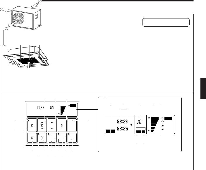
NAME OF PARTS
Instructions relating to heating (*) are applicable only to “HEAT & COOL MODEL” (Reverse Cycle).
Fig. 1 |
Fig. 2 |
Electrical Breaker |
|
|
|
|
|
Fig. 3 |
1 2 3
|
|
|
|
|
|
|
|
|
|
|
This breaker is installed during |
||
|
|
|
|
|
|
|
|
|
|
|
the electrical installation. |
||
Fig. 4 |
|
I |
J |
K |
|
M |
|
|
|
|
|
|
|
|
NON STOP AM |
CLOCK |
|
|
AUTO |
|
N |
O |
|
P |
Q R |
|
|
|
|
|
|
|
|
|
|
|
|
|
|||
|
|
|
°F |
|
|
|
|
|
|
|
|
|
|
H |
TIMER |
SET TIME |
TEMP./DAY |
FAN |
|
L |
NON STOP AMPM CLOCK |
OFF |
|
AUTO |
AUTO |
||
|
OFFON |
|
°F |
|
COOL |
||||||||
MODE |
|
|
CONTROL |
|
|
ON |
|
||||||
|
|
|
|
|
MASTER |
|
TIMER |
AMPM TIMER |
|
FAN |
|||
|
|
|
|
|
|
|
DAY |
|
|||||
|
|
|
|
|
CONTROL |
|
WEEKLY |
|
ON |
|
|||
|
|
|
|
|
|
|
|
DAY OFF |
|
HEAT |
|||
G |
CLOCK ADJUST |
|
|
|
|
|
1 |
2 |
|
OFF |
|
||
|
|
|
|
|
NEXT DAY |
DEFROST TEST |
|
|
|||||
|
|
|
|
|
|
|
|
|
|||||
|
|
|
ZONE |
ENERGY SAVE |
START/STOP |
|
|
|
|
|
|
|
|
SET |
DAY OFF |
S T
Fig. 5 Display
FD B 0 8 6
|
E |
C A 9 7 |
● For explanatory purposes, the figure showing the remote |
||||||||
|
|
|
|
|
|
controller display shows all possible displays. The actual |
|||||
|
|
|
|
|
|
display shows only that area that is being adjusted or used. |
|||||
|
|
|
|
|
|
|
|
|
|
|
|
|
|
|
|
|
|
|
|
|
|
|
|
|
Fig. 1 Indoor Unit |
|
|
|
Fig. 4 Remote Controller |
|
|
|
|
|
|
|
|
|
|
|
|
|
|
|
|||
|
|
|
|
|
|
|
|
|
|
|
|
|
1 Air Filter |
|
|
|
6 START/STOP Button |
K FAN CONTROL Button |
|||||
|
2 Air Intake Grille |
|
|
|
7 Operation Lamp |
|
|
L MASTER CONTROL Button |
|||
|
3 Air Flow Direction |
|
|
|
8 ENERGY SAVE Button |
|
|
|
|
||
|
Flaps |
|
|
|
9 DAY OFF Button |
|
|
|
M Remote Controller Display |
|
|
|
|
|
|
|
|
|
(Fig. 5) |
|
|||
|
|
|
|
|
|
|
|
|
|||
|
|
|
|
|
0 ENERGY SAVE Lamp |
|
|
||||
|
|
|
|
|
|
N Timer Mode Display |
|
||||
|
|
|
|
|
A ZONE Control Button |
|
|
||||
|
Fig. 2 Outdoor Unit |
|
|
|
|
O Clock Display (CLOCK/TIMER) |
|
||||
|
|
|
|
||||||||
|
|
|
|
|
B SET Button |
|
|
|
|
||
|
4 Air intake |
|
|
|
|
|
|
P Set Temperature Display |
|
||
|
|
|
|
C ZONE Control Lamp |
|
|
|||||
|
5 Air outlet |
|
|
|
|
(TEMP.) |
|
||||
|
|
|
|
|
|
|
|
|
|||
|
|
|
|
D AIR FLOW DIRECTION SWING |
|
Q Fan Speed Display |
|
||||
|
|
|
|
|
|
|
|||||
|
|
|
|
|
Button |
|
|
|
|
||
|
|
|
|
|
|
|
|
R Operation Mode Display |
|
||
|
|
|
|
|
E AIR FLOW DIRECTION SWING |
|
|
||||
|
|
|
|
|
|
S DEFROST Display |
|
||||
|
|
|
|
|
Lamp |
|
|
|
|
||
|
|
|
|
|
|
|
|
T TEST Display |
|
||
|
|
|
|
|
F AIR FLOW DIRECTION SET Button |
|
|
||||
|
|
|
|
|
|
|
|
|
|||
|
|
|
|
|
G CLOCK ADJUST Button |
|
|
|
|
||
|
|
|
|
|
|
|
|
|
|||
|
|
|
|
|
H TIMER MODE Button |
|
|
|
|
||
|
|
|
|
|
I SET TIME Button |
|
|
|
|
|
|
|
|
|
|
|
J TEMP./DAY Button |
|
|
|
|
||
|
|
|
|
|
|
|
|
|
|
|
|
En-2

PREPARATION
Set the Current Time and Day
1Press the CLOCK ADJUST button for more than three seconds.
2Press the TEMP./DAY button and set the day.▲: Use to advance the day forward.
▼: Use to turn the day back.
The day is indicated by a code number from 1 to 7, as shown in the table below. Set to the number that corresponds to the current day.
DAY CODE |
1 |
2 |
3 |
4 |
5 |
6 |
7 |
DAY OF THE WEEK |
MON |
TUE |
WED |
THU |
FRI |
SAT |
SUN |
3 |
Press the SET TIME button and set the time. |
▲: Use to advance the time forward. |
|
|
▼: Use to turn the time back. |
|
(Press once to move the time 1 minute; hold down and the time will move |
|
10 minutes at a time.) |
4 |
Press the CLOCK ADJUST button again. |
This registers the new day and time values. The day display goes off, and |
the time display stops flashing.
AM |
CLOCK |
|
|
DAY |
|
TIMER |
SET TIME TEMP./DAY |
FAN |
MODE |
|
CONTROL |
MASTER
CONTROL
CLOCK ADJUST
1 |
ZONE |
ENERGY SAVE START/STOP |
3 |
2 |
|
|
SET |
DAY OFF |
AM CLOCK
Example: Set the time to 9:31.
OPERATION
Instructions relating to heating (*) are applicable only to “HEAT & COOL MODEL” (Reverse Cycle).
To Select Mode Operation
1 |
Press the START/STOP button. |
The unit will start and the remote controller’s operation lamp (green) will |
light up.
2Press the MASTER CONTROL button to select the desired mode.
s |
|
s |
*HEAT |
AUTO |
|
||
COOL |
t |
|
t |
|
|
FAN |
|
To Set the Thermostat
Press the TEMP./DAY button to the desired temperature.
▲ : Press to raise the thermostat setting.
▼: Press to lower the thermostat setting.
●Thermostat setting range:
AUTO ...................................... |
64 to 88 °F |
* Heating ................................... |
60 to 88 °F |
Cooling/Dry ............................ |
64 to 88 °F |
The thermostat cannot be used to set room temperature during the FAN mode (the temperature will not appear on the remote controller’s display).
The thermostat setting should be considered a standard value, and may differ somewhat from the actual room temperature.
NON STOP AM |
CLOCK |
AUTO |
|
|
°F |
|
|
TIMER |
SET TIME TEMP./DAY |
FAN |
|
MODE |
|
CONTROL |
|
|
|
MASTER |
|
|
|
CONTROL |
|
CLOCK ADJUST |
|
|
2 |
|
ZONE |
ENERGY SAVE START/STOP |
|
|
SET |
DAY OFF |
|
Example: When set to AUTO |
1 |
||
|
|||
NON STOP AM |
CLOCK |
AUTO |
|
°F |
|
TIMER |
SET TIME TEMP./DAY |
FAN |
MODE |
|
CONTROL |
|
|
MASTER |
|
|
CONTROL |
CLOCK ADJUST |
|
|
|
ZONE |
ENERGY SAVE START/STOP |
|
SET |
DAY OFF |
Example: When set to 84 °F
En-3
OPERATION
Instructions relating to heating(*) are applicable only to “HEAT & COOL MODEL” (Reverse Cycle).
To Set the Fan Speed
Press the FAN CONTROL button to select the fan speed.
|
|
sAUTO |
sHIGH |
sMED |
|
sLOW |
|
|
|
|
|
|
|||||
When set to AUTO: |
|
|
|
|
|
|||
* Heating |
: Fan operates so as to optimally circulate warmed air. |
|||||||
|
|
However, the fan will operate at very low speed when the tem- |
||||||
|
|
perature of the air issued from the indoor unit is low. |
||||||
Cooling |
: As the room temperature approaches that of the thermostat set- |
|||||||
|
|
ting, the fan speed becomes slower. |
|
|
|
|||
Fan |
: The fan alternately turns on and off; when on, the fan runs at the |
|||||||
|
|
low fan speed. |
|
|
|
|
|
|
The fan will operate at a very low setting during Monitor operation.
NON STOP AM |
CLOCK |
AUTO |
|
°F |
|
TIMER |
SET TIME TEMP./DAY |
FAN |
MODE |
|
CONTROL |
|
|
MASTER |
|
|
CONTROL |
CLOCK ADJUST |
|
|
|
ZONE |
ENERGY SAVE START/STOP |
|
SET |
DAY OFF |
Example: When set to HIGH
 : HIGH
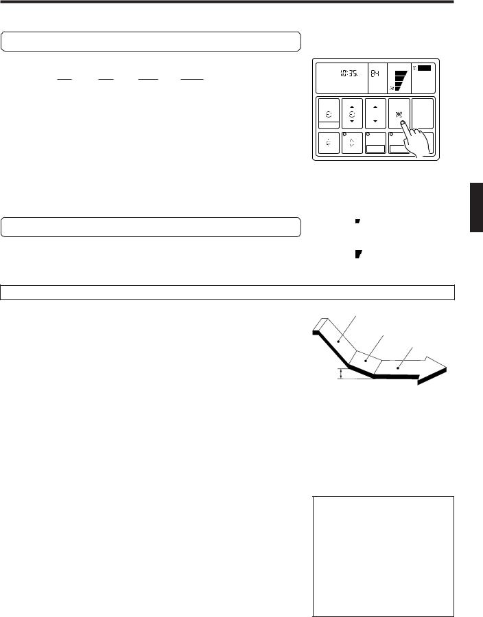
To Stop Operation
Press the START/STOP button.
The remote controller’s operation lamp (green) will go out.
The display contents disappear and only the current time is displayed.
 : MED
: MED
: LOW
About Mode Operation
AUTO:
COOLING MODEL
●When the room temperature is 4 °F higher than the set temperature, the mode will switch between Cooling and Drying.
●During the Drying mode operation, the FAN setting should be switched to LOW for a gently cooling effect during which the fan may temporarily stop rotating.
●If the mode automatically selected by the unit is not satisfactory, see page 3 for instructions on changing the mode setting (COOL, FAN).
AUTO (* AUTO CHANGEOVER):
HEAT & COOL MODEL (Reverse cycle)
Cooling Operation
Dry Operation
Thermostat control
4 °F
Setting temperature
●When AUTO CHANGEOVER is selected, the air conditioner selects the appropriate operation mode (Cooling or Heating) according to your room’s present temperature.
●When AUTO CHANGEOVER is first selected, the fan will operate at very low speed for about one minute while the unit determines the current conditions of the room and accordingly selects the proper operation mode.
●When the air conditioner has adjusted your room’s temperature to near the thermostat setting, it will begin monitor operation. In the monitor operation mode, the fan will operate at low speed. If the room temperature subsequently changes, the air conditioner will once again select the appropriate operation (Heating, Cooling) to adjust the temperature to the value set in the thermostat. (The monitor operation range is ±4 °F relative to the thermostat setting.)
●If the mode automatically selected by the unit is not satisfactory, see page 3 for instructions on changing the mode setting (HEAT, COOL, FAN).
* Heating:
●Use to warm your room.
●When Heating mode is selected, the air conditioner will operate at very low fan speed for about 3 to 5 minutes, after which it will switch to the selected fan setting. This period of time is provided to allow the indoor unit to warm up before begin full operation.
●When the room temperature is very low, frost may form on the outside unit, and its performance may be reduced. In order to remove such frost, the unit will automatically enter the defrost cycle from time to time. During defrosting (see page 15), the heating mode will be temporarily interrupted. DEFROST will be shown on the remote controller display.
Cooling:
● Use to cool your room.
Fan:
● Use to circulate the air throughout your room.
* During Heating mode:
Set the thermostat to a temperature setting that is higher than the current room temperature. The Heating mode will not operate if the thermostat is set lower than the actual room temperature.
During Cooling mode:
Set the thermostat to a temperature setting that is lower than the current room temperature. The Cooling mode will not operate if the thermostat is set higher than the actual room temperature (in Cooling mode, the fan alone will operate).
En-4
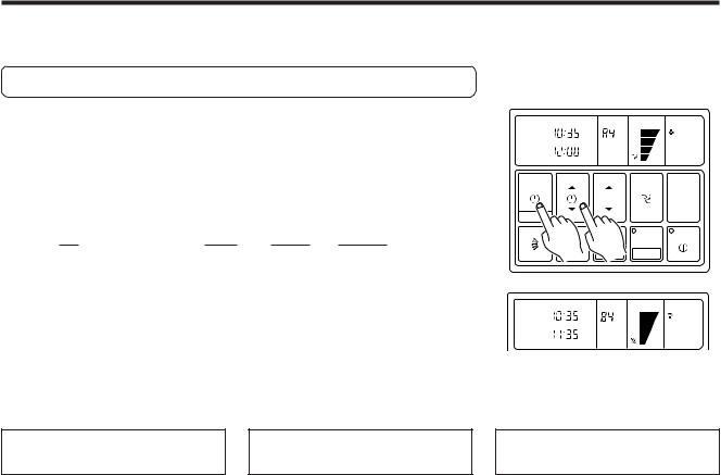
TIMER OPERATION (OFF TIMER/ON TIMER)
Before using the timer function, be sure that the remote controller is set to the correct current time and Day. Press the START/STOP button; after the unit starts operation perform the following procedure:
OFF Timer / ON Timer
1Press the TIMER MODE button and display either OFF Timer or ON Timer.
The timer will start operating. (If you set the ON timer, the air conditioner will stop operating).
Each time the button is pressed the timer function changes in the following order:
|
sNON STOP (RESET) |
sOFF |
sON |
sWEEKLY |
|
|
|
||||
|
|
|
|
|
|
2Press the SET TIME button and set the timer time.
▲ : Use to advance the time forward. ▼ : Use to turn the time back.
(Press once to move the time 1 minute; hold down and the time will move 10 minutes at a time.)
|
AM |
CLOCK |
|
|
OFF |
|
|
°F |
COOL |
TIMER |
AM |
TIMER |
|
|
|
|
|||
|
|
OFF |
|
|
TIMER |
|
SET TIME |
TEMP./DAY |
FAN |
MODE |
|
|
|
CONTROL |
|
|
|
|
MASTER |
|
|
|
|
CONTROL |
CLOCK ADJUST |
|
|
|
|
|
|
1 |
2 |
ENERGY SAVE START/STOP |
|
|
|
ZONE |
|
|
|
|
SET |
DAY OFF |
AM |
CLOCK |
|
|
|
OFF |
|
|
°F |
COOL |
TIMER |
PM TIMER |
|
||
|
|
|||
|
|
OFF |
|
|
TIMER |
|
SET TIME |
TEMP./DAY |
FAN |
Example: |
Setting the OFF TIMER |
|||
MODE |
|
|
|
CON ROL |
to 11:35 p.m. |
MASTER |
CONTROL |
|
|
|
CLOCK ADJUST |
|
To confirm or Change Settings Before Starting Operation
●To confirm settings
Press the TIMER MODE button once. (The timer setting information will be displayed for 15 seconds after the TIMER MODE button is pressed.)
●To change settings
Confirm the settings as noted above, then press the SET TIME button and TIMER MODE button as necessary to change the desired timer setting. (The timer settings will be displayed for 15 seconds after the button is pressed.)
●After confirming or changing the settings, press the START/STOP button to start operation.
To Change the Timer Setting
During Operation
Operate as noted in step 2.
ZONE |
ENERGY SAVE START/STOP |
SET |
DAY OFF |
To Cancel the Timer Mode |
|
During Timer Operation |
|
Press the TIMER MODE button and set the display to “NON STOP” (the unit will switch to non-stop operation).
To Change the Timer Mode |
|
To Stop Operation During |
During Operation |
|
Use of Timer Mode |
|
|
|
Press the TIMER MODE button and set |
Press the START/STOP button. |
|
the unit to the desired mode. |
|
|
En-5
 Loading...