

Page 1
USER GUIDE
Page 2

Manufacturer
FUJIFILM SonoSite, Inc.
21919 30th Drive SE
Bothell, WA 98021 USA
T: 1-888-482-9449 or 1-425-951-1200
F: 1-425-951-1201
EC Authorized Representative
FUJIFILM SonoSite B.V.
Joop Geesinkweg 140
1114 AB Amsterdam,
The Netherlands
Australia Sponsor
FUJIFILM SonoSite Australasia Pty Ltd
114 Old Pittwater Road
BROOKVALE, NSW, 2100
Australia
Caution
Federal (United States) law restricts this device to sale by or on the order
of a physician.
iViz, Sonosite, and the Sonosite logo are trademarks and registered trademarks of FUJIFILM Sonosite, Inc. in various jurisdictions.
FUJIFILM is a trademark and registered trademark of FUJIFILM Corporation in various jurisdictions.
Dicom is a registered trademark of the National Electrical Manufacturers Association.
All other trademarks are the property of their respective owners.
Part Number: P20016-05
Publication Date: November 2017
Copyright © 2017 FUJIFILM SonoSite, Inc. All rights reserved.
Page 3

Chapter 1: Introduction
About the SonoSite iViz User Guide ............................................................................................................ 1
Document conventions ..........................................................................................................................1
Getting help ................................................................................................................................................ 2
Chapter 2: Getting Started
About SonoSite iViz ........................................................................................................................................... 3
Intended use ........................................................................................................................................................ 3
Diagnostic ultrasound ............................................................................................................................. 3
Contraindications ......................................................................................................................................4
Accessories and peripherals ........................................................................................................................... 4
Hardware features ..............................................................................................................................................5
General interaction ............................................................................................................................................7
Using the touchscreen ............................................................................................................................ 7
Using gestures ............................................................................................................................................ 9
Using the control wheel .........................................................................................................................9
Opening menus and tool drawers ....................................................................................................10
Entering text .............................................................................................................................................11
Put the system into the protective case ...................................................................................................11
Plugging in a transducer ...............................................................................................................................12
Installing the battery and charging SonoSite iViz ................................................................................12
Installing the battery .............................................................................................................................12
Charging the battery .............................................................................................................................13
Removing the battery ...........................................................................................................................15
Turning SonoSite iViz on and off ................................................................................................................15
Turning on SonoSite iViz ......................................................................................................................16
Turning off SonoSite iViz ......................................................................................................................16
Putting the system into sleep mode ................................................................................................16
Chapter 3: Configuring SonoSite iViz
Configuring Android settings ......................................................................................................................17
CONTENTS
Activating security settings .................................................................................................................17
Connecting to a wireless network ....................................................................................................17
Connecting to a virtual private network (VPN) ............................................................................18
Connecting to a Bluetooth device ....................................................................................................18
Setting the date and time ....................................................................................................................19
iii
Page 4

Adjusting the volume ............................................................................................................................19
Adjusting the screen brightness .......................................................................................................20
Configuring sleep mode .......................................................................................................................20
Adding a wireless printer .....................................................................................................................21
Configuring SonoSite iViz settings ............................................................................................................21
Opening the SonoSite iViz Settings screen ...................................................................................22
Configuring preferences .......................................................................................................................22
Configuring OB measurements and calculations ........................................................................24
Configuring labels ..................................................................................................................................24
Setting up a DICOM profile ..................................................................................................................25
Configuring patient search settings .................................................................................................27
Configuring EMR settings and preferences ...................................................................................28
Connecting to a separate display ...............................................................................................................28
Chapter 4: Managing Patient Records
About SonoSite iViz studies ..........................................................................................................................31
Accessing patient information ....................................................................................................................31
Searching for a patient record ............................................................................................................31
Managing studies .............................................................................................................................................33
Viewing scheduled studies ..................................................................................................................33
Browsing and viewing scheduled studies ......................................................................................33
Creating or updating a patient study ..............................................................................................34
Ending a study .........................................................................................................................................35
Sharing a study ........................................................................................................................................36
Managing reports ............................................................................................................................................36
Editing a report ........................................................................................................................................37
Printing a report ......................................................................................................................................37
Sharing a report .......................................................................................................................................38
Chapter 5: Performing an Exam
Understanding optimal thermal performance ......................................................................................39
Beginning an exam ..........................................................................................................................................39
Understanding imaging modes ..................................................................................................................40
CONTENTS
Exam overview .........................................................................................................................................41
Choosing a transducer and exam type ...........................................................................................42
Reviewing patient information ..........................................................................................................44
Scanning in 2D ..................................................................................................................................................44
Scanning in color ....................................................................................................................................44
iv
Page 5

Switching between CVD and CPD ....................................................................................................47
Controlling color gain ............................................................................................................................47
Adjusting scale .........................................................................................................................................48
Inverting the blood flow colors .........................................................................................................49
Filtering .......................................................................................................................................................49
Controlling flow .......................................................................................................................................50
Scanning in M Mode .......................................................................................................................................50
Moving the M Line ..................................................................................................................................51
Updating in M Mode .......................................................................................................................................51
Changing the sweep speed .................................................................................................................51
Setting the image orientation .....................................................................................................................52
Optimizing the image ....................................................................................................................................53
Adjusting depth and gain .............................................................................................................................54
Adjusting depth .......................................................................................................................................54
Adjusting gain ..........................................................................................................................................55
Controlling the dynamic range ...................................................................................................................56
Accessing guided protocols .........................................................................................................................57
Physical .......................................................................................................................................................57
eFAST ...........................................................................................................................................................58
FATE ..............................................................................................................................................................58
RUSH ............................................................................................................................................................59
Chapter 6: Managing Images and Clips
Freezing an image ............................................................................................................................................61
Saving an image or a clip ..............................................................................................................................62
Reviewing an image or clip ..........................................................................................................................63
Zooming in and out of an image ......................................................................................................63
Adding labels .....................................................................................................................................................63
Deleting images and clips .............................................................................................................................65
Sending and sharing images and clips ....................................................................................................65
Chapter 7: Measurements and Calculations
Taking measurements ....................................................................................................................................67
CONTENTS
Working with calipers ............................................................................................................................67
Viewing and deleting measurement results .................................................................................68
Taking basic measurements ...............................................................................................................68
About calculations ...........................................................................................................................................71
Overview ....................................................................................................................................................71
v
Page 6

Calculating volume ................................................................................................................................72
Exam-based calculations ...............................................................................................................................74
Cardiac calculations ...............................................................................................................................74
Obstetrics calculations ..........................................................................................................................76
Abdomen, breast, lung, MSK, and nerve calculations ...............................................................79
Chapter 8: Measurement References
Measurement accuracy ..................................................................................................................................81
Measurement publications and terminology ...............................................................................82
Chapter 9: Troubleshooting and Maintenance
Troubleshooting ...............................................................................................................................................93
Common problems ................................................................................................................................93
Understanding error messages. .........................................................................................................93
Troubleshooting connectivity problems ........................................................................................96
DICOM common problems ..................................................................................................................96
Maintenance ......................................................................................................................................................98
Upgrading SonoSite iViz software and firmware ........................................................................98
iViz performance testing ...............................................................................................................................99
Overview ....................................................................................................................................................99
Recommended test equipment ........................................................................................................99
Functional acceptance ..........................................................................................................................99
2D performance tests ......................................................................................................................... 100
Additional performance tests ..........................................................................................................102
M Mode imaging ..................................................................................................................................103
Chapter 10: Cleaning and Disinfecting
Before getting started .................................................................................................................................105
Determining the required cleaning and disinfection level ............................................................107
Spaulding classifications ................................................................................................................... 107
CONTENTS
Clean and disinfect system and transducer to a high level (semi-critical uses) ............ 107
Clean and disinfect system and transducer to a low level (non-critical uses) ................ 114
Cleaning the iViz carry case ....................................................................................................................... 120
Storing the transducer ................................................................................................................................ 120
Transporting the transducer ..................................................................................................................... 120
Disposing of the system .............................................................................................................................122
vi
Page 7

Chapter 11: Safety
Ergonomic safety ........................................................................................................................................... 123
Minimize eye and neck strain .......................................................................................................... 124
Support your back during an exam .............................................................................................. 124
Minimize reaching and twisting .....................................................................................................124
Promote comfortable shoulder and arm postures .................................................................. 124
Employ comfortable postures ......................................................................................................... 124
Use comfortable wrist and finger postures with transducers .............................................. 125
Take breaks, exercise, and vary activities ..................................................................................... 125
System and transducer temperatures ................................................................................................... 126
Electrical safety ..............................................................................................................................................126
Electrical safety classification .......................................................................................................... 128
Equipment safety .......................................................................................................................................... 128
Battery safety .................................................................................................................................................. 129
Clinical safety .................................................................................................................................................. 131
Hazardous materials .....................................................................................................................................131
Electromagnetic compatibility ................................................................................................................. 132
Wireless transmission ......................................................................................................................... 133
Electrostatic discharge ....................................................................................................................... 134
Separation distance ............................................................................................................................ 134
Compatible accessories and peripherals .....................................................................................135
Guidance and manufacturer’s declaration ................................................................................. 136
labeling symbols .......................................................................................................................................... 143
Specifications .................................................................................................................................................. 145
Dimensions ............................................................................................................................................ 145
Environmental limits ........................................................................................................................... 146
Electrical specifications ......................................................................................................................146
Battery specifications ......................................................................................................................... 146
Equipment specifications ..................................................................................................................147
Standards .........................................................................................................................................................147
Electrical safety standards ................................................................................................................ 147
EMC standards classification ............................................................................................................ 147
Acoustic standards .............................................................................................................................. 148
Biocompatibility standards .............................................................................................................. 148
CONTENTS
Airborne equipment standards ...................................................................................................... 148
DICOM standard ...................................................................................................................................148
Security and privacy standards ....................................................................................................... 148
Wireless standards ............................................................................................................................... 148
vii
Page 8

Chapter 12: Acoustic Output
ALARA principle ............................................................................................................................................. 151
Applying the ALARA principle ......................................................................................................... 151
Direct, indirect, and receiver controls ........................................................................................... 152
Acoustic artifacts ........................................................................................................................................... 152
Guidelines for reducing MI and TI ...........................................................................................................153
Output display ................................................................................................................................................ 154
MI and TI output display accuracy ................................................................................................. 154
Factors that contribute to display uncertainty ..........................................................................154
Related guidance documents ......................................................................................................... 155
Transducer surface temperature rise ..................................................................................................... 155
Acoustic output measurement ................................................................................................................ 156
Tissue models and equipment survey .......................................................................................... 157
Acoustic output tables ................................................................................................................................ 158
Acoustic measurement precision and uncertainty ..................................................................163
Terminology in acoustic output tables ........................................................................................ 163
Glossary ............................................................................................................................................................ 165
General terms ........................................................................................................................................ 165
Chapter 13: IT Network
Functions ..........................................................................................................................................................167
Network for connecting the device ........................................................................................................167
Specifications for the connection ........................................................................................................... 167
Hardware specification ...................................................................................................................... 167
Software specifications ...................................................................................................................... 167
Security .................................................................................................................................................... 167
Data flow ................................................................................................................................................. 168
IT network failure recovery measures .................................................................................................... 169
CONTENTS
viii
Page 9

Chapter 1: Introduction
About the SonoSite iViz User Guide
The SonoSite iViz User Guide provides information about configuring and using the SonoSite iViz ultrasound
system, including:
Managing patient data
Performing exams
Taking measurements and calculations
Cleaning and disinfecting
The information and procedures in this user guide apply to the SonoSite iViz system and its included
accessories. Other accessories and third-party equipment are subject to their own instructions and
restrictions.
The SonoSite iViz User Guide is intended for a user familiar with ultrasound. It does not provide training in
sonography, ultrasound, or clinical practices. Before using SonoSite iViz, you must complete such training.
Document conventions
The document follows these conventions:
A
WARNING describes precautions necessary to prevent injury or loss of life.
A
Caution describes precautions necessary to protect the products.
A
Note provides supplemental information.
Numbered and lettered steps must be performed in a specific order.
Single-step procedures begin with this symbol:
Bulleted lists present information in list format but do not imply a sequence.
About the SonoSite iViz User Guide 1
Page 10

Getting help
In addition to this user guide, the following resources are available:
Instructional videos
On-board help videos
FUJIFILM SonoSite Technical Support:
Phone
(U.S. or Canada)
Phone
(outside U.S. or Canada)
Fax 425-951-6700
Email ffss-service@fujifilm.com
Web www.sonosite.com
Europe Service Center Main: +31 20 751 2020
Asia Service Center +65 6380-5581
877-657-8118
425-951-1330, or call your local representative
English support: +44 14 6234 1151
French support: +33 1 8288 0702
German support: +49 69 8088 4030
Italian support: +39 02 9475 3655
Spanish support: +34 91 123 8451
2 About the SonoSite iViz User Guide
Page 11

Chapter 2: Getting Started
Use this section to help familiarize yourself with the SonoSite iViz system and its uses.
About SonoSite iViz
SonoSite iViz is a portable, hand-held device that acquires and displays high-resolution, real-time ultrasound
images. Features available on the system include:
2D scanning mode with color Doppler
Measurement and calculation support
Image labeling
DICOM support
EMR system integration
On-board help videos
Intended use
Diagnostic ultrasound
The SonoSite iViz Ultrasound System is a general purpose ultrasound system and non-continuous patient
monitoring platform intended for use in clinical care by qualified physicians and healthcare professionals for
evaluation by ultrasound imaging and fluid flow analysis.
In the ultrasound scanning application, the SonoSite iViz system with an attached transducer obtains
ultrasound images as described below:
Abdominal imaging applications are designed to assess the liver, kidneys, pancreas, spleen, gallbladder,
bile ducts, transplanted organs, abdominal vessels, and surrounding anatomical structures for the
presence or absence of pathology transabdominally. Abdominal imaging can be used to evaluate the
presence or absence of blood flow in abdominal organs.
Cardiac imaging applications are designed to assess the pericardial effusion or cardiac tamponade
possibility, cardiac valves, the great vessels, heart size, cardiac function, lung, and surrounding
anatomical structures for the presence or absence of pathology.
Obstetrical imaging applications are designed to assess the fetal anatomy, viability, estimated fetal
weight, fetal heart rate, fetal position, gestational age, amniotic fluid, and surrounding anatomical
structures for the presence or absence of pathology transabdominally.
About SonoSite iViz 3
Page 12

Color Power Doppler (CPD) and Color Velocity Doppler (CVD) imaging tools are intended to evaluate the
blood flow of the fetus, placenta, umbilical cord, and surrounding maternal structures in all cases,
including high-risk pregnancies. High-risk pregnancy indications include, but are not limited to,
multiple pregnancies, fetal hydrops, placental abnormalities, maternal hypertension, diabetes, and
lupus.
CPD and color imaging tools are not intended as a sole means of diagnosis nor as a sole method of high-
risk pregnancy screening.
Superficial imaging applications are designed to assess the breast, thyroid, testicle, lymph nodes,
nerves, hernias, musculoskeletal structures, soft tissue structures, and surrounding anatomical
structures for the presence or absence of pathology.
Vascular imaging applications are designed to assess the carotid arteries, deep veins, and arteries in the
arms and legs, superficial veins in the arms and legs, great vessels in the abdomen, and various small
vessels feeding organs for the presence or absence of pathology.
Contraindications
SonoSite iViz is not intended for opthalmic use or any application that causes the acoustic beam to pass
through the eye.
Accessories and peripherals
Caution
The SonoSite iViz ultrasound system is designed to support a variety of accessories and peripherals, including:
2-in-1 micro USB flash drive (64 GB)
Protective case with handle and kickstand
SonoSite iViz carry case
Pelican case
SonoSite iViz batteries
USB charger
Battery bay charger with power supply
Dual charging station
Use only accessories and peripherals recommended by FUJIFILM SonoSite, including
the power supply. Connection of accessories and peripherals not recommended by
FUJIFILM SonoSite could result in electrical shock. Contact FUJIFILM SonoSite or
your local representative for a list of accessories and peripherals available from or
recommended by FUJIFILM SonoSite.
4 Accessories and peripherals
Page 13
To order accessories, or to find out if a specific piece of equipment is compatible with the SonoSite iViz
ultrasound system, contact FUJIFILM SonoSite or your FUJIFILM SonoSite representative. See “Getting help”
on page 2.
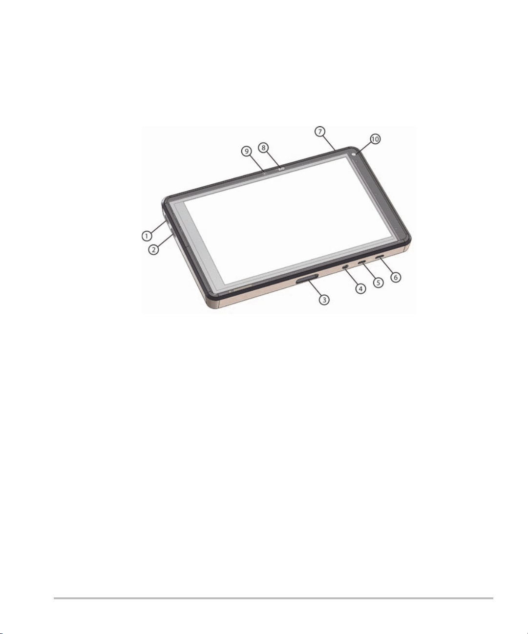
Hardware features
The front of the system is shown in Figure 2-1.
Figure 2-1 Front of the SonoSite iViz ultrasound system
1
Volume up 6 Micro USB port
2
Volume down 7 Power on/off
3
Transducer socket 8 Power status LED
4
Audio out 9 Microphone
5
Micro HDMI port 10 Front camera
Hardware features 5
Page 14
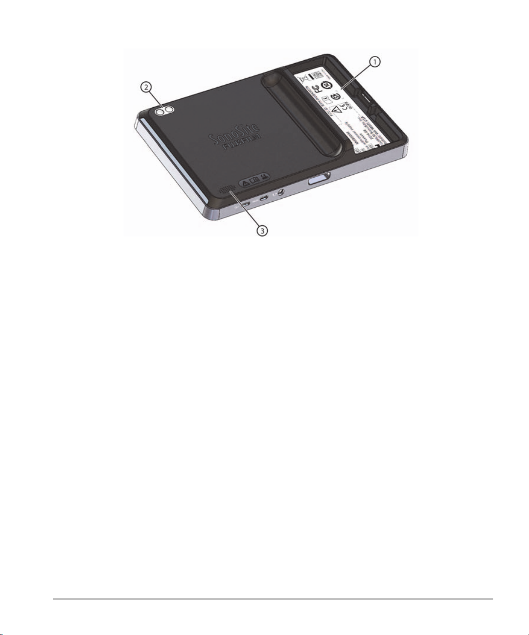
The back of the system is shown in Figure 2-2.
Figure 2-2 Back of the SonoSite iViz ultrasound system
1Battery bay 3Speaker
2 Camera and flash
6 Hardware features
Page 15
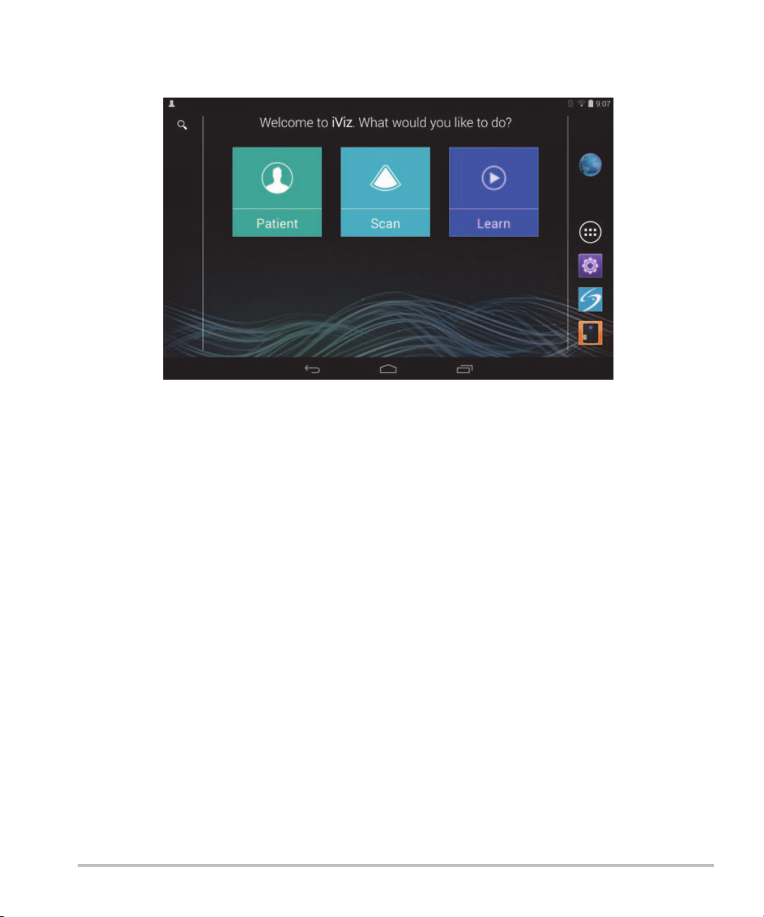
General interaction
When you first turn on SonoSite iViz, the Home screen displays, as shown in Figure 2-3.
Figure 2-3 SonoSite iViz Home screen
The system has three main modules that are accessible from the Home screen: Patient, Scan, and Learn.
Patient - This module lets you search for a patient, view the scheduled list of patients, and select a SonoSite
iViz study. In addition, you can add and edit a patient form and view and share images and clips.
Scan - This module is where you perform patient exams.
Learn - This module contains general ultrasound training videos and SonoSite iViz on-board help videos.
Using the touchscreen
When scanning, the SonoSite iViz touchscreen is divided into two main areas: the left side contains your
controls, and the right side is the scan area, as shown in Figure 2-4.
General interaction 7
Page 16
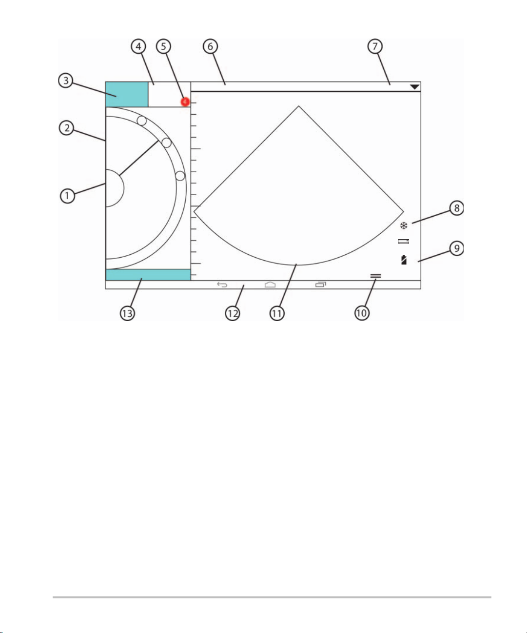
Figure 2-4 Touchscreen while in scan mode
FREEZE SAVE
Patient: John Smith
ID: 1234567890
P21v: Abdomen
End Study
2D
C
COLOR
Orient
Dynamic
Range
Opt
Depth: 16.4cm
89%
13%
09:15
01/01/2015
MI:
0.0
TI:
0.0
DR:
0
Pen
MHz
0.00
RES
PEN
THI
1 Scan mode selector 8 Power management indicator: flashing white -
Slow frame rate mode. Solid blue - Freeze
mode.
2 Thumb-operated control wheel 9 Time, date, and percent charged
3 Freeze an image 10 Tool drawer handle
4 Capture an image or a clip 11 Scan area
5 Number of saved images and clips in this study 12 Android controls
6 Patient name and data (tap to go to Patient
module)
7Type of exam
The system is designed so that you can use one hand to hold the system and the other hand to hold the
13 End the study and return to patient record
transducer. If you’re not scanning, you can always use two hands.
8 General interaction
Page 17
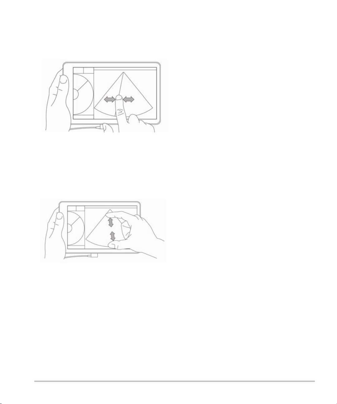
Using gestures
You interact with the touchscreen the same as with many other touchscreen devices:
Swipe - Move your finger quickly across the screen.
Drag - Move one or two fingers across the screen, usually to move an object from one location to another.
Tap - Quickly touch the screen once.
Press and hold - Touch your finger to the screen, and hold it there for about two seconds.
Pinch or zoom - Slide two fingers together or apart on the screen.
The controls that appear on the wheel depend on the scan mode you've selected. The function of each control
is discussed in detail in Chapter 5, “Performing an Exam.”
Using the control wheel
In scanning mode, use the control wheel to scroll through the available controls.
General interaction 9
Page 18

Opening menus and tool drawers
You can access additional controls by opening menus and tool drawers.
This symbol indicates a drop-down menu. Tap or swipe down on this symbol to open the menu. For
instance, the Exam Type menu allows you to choose between several preset exam types.
This symbol indicates a drawer that you can open. Swipe up on this symbol to open the tool drawer.
The tool drawer contains additional options such as labels, measurements, and guided protocols.
This symbol indicates the drawer that opens the cine buffer when you are taking measurements or
adding labels. Slide the drawer to the right to display the cine buffer, and slide it to the left to close it.
10 General interaction
Page 19
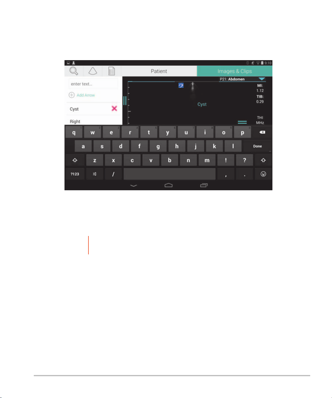
Entering text
When filling out forms in SonoSite iViz, such as when you are updating patient records or configuring settings,
you can enter text by tapping the text field you want to edit. An on-screen keyboard appears, as shown in
Figure 2-5.
Figure 2-5 Use the keyboard to type information.
Put the system into the protective case
Caution
To put the system into the protective case
1 Insert the system into one end of the case.
2 Bring the opposite case end over the system to hold it in place.
SonoSite iViz device emits RF emissions. While the system meets SAR standards,
using the protective case is recommended to reduce RF exposure.
Put the system into the protective case 11
Page 20

Plugging in a transducer
Insert the transducer connector into the bottom of the SonoSite iViz system, with the transducer cable
facing away from the other connectors, until you hear it click.
Installing the battery and charging SonoSite iViz
Installing the battery
Note Battery performance depends on numerous factors, such as the scanning modes
used, battery age, and display brightness.
To install the battery
WARNING
1 On the back of the SonoSite iViz system, position the battery in the battery slot so that the beveled edge of
the battery is nearest the side of the SonoSite iViz system.
2 Press the battery firmly into the back of the SonoSite iViz system until it locks in place.
12 Plugging in a transducer
To avoid injury to the operator and to prevent damage to the ultrasound system,
inspect the battery for leaks before installing.
Page 21

Charging the battery
WAR NIN G:
Cautions
There are two ways to charge the SonoSite iViz batteries; you can use the included battery charger or plug in
the USB charger while a battery is installed in system.
To avoid the risk of electrical shock, burn, or fire, use only the FUJIFILM SonoSite USB
charger (P19927).
The battery can be stored at temperatures between -20°C (-4°F) to 60°C (140°F).
Charge batteries only when the ambient temperature is between 10°C (50°F) and
40°C (104°F).
SonoSite iViz will not operate without a battery installed, even if the USB charger is
plugged in.
Verify that the hospital supply voltage corresponds to the power supply voltage
range. See “Electrical safety standards” on page 147.
When the battery charge is low on your SonoSite iViz system, you have the option
of plugging the system in to recharge, or replacing the battery with a freshly
charged one.
To avoid risk from loss of power, plug the system into an appropriate power source
or change batteries when the battery is low.
To charge the battery while it’s installed in the SonoSite iViz system
1 Turn off the system. See “Turning off SonoSite iViz” on page 16.
2 Connect the line cord of the AC power adapter to a hospital-grade electrical outlet.
Installing the battery and charging SonoSite iViz 13
Page 22

3 Connect the AC power adapter to the micro-USB power receptacle on the system.
Notes SonoSite iViz cannot perform scanning functions while the AC power adapter is
attached to the system.
Charging the battery this way may require more time than when using the battery
charger.
SonoSite iViz is not provided with an AC mains power switch. To disconnect the
equipment from the mains, unplug the AC power adapter from the wall outlet and
the system.
4 When you are finished charging the battery, disconnect the system from AC power.
5 Turn the system on to check the battery charge.
To charge the battery using the SonoSite iViz battery charger
1 Connect the line cord of the AC power adapter to a hospital-grade electrical outlet.
2 Connect the AC power adapter to the receptacle on the battery charger.
3 Remove the battery from the SonoSite iViz system, and insert it in a slot on the battery charger. You can
charge up to two batteries at a time.
Note The optional SonoSite iViz dual charging station allows you to charge two batteries
at a time. Using an optional kit, you can join two charging stations together to
provide even more charging capacity.
14 Installing the battery and charging SonoSite iViz
Page 23

4 To determine battery charging status, check the lights on the battery charger:
Blinking green Battery is charging.
Green Battery is fully charged.
Amber/light red Battery is very low.
If the light does not change to blinking or steady green after
three hours, try the following:Remove and re-insert the
battery.
Unplug the battery charger, and then plug it back in.
Red Bad battery pack; recycle the battery.
Caution
If the light on the battery charger remains amber/light red for more than three hours,
even after multiple charging attempts, the battery may be faulty. Do not use the
battery in the SonoSite iViz system. Do not try to repair the battery. Remove the
battery from the charger, and then contact FUJIFILM SonoSite or your representative
to get a replacement. Recycle or dispose of faulty batteries in accordance with
applicable laws.
Removing the battery
To remove the battery
1 Turn off the system. See “Turning off SonoSite iViz” on page 16.
2 On the back of the SonoSite iViz system, press the battery lock in to unlock the battery.
3 Pull up the battery to remove it.
Turning SonoSite iViz on and off
The system is battery powered.
WAR NIN G
Do not use the system if it exhibits erratic or inconsistent behavior. Such behavior
indicates a hardware failure. Contact FUJIFILM SonoSite Technical Support.
Caution:
Turning SonoSite iViz on and off 15
The battery should be charged before installing in the SonoSite iViz system for the
first time. For more information, see “Charging the battery” on page 13.
Page 24

Turning on SonoSite iViz
To turn on SonoSite iViz
1 Check that a battery is installed in the SonoSite iViz system. For more information, see “Installing the
battery” on page 12.
2 Press the Power button, and wait several seconds for the system to power on.
The white light indicates that the system is powering up.
3 Swipe up on the Lock icon.
The SonoSite iViz Home screen appears.
Turning off SonoSite iViz
To turn off SonoSite iViz
1 Press and hold the Power button.
2 When prompted, tap Power off, and then OK.
Caution
To avoid data loss, wait for the system’s “power off” message before removing the
battery from the system.
Putting the system into sleep mode
To conserve battery power, the system enters sleep mode after a period of inactivity, typically about 30
seconds. You can change the length of time before it goes into sleep mode; see “Configuring sleep mode”
on page 20.
Sleep mode turns off the display but holds the current functions in memory so that they can be recalled
quickly when the system is awakened. Sleep mode is disabled during scanning.
Caution
To put the system into sleep mode
Briefly press the Power button.
If the system is in sleep mode, briefly press the Power button to wake it up; the
display does not indicate activity when SonoSite iViz is asleep.
16 Turning SonoSite iViz on and off
Page 25

Chapter 3: Configuring SonoSite iViz
Configuring Android settings
Google Android is the operating system (OS) that the SonoSite iViz software runs on. The Android OS manages
and monitors things like wireless connectivity, date and time, and battery charge. Most Android settings will
be pre-configured by FUJIFILM SonoSite, but there are several Android functions that you can configure
yourself.
To open the Android Settings screen
1 Tap to open the Home screen.
2 From the Home screen, tap to open the Apps menu.
3 From the Apps menu, tap Settings.
Activating security settings
For patient data privacy and security, FUJIFILM SonoSite recommends that you activate a PIN, password, or
pattern from the Security screen. If applicable, talk to your IT Administrator.
Connecting to a wireless network
Before trying to connect to a wireless network, you must gather the following information:
The name of the wireless network you want to join
The security password, if any, for the wireless network
To connect to a wireless network
1 From the Android Settings screen, slide the Wi-Fi button to ON (if Wi-Fi is not already enabled).
2 Tap Wi-Fi, and tap the wireless network you want to join.
3 Type the password for the wireless network, and then tap Done.
4 Tap Connect.
5 From the Wi-Fi screen, check that the word Connected appears under the wireless network you chose.
If the connection was not successful, check that you have the right password, and try again.
Configuring Android settings 17
Page 26

Connecting to a virtual private network (VPN)
Note For security reasons, your SonoSite iViz system must be secured with some form of
password before you can connect to a VPN. For more information, see “Activating
security settings” on page 17.
Before trying to connect to a VPN, you must gather the following information:
The name of the VPN.
The type of VPN, including any specialized settings.
Your VPN credentials, including your user name and password.
To connect to a VPN
1 From the Android Settings screen, under Wireless & Networks, tap More.
2 Tap VPN.
3 On the VPN screen, tap .
4 Enter your VPN profile information, including the name of the VPN, the VPN type, and any additional
settings.
5 Tap Save.
6 Log in to the VPN using your VPN user name and password.
To enable future VPN connections, check the Save account information check box.
7 To add another VPN, tap + and repeat steps 4-6.
Connecting to a Bluetooth device
1 From the Android Settings screen, tap Bluetooth.
2 From the Bluetooth screen, slide the Bluetooth button to ON (if Bluetooth is not already enabled).
3 If necessary, place the target device in pairing mode.
4 From the Bluetooth screen, tap the Bluetooth device you want to connect to.
5 Confirm the Bluetooth pairing on both devices.
18 Configuring Android settings
Page 27

Setting the date and time
WAR NIN G
To manually set the date and time
By default, the SonoSite iViz system date and time are set automatically when you connect to a wireless
network. If you choose not to connect your SonoSite iViz system to a network, or if you want to use a different
date and time, use the following manual procedure.
1 From the Android Settings screen, tap Date & Time.
2 From the Date & Time screen, clear the check box for Automatic date & time.
3 Tap Set date, choose the date you want to set, and then tap Done.
4 Tap Set time, choose the time you want to set, and then tap Done.
To manually set the time format
You can switch between the 24-hour clock format and the 12-hour clock format.
1 From the Android Settings screen, tap Date & Time.
2 To select the 24-hour clock mode, on the Date &Time screen, select the check box next to Use 24-hour
format.
To obtain accurate calculations, an exact date and time are critical. Verify that the
date and time are accurate before each use of the system.
3 To select the 12-hour clock mode, on the Date & Time screen, clear the check box next to Use 24-hour
format.
To manually set the date format
By default, the date format is set to <month>/<day>/<year>. This is not the standard in all areas, however. To
change the way SonoSite iViz presents date information, do the following:
1 From the Android Settings screen, tap Choose date format.
2 Tap the radio button next to the date format you want to use.
Adjusting the volume
To adjust the volume
1 From the Android Settings screen, tap Sound.
Configuring Android settings 19
Page 28

2 From the Sound screen, tap Volum es.
3 Adjust the sliders to the volume levels you want, and then tap OK.
Adjusting the screen brightness
To manually adjust the screen brightness
1 From the Android Settings screen, tap Display.
2 From the Display screen, tap Brightness.
3 If auto mode is highlighted, tap Auto to adjust the brightness manually.
4 Move the slider to set the brightness.
Configuring sleep mode
Changing the sleep mode interval
During periods of inactivity, iViz automatically switches to sleep mode to preserve battery life and prevent
overheating.
By default, when not in scanning mode, SonoSite iViz goes to sleep as described in the section “To change
the Android sleep mode interval (non-scanning mode)” on page 20. When scanning, SonoSite iViz will
go into Slow frame rate mode, then auto freeze, then sleep, and finally power off as described in
“Configuring preferences” on page 22.
If you move the transducer during the Slow frame rate mode, SonoSite iViz returns to normal operation;
however, once the image is frozen, you will have to manually unfreeze it.
You can manually change both of these intervals to suit your preferences
To change the Android sleep mode interval (non-scanning mode)
1 From the Android Settings screen, tap Display.
2 From the Display screen, tap Sleep.
3 Tap the time period you want to change to. This is the period of inactivity before the system switches to
sleep mode.
Understanding sleep mode and screen lock settings
If the system is unlocked and not in scanning mode, SonoSite iViz goes into sleep mode as described in the
section “To change the Android sleep mode interval (non-scanning mode)” on page 20.
20 Configuring Android settings
Page 29

If the system is locked:
if the Android settings under Security > Screen lock are set to anything other than None, after the
system reboots or the system wakes from sleep mode, the system must be first be unlocked before
using it.
If you do not unlock the system, it returns to sleep mode in 10 seconds.
Adding a wireless printer
With the PrintHand app, you can connect to a wireless printer. Before adding a printer, make sure the Android
Wi-Fi feature is turned on; see “Connecting to a wireless network” on page 17.
To add a wireless printer
1 From the Android Settings screen, tap Printing.
2 From the Printing screen, tap PrintHand.
3 In the upper right corner of the screen, tap the OFF button.
4 At the Use PrintHand prompt, tap OK.
5 In the upper right corner of the screen, tap the three dots, and then tap Add a printer.
6 From the Nearby Printers menu, tap one of the options, such as Nearby Wi-Fi Printers. SonoSite iViz
searches for a wireless printer.
7 Tap the printer you want to add.
8 From the Driver Needed screen, tap Select Manually, and tap Next. You can also tap Generic to select a
generic driver; however, you will have more print options if you select the driver for your specific printer.
9 Tap through the options to find the driver for your printer brand and model.
10 Tap Install.
11 When prompted to do a print test, tap Print Test (optional).
12 When you are done, click Finish.
Configuring SonoSite iViz settings
SonoSite iViz can be adapted to a wide variety of conditions. For example, from the SonoSite iViz Settings
screen, you can:
Configuring SonoSite iViz settings 21
Page 30

Set user preferences, such as units of measure, right or left-handed operation, standard clip length and
type.
Customize the obstetrics tools the system uses to help you calculate gestational age.
Add to or change the standard labels available in various exam types.
Set up or change DICOM profiles for each unique location/institution and connect to the local servers.
Modify patient search parameters, such as name, ID, date of birth, and procedure.
Specify EMR connection settings, such as host name, IP address, and port.
Opening the SonoSite iViz Settings screen
To open the Settings screen
From the SonoSite iViz Home screen, tap Settings .
Configuring preferences
To configure preferences
1 From the SonoSite iViz Settings screen, tap Preferences.
2 From the Preferences screen, the following settings are available:
Units - Select the units of measure used by SonoSite iViz.
Generic Volume Calcs - Can be measured two different ways, depending on the type of structures you
are measuring. Select either of the following:
Ellipsoid - (default) Length x width x height x ∏/6.
Cuboid - Length x width x height.
Thermal Index - Select any of the following:
TIB - Thermal index in bone
TIC - Thermal index in the cranium
TIS - Thermal index in soft tissue
Auto Save Patient Form - When turned on, this feature automatically saves the patient form
periodically during editing to help prevent the loss of patient information.
Clip Recording - Select either of the following:
Prospective - During a scan, this option records a standard length clip of the scan after tapping
Save.
Retrospective - During a scan, this option records a standard length clip of the scan before tapping
Save.
22 Configuring SonoSite iViz settings
Page 31

Clip Length - From the drop-down menu, choose a standard recording length for clips.
Device Orientation - Select which hand you prefer to use to hold the system.
Power Management - Choose the settings that will provide the best balance between performance
and battery life while scanning:
Energy Saver - Engages low-power modes quickly during periods of inactivity to get the most
scanning time from your battery charge.
Standard - Allows longer periods of inactivity before engaging low-power modes to provide a
reasonable balance between scanning availability and battery life.
Custom - Choose your own power management settings:
Slow frame rate - Activates in scanning mode after a period of inactivity. Automatically returns
to normal operation when scanning resumes or you touch the controls. When active, a flashing
white appears on the screen. To turn this feature off, select Never.
Freeze - Activates after a continued period of inactivity after switching to Slow frame rate mode.
You must unfreeze manually to resume scanning. When active, a solid blue appears on the
screen. To turn this feature off, select Never.
Sleep - Activates after a continued period of inactivity after switching to Freeze mode. To wake
the system, quickly press and release the power button. To turn this feature off, select Never.
Power off - Turns off the iViz system after a period of time in sleep mode, regardless of whether
scanning or not. The system must be powered on manually.
Configuring SonoSite iViz settings 23
Page 32

Configuring OB measurements and calculations
1 From the SonoSite iViz Settings screen. tap OB Calcs.
2 From the OB Calculations screen, set the author of preference for the following OB calculations and
measurements:
GS - Gestational Sac
CRL - Crown Rump Length
BPD - Biparietal Diameter
Cx Length - Cervix Length
HC - Head Circumference
Cerebellum
AC - Abdominal Circumference
FL - Femur Length
HL - Humerus Length
Configuring labels
You can create up to 10 custom labels for each exam type.
To view custom and default labels
1 From the SonoSite iViz Settings screen, tap Labels.
2 From the Labels screen, tap the exam type you want to customize labels for.
Custom Labels lists all of the existing custom labels for this exam type.
Default Labels lists all of the labels for this exam type that are included with the system.
To create a new custom label
1 From the Labels screen, tap the label entry field.
2 Type the name for the new label; if you’d like to create more than one label, separate each label name with
a comma.
Note You cannot use spaces in label names.
3 Tap Add.
24 Configuring SonoSite iViz settings
Page 33

To delete a label
Next to the label that you want to delete, tap . To retrieve the default list of labels, tap Restore.
Setting up a DICOM profile
You can create a Digital Imaging and Communications in Medicine (DICOM) profile tailored to each location
or institution where SonoSite iViz is used. SonoSite iViz also includes a non-specific DICOM profile called
Trice fy.
Note For institutions that have a Tricefy Collaboration account, the Tricefy Collaboration
profile has limited editability. Most of the options in the Tricefy Collaboration profile
are preset.
Adding a new DICOM profile
1 From the SonoSite iViz Settings screen, tap DICOM Profiles.
2 Tap New Profile.
3 From the General tab:
a In the Profile Name field, type a name that is easily identifiable, such as your hospital or clinic name.
b In the AE Title field, type the application entity (AE) title. Each node needs to have a unique AE title.
Configuring SonoSite iViz settings 25
Page 34

c In the Institution field, type the name of the institution for which this profile is being set up (e.g., Swedish
Hospital).
Note The IP Address, Subnet Mask, and Default Gateway fields are populated
automatically and cannot be edited directly. To change your system's wireless
network settings, tap the Wireless field to open the wireless configuration window.
4 From the Archive tab:
a In the AE Title field, type the application entity (AE) title. Each node needs to have a unique AE title.
b In the IP Address field, type the IP address of the archive server.
c In the Port field, type the archive server’s port number.
d In the Transfer images section, select one of the following options:
End of Exam - Images are uploaded automatically when the exam is complete.
Manual - Images are uploaded only when you perform a manual upload.
e In the Structured Reports section, select Ye s or No to indicate if your archive server accepts structured
reports.
f In the Educational section, select Yes or No to indicate if the archive server is used for educational
purposes.
g To transfer images and clips to this archiver, select Active. You cannot transfer images and clips if it is set
to Inactive.
h Tap Ping to check whether the connection to the archive server is working.
i Tap Verify to check whether the archive server is ready to receive uploads from your SonoSite iViz
system.
5 From the Workl ist tab:
a In the AE Title field, type the application entity (AE) title. Each node needs to have a unique AE title.
b In the IP Address field, type the IP address of the archive server.
c In the Port field, type the archive server’s port number.
d In the Workli st section, select the time period for retrieving worklists and schedules from the worklist
server.
To da y - Retrieves just the current day's worklists.
Ye s t e r d a y - Retrieves all worklists going back one day.
+/- 7 days
- Retrieves all worklists for the week following and the week preceding the current day.
e In the Auto Query section, select On or Off.
f In the Modality section, select Ultrasound or All as the image modality.
26 Configuring SonoSite iViz settings
Page 35

g In the Occurs Every section, select a time from the list.
h To query the worklist server, select Active; you cannot query the worklist server if it is set to Inactive.
i Tap Ping to check whether the connection to the worklist server is working.
j Ta p Verify to check whether the worklist server is ready to receive uploads from your SonoSite iViz
system.
6 Return to the DICOM Profiles screen, and swipe the new profile to On.
Editing a DICOM profile
You can update the information for an existing DICOM profile.
To edit a DICOM profile
1 From the DICOM settings screen, tap the profile you want to edit.
2 Make the desired changes.
Deleting a profile from the list of DICOM profiles
To delete a profile from the list of DICOM profiles
1 From the DICOM settings screen, tap Edit.
2 Next to the DICOM profiles that you want to delete, tap .
3 Tap Done to exit editing mode.
Note If you have a Tricefy Collaboration account, the Tricefy Collaboration profile cannot
be deleted.
Turning a DICOM profile on or off
From the DICOM settings screen, tap the switch for the DICOM profile you want to turn on or off. Inactive
profiles have a red indicator, and say (OFF) below the button letter.
Configuring patient search settings
When setting up the patient search settings for SonoSite iViz, you can select up to three search parameters.
The default parameters are Name, DOB, and Study Dates.
You can use any or all of these defaults or add/delete other search parameters.
To configure patient search settings
1 From the SonoSite iViz Settings screen, tap Patient Search.atient Search
Configuring SonoSite iViz settings 27
Page 36

2 From the Patient Search screen, choose up to three search parameters.
3 To delete a search parameter, tap next to the parameter you want to remove.
To set up b ar code s cannin g
When setting up the patient search for bar code scanning, you must select the patient ID as one of the
parameters in order for the bar code scanning feature to work.
1 From the SonoSite iViz Settings screen, tap Patient Search.atient Search
2 From the Patient Search screen, choose ID as one of the search parameters.
3 Now you can scan a bar code as described in “Using bar code scanning” on page 32.
Configuring EMR settings and preferences
Use this feature to enter FUJIFILM Synapse EMR Gateway information, such as host name, IP address, and port
number for the FUJIFILM Synapse EMR Gateway that the SonoSite iViz system connects to.
The FUJIFILM Synapse EMR Gateway allows ultrasound systems to connect to the EMR to obtain patient
demographic information and send PDF reports to the EMR.
For more information on the FUJIFILM Synapse EMR Gateway, contact your FUJIFILM SonoSite representative.
To configure EMR settings and preferences
1 From the SonoSite iViz Settings screen, tap EMR.
2 In the Host Name field, type the host name of the EMR system you connect to.
3 In the IP Address field, type the EMR system’s IP address.
4 In the Port field, type the EMR system’s port number.
Connecting to a separate display
Only connect SonoSite iViz to equipment specified by SonoSite.
WAR NIN G
28 Connecting to a separate display
Connecting to unspecified equipment may result in a safety hazard for the patient
and/or operator, since the system leakage in the configuration may exceed the
safety limits.
Page 37

Caution:
Using a display other than the one included on your SonoSite iViz system may result
in image distortion and degradation. The touchscreen interface functions will not be
available on the secondary display.
Note You need to use the micro HDMI connector to route the video output signal of
SonoSite iViz to an external display.
Connecting to a separate display 29
Page 38

30 Connecting to a separate display
Page 39

Chapter 4: Managing Patient Records
The Patient module offers tools for searching and managing patient exam records, which are referred to in the
system as studies. The Patient module enables you to search the worklist server or EMR for specific studies,
update patient information, create new studies, and save exams.
Each study includes basic patient data, such as name, date of birth, height, and weight, as well as exam-specific
information (exam type, purpose, notes, and any saved exam images or clips).
About SonoSite iViz studies
Throughout this guide, you will see references to studies. Studies are used in SonoSite iViz as a way to organize
and consolidate all of the data associated with an exam. The specific information contained in a study is based
on the exam type. For example, the new study form for an obstetrics exam will look different from a new study
form for a cardiac exam.
It is possible to add images and data to an open study, subject to the policies and procedures of your
institution, but we recommend that you clearly label any updated images as coming from a different exam.
In SonoSite iViz, you can start scanning without entering any patient information. SonoSite iViz creates a
temporary ID, and all the images are saved to that ID. Before submitting any images, you have to change the
temporary ID to a patient name. See “Creating or updating a patient study” on page 34.
Most patient information is optional, but the more information you can provide about the patient, the easier
it is to locate the exam information later.
Accessing patient information
There are two ways to open the Patient module:
From the Home screen, tap Patient.
During an exam, tap the Patient field at the top of the screen to open the patient study associated with that
exam.
Searching for a patient record
The Search function displays results only when SonoSite iViz is connected to a Worklist server and/or EMR. For
more information, see “Configuring EMR settings and preferences” on page 28.
You cannot search for internal SonoSite iViz studies.
About SonoSite iViz studies 31
Page 40

To search for studies associated with a specific patient or date
1 Open the Patient module.
If you are in an open patient study, tap to open the main Patient module screen.
2 Tap Workl ist
3 Use any or all of the following parameters in your search:
Name - Search by first, last, and/or middle name of patient.
Patient ID - Enter the patient ID to search for a specific patient record, or enter a partial patient ID to
bring up a range of records.
Study Dates - Look for studies performed on a specific day or range of days. The Study Dates field has
two controls:
Set the date - Tap the date, and then use the month, day, and year wheels to set the desired study
date.
Set the range - Tap in the Study Date field to select a range of dates.
Note Remember that the more specific you make your search criteria, the more accurate
your search results will be.
To search for a patient record
1 From the Patient Search screen, enter all or part of the patient's name, if known.
2 Enter the patient's birth date, if known.
3 Enter the date of the study, if known.
4 Tap Search.
5 When the results of your search are displayed, each row represents a specific study corresponding to your
search parameters. Tap a row to view the study.
Using bar code scanning
32 Accessing patient information
Page 41

Using the integrated camera on your SonoSite iViz system, you can scan the patient's ID bar code in order to
search for associated studies. For information on configuring this feature, see “To set up bar code scanning”
on page 28
.
WAR NIN G
To use bar code scanning
When starting a new study or searching for a patient record, tap Barcode Capture.
6 Center the patient's ID bar code in the rectangle. You may have to try several different angles and distances
for the SonoSite iViz system to read the bar code clearly. The patient information displays.
After using the bar code scanner to retrieve patient records, take a moment to verify
the patient information is correct. If the patient information retrieved using the bar
code scanner is incorrect, enter the information manually.
Managing studies
Caution
Viewing scheduled studies
The list of scheduled studies displays only when SonoSite iViz is connected to a Worklist server and/or EMR.
For more information, see “Configuring EMR settings and preferences” on page 28.
To view a list of scheduled studies
When attaching a file to a report from an external sensor or other source, be sure to
verify it is for the correct patient.
You can view scheduled studies one of two ways:
To see a list of scheduled studies, tap the Schedule tab of the Patient module.
If you are in an open patient study, tap the Patient field, and then tap the Schedule tab.
The schedule list displays all scheduled studies pulled from the worklist server. By default, the list is ordered
by study date and time (the earliest scheduled studies appear at the top of the list).
Browsing and viewing scheduled studies
To view a list of scheduled studies:
1 Open the Patient module.
If you are in an open patient record or in scanning mode, tap to open the main Patient module screen.
Managing studies 33
Page 42

2 Tap Workl ist.
To sort the list
In the list header, tap or next to the item that you want to sort the list by.
To view a st udy
Tap the study that you want to open.
To refresh the list
Tap to see any new studies created since the list was last refreshed.
To share a study or studies
1 Tap Select.
2 Tap the box next to the study or studies that you want to share. A check mark appears.
3 Tap .
4 When asked how you would like to share, tap the box next to each sharing method you want to use.
5 Tap Next.
6 Depending on the option you choose, complete the remaining information on the right side of the screen
(for example, the local PACS server).
7 Tap Share.
To delete one or more studies
1 Tap Select.
2 Tap the box next to the study or studies that you want to delete. A check mark appears.
3 Tap .
Creating or updating a patient study
To create or update the information in a patient study
1 Do one of the following:
34 Managing studies
Page 43

To update a patient study, locate and open the study you want to change. For more information, see
“Accessing patient information” on page 31.
In an open patient study, in the Patient module, tap New Study.
2 Enter or change the patient information:
Notes You can use the keyboard to type your notes or the microphone to record a voice note.
3Exam Type Tap the field and select an exam type from the menu.
Note If the exam types do not appear in the menu, check that you have a transducer
plugged into the system.
Exam Purpose Tap the field and select an exam purpose from the menu.
Procedure Code Tap the field and use the keyboard to enter a procedure code.
Procedure Meaning Tap the field and use the keyboard to enter a procedure meaning.
Reading Doctor Tap the field and use the keyboard to enter the name of the reading doctor.
Referring Doctor Tap the field and use the keyboard to enter the name of the referring doctor.
Study Date This field cannot be changed.
User Tap the field and use the keyboard to enter the name of the person using SonoSite iViz.
4 Ta p Save.
Ending a study
When you have finished adding information to the current patient study, you should end the study before
opening another one. You can reopen a study at any time. Opening a different study automatically ends the
current one. For more information about patient studies, see “About SonoSite iViz studies” on page 31.
To end a patient study
During a scan, tap End Study.
If you are on a patient information or report screen, you can tap to return to scan, or simply open a
different patient study.
Managing studies 35
Page 44

Sharing a study
Cautions
To send or share a study
1 From the Patient module, tap the iViz Studies tab.
2 Tap Select.Check the boxes next to the studies that you want to share.
3 Tap .
4 Tap one or more of the following check boxes:
Local PACS - This option sends the study through DICOM. If you select this option, you will be asked to
choose a server from the list.
Tri cefy - This option sends the image or clip through the Tricefy collaborative medical image-sharing
tool. You must set up an account with Tricefy to use this option. SonoSite iViz includes a free 30-day trial
of Tricify. After your 30-day trial is over, you have up to one year to perform an additional 500
collaboration transactions.
USB - This option saves the study to the USB drive inserted in the system.
Do not disclose protected patient data in email.
To protect patient data, take appropriate precautions when exporting patient data
to a USB drive.
5 Tap Next.
6 Depending on the option you choose, complete the remaining information on the right side of the screen
(for example, the local PACS server).
7 Tap Share.
Managing reports
Reports provide a summary of the information included in a study, including the study date and time, patient
information, exam type, notes, and any measurements and calculations that were made. You can return to a
report to add more details before you end the study.
Reports are tailored to each exam type and pre-populated with any information contained in the study.
36 Managing reports
Page 45

Editing a report
Once you’ve ended a study, your editing options are limited. In some places, you can delete data but not add
or change it.
Note You cannot edit archived reports.
To edit a report
1 Open the study that contains the report you want to edit. For more information about finding studies, see
“Accessing patient information” on page 31.
2 In the open study, tap . The report opens.
3 To edit a measurement, tap Edit above the Measurements box.
You can delete measurements once editing is enabled, by tapping next to the measurement. To redo
the measurement, return to scanning, and perform the measurement again.
4 To check a box, tap the box.
5 To select a new value in a field, tap the drop-down arrow.
6 To add a note, do one of the following:
Tap the Notes
Tap to record a voice note.
Note While recording, the microphone icon turns to a pause icon. You can tap pause to tem-
7 When you are finished editing, tap Save.
8 To cancel your changes, tap Cancel.
field, and then type the note using the keyboard.
porarily stop recording, and the microphone icon reappears with the playback icon next
to it.
To continue recording, tap the microphone icon again. After you’ve ended a study, you
cannot change the audio recording.
Printing a report
To print a report
1 Open the study that contains the report you want to edit. For more information about finding studies, see
"Accessing patient information" on page 31.
Managing reports 37
Page 46

2 In the open study, tap . The report opens.
3 Tap Print, and select your printer and document options.
4 Tap Print to print the report.
Sharing a report
You can share a report if SonoSite iViz is connected to an EMR server.
To share a report
Within an open report, tap Save and Send to EMR.
38 Managing reports
Page 47

Chapter 5: Performing an Exam
This chapter describes imaging with the SonoSite iViz ultrasound system.
Note If the USB charger is connected to the SonoSite iViz and AC mains, you cannot
perform live imaging.
Understanding optimal thermal performance
SonoSite iViz is powered by a battery and, like many high-performance electronic devices, generates heat
during normal operation. This is expected behavior. The system software includes basic safety features to
prevent touch-temperatures from approaching internationally-recognized safety standards for the patient or
the user. For optimal performance and longer scanning times, consider adopting the following temperature
safety practices:
Put the system in Freeze mode when not actively scanning (tap Freeze above the control wheel).
Put the system in Sleep or Stand-by mode if it is to be unused for an extended period (quickly press and
release the power button).
To help ensure proper air flow and cooling while scanning, do not lay the system flat on any surface. Either
hold the system in your hand, or use the kickstand on the back of the protective case when setting it down.
Never rest the SonoSite iViz system on the patient.
During scanning, always hold the transducer firmly in your hand. If you need to set the transducer down,
first put the system in Freeze or Sleep mode.
High ambient air temperatures can reduce the system’s cooling capability. You can reduce the likelihood of
exceeding the temperature in hot environments by storing the system in a cool location when not in use.
Minimizing the size of the color ROI box typically provides better frame rate, longer battery life, and more
efficient thermal performance.
Beginning an exam
There are two ways to begin an exam:
From the Home screen, tap Scan.
You can return to the Home screen from anywhere in the SonoSite iViz system by tapping .
Understanding optimal thermal performance 39
Page 48

In any patient study, tap .
Color
Depth
Color
Box
Color
Gain
2D
Note To prevent errors, avoid disconnecting the transducer while scanning; however, if
you do need to disconnect it, first tap Freeze.
Understanding imaging modes
In SonoSite iViz, the active imaging mode is always highligh ted in b lue s o yo u can tel l at a glan ce w hat i magi ng
mode you are using. For instance, in Color mode, both the 2D and Color buttons are highlighted in blue:
2D is the system’s default imaging mode. The system displays echoes in two dimensions by assigning a
brightness level based on the echo signal amplitude.
Color Mode is used to visualize the presence, velocity, and direction of blood flow in a wide range of flow
states.
M Mode is also known as Motion Mode. It provides a trace of the image displayed over time. A single beam
of ultrasound is transmitted, and reflected signals are displayed as dots of varying intensities, which create
lines across the screen.
40 Understanding imaging modes
Page 49

Exam overview
WAR NIN G
Do not allow patient contact with the system other than the transducer lens.
Acoustic artifacts
An acoustic artifact is information, present or absent in an image, that does not prop erly indicate the stru cture
or flow being imaged. There are helpful artifacts that aid in diagnosis and those that hinder proper
interpretation. Examples of artifacts include:
Shadowing
Through transmission
Aliasing
Reverberations
Comet tails
For more information on detecting and interpreting acoustic artifacts, see the following reference: Kremkau,
Frederick W. Diagnostic Ultrasound: Principles and Instruments. 8th ed., W.B. Saunders Company, (Nov. 10,
2010).
2D imaging
2D is the system's default imaging mode. When returning to a scan, the system returns to the same imaging
mode (for example, 2D or M Mode) that it was in the last time you were scanning.
To return to 2D from M Mode, press and hold M.
To return to 2D from color mode, tap Color.
For more information about the controls available in 2D mode, see “Scanning in 2D” on page 44.
M Mode
To switch from 2D to M Mode, press and hold 2D.
For more information about the controls available in M Mode, see “Scanning in M Mode” on page 50.
Understanding imaging modes 41
Page 50

Choosing a transducer and exam type
WAR NIN GS
Cautions:
The SonoSite iViz system is capable of automating or assisting some measurements and calculations based on
the exam type you choose. To ensure that the measurements and calculations you need are available, be sure
to select an exam type from the menu.
The exam types available depend on the type of transducer attached to the system.
To prevent misdiagnosis or harm to the patient, use the correct transducer for the
application. The diagnostic capability differs for each transducer, exam type, and
imaging mode. Transducers are developed to specific criteria depending on their
physical application. These criteria include biocompatibility requirements.
Understand the system's capabilities prior to use.
Do not use unsupported needle guides with SonoSite iViz. At this time, the
SonoSite iViz transducers are not needle guide capable.
Some gels and sterilants can cause an allergic reaction on some individuals.
To prevent contamination, use sterile transducer sheaths and sterile coupling gel
for clinical applications contacting compromised skin.
To prevent contamination, use single-use gel packs.
Use market-cleared transducer sheaths for clinical applications when the
transducer is likely to be splashed or splattered with blood or other bodily fluids.
Table 5-1: Exam type by transducer
Transducer Exam Types
L38v Vascular
Breast
MSK
Superficial
Nerve
P21v Cardiac
Abdomen
OB
Lung
42 Understanding imaging modes
Page 51

To choose an exam type
1 When scanning, tap the Exam Type drop-down menu in the upper right of the screen. A list of available
exam types appears.
2 Tap the exam type you want to change to.
Gels
Use acoustic coupling gel on the transducer during exams. Although most gels provide suitable acoustic
coupling, some gels are incompatible with some transducer materials. FUJIFILM SonoSite recommends
Aquasonic gel and provides a sample with the system.
For general use, apply a liberal amount of gel between the transducer and the body.
Sheaths
WAR NIN GS
To install a transducer sheath
1 Place gel inside the sheath. Make sure that the gel is at the end of the sheath.
2 Insert the transducer into the sheath.
3 Pull the sheath over the transducer and cable until the sheath is fully extended.
4 Secure the sheath using the bands supplied with it.
5 Check for and eliminate air bubbles between the face of the transducer and the sheath. Air bubbles
between the face of the transducer and the sheath may affect the ultrasound image.
Use market-cleared, sterile transducer sheaths and sterile coupling gel to prevent
contamination. Do not apply the transducer sheath and coupling gel until you are
ready to perform the procedure. After use, remove and discard the single-use
sheath, and clean and disinfect the transducer using a FUJIFILM SonoSiterecommended high-level disinfectant.
Some transducer sheaths contain natural rubber latex and talc, which can cause
allergic reactions in some individuals.
After inserting the transducer into the sheath, inspect the transducer sheath for
holes and tears.
6 Inspect the sheath to ensure that there are no holes or tears.
Understanding imaging modes 43
Page 52

Reviewing patient information
At any time during an exam, you can tap the patient’s name to review the patient’s information. For more
information about Patient mode, see Chapter 4, “Managing Patient Records.”
Scanning in 2D
2D is the system's default imaging mode. The system displays echoes in two dimensions by assigning a
brightness level based on the echo signal amplitude. To achieve the best possible image quality, properly
adjust the display brightness, gain, depth settings, viewing angle, and exam type. Also, select an optimization
setting that best matches your needs.
For more information about SonoSite iViz controls and the touchscreen interface, see “Using the
touchscreen” on page 7.
Scanning in color
Color mode is used to display the presence and direction of blood flow overlaid on a 2D image. Typically, blood
flowing toward the transducer is displayed in red, while blood flowing away from the transducer is shown in
blue, although this display can be reversed or shown as color power Doppler.
Selecting Color mode
In the SonoSite iViz system, color is included as part of the 2D scanning mode. If you are in M Mode and want
to switch to color, you must change to 2D scanning mode first.
44 Scanning in 2D
Page 53

To switch from 2D to Color mode
Color
Depth
Color
Box
Color
Gain
2D
On the control wheel, tap Color. The system switches to Color mode.
Controlling the Color box
Because color images can lose some resolution and detail compared to other 2D images, the color box enables
you to concentrate the scan on a particular region of interest. With SonoSite iViz, you can change the location,
size, and shape of the color box to achieve the best possible image.
There are two ways to control the color box. You can use your thumb in the control area or your index finger
in the display area.
To control the color box using your thumb
1 On the control wheel, tap Color Box. The color box tool drawer opens.
Scanning in 2D 45
Page 54

2 To change the size and shape of the box, tap Resize, and then drag your thumb in the trackpad.
C
Moving to the right makes the box wider. Moving to the left makes the box narrower.
Moving down makes the box taller. Moving up makes the box shorter.
3 To change the location of the box, tap Move, and drag your thumb in the trackpad.
4 When the Color box has the location, size, and shape that you want, you can close the trackpad by dragging
the blue horizontal lines up.
To control the Color box using your finger
1 To change the size and shape of the box, in the main display area, drag the handle.
Moving to the right makes the box wider. Moving to the left makes the box narrower.
Moving down makes the box taller. Moving up makes the box shorter.
2 To change the location of the box, in the main display area, drag the box.
To steer the color box
Available only when using linear transducers.
46 Scanning in 2D
Page 55

1 On the control wheel, tap Steer.
2 Tap +15°, 0°, or -15° to steer the color box.
Switching between CVD and CPD
The SonoSite iViz system offers both Color Velocity Doppler (CVD) and Color Power Doppler (CPD) modes.
CVD - Uses color to differentiate between blood flow moving toward or away from the transducer. CVD is
the default setting.
CPD - All blood flow velocities are represented by varying intensities of one color.
Note CPD is not available for all exam types.
To switch between CVD and CPD
On the control wheel, tap CVD or CPD.
Controlling color gain
SonoSite iViz lets you adjust the gain within the color box to accommodate different anatomic and flow
conditions.
Scanning in 2D 47
Page 56

To control the color gain
Color
Gain
The scale range varies according to exam
type. The example shown is for a cardiac
exam using a P21v transducer.
1 On the control wheel, tap Color Gain. The gain control appears.
2 Move the slider up or down to set the gain.
Adjusting scale
You can change the scale of the color scan to better view high or low-flow blood vessels. The current blood
flow scale appears in the upper left of the scanning window:
48 Scanning in 2D
Page 57
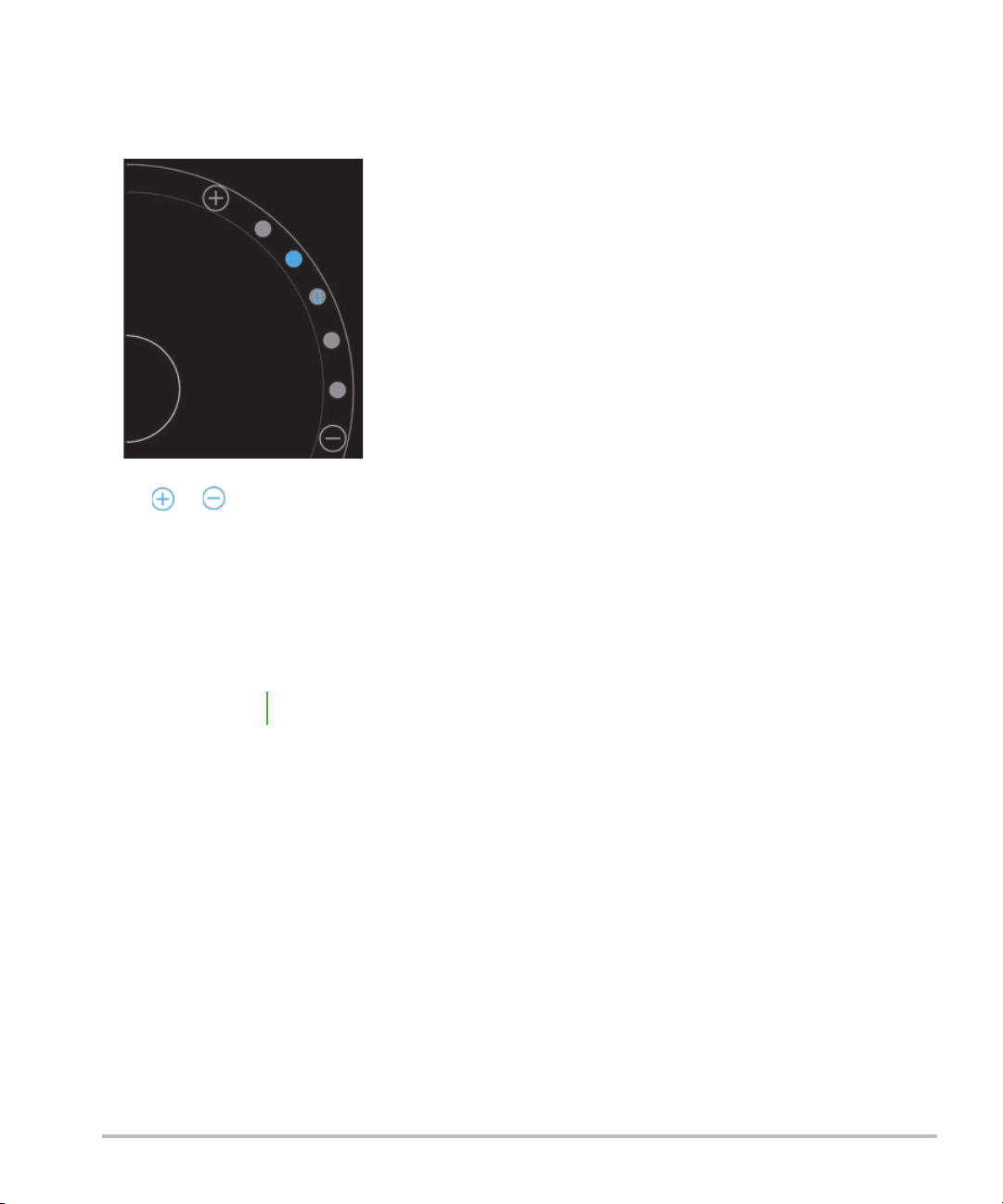
To control the color scale
Scale
1 On the control wheel, tap Scale. The Scale control appears.
2 Tap or to change to a higher or lower blood flow scale (or tap one of the dots for specific blood flow
scale index).
Inverting the blood flow colors
By default, blood flow toward the transducer is shown in red, while blood flow away from the transducer is
displayed in blue. The system lets you reverse this orientation. The current blood flow orientation can be seen
in the upper left of the scanning window.
Note The invert control is disabled in CPD mode.
To inve rt th e b lood flo w colors
On the control wheel, tap Invert.
Filtering
A wall filter removes return signals below certain preset frequencies. This helps eliminate low-frequency, highintensity signals that can interfere with the quality of an image.
Scanning in 2D 49
Page 58

To control wall filtering
Wall
Filter
H
M
L
1 On the control wheel, tap Wall Filter. The Wall Filter control appears.
2 Tap the desired level of filtering:
H - High
M - Medium
L - Low
Controlling flow
To control flow
1 On the control wheel, tap Flow. The Flow control appears.
2 Tap the desired level of flow.
H - High
M - Medium
L - Low
Scanning in M Mode
M Mode shows the motion of structures in the body and can be used to measure the amplitude or frequency
of that movement.
To switch from 2D to M Mode, press and hold 2D.
50 Scanning in M Mode
Page 59

An M (representing M Mode) appears in the scan mode selector.
Moving the M Line
There are two ways to control the M Line. You can use your thumb in the control area or your index finger in
the display area.
To move the M Line using your thumb
Drag the slider up or down.
Up moves the M Line to the left.
Down moves the M Line to the right.
To move the M Line using your finger
In the display area, use your finger to drag the M Line to the location you want.
Updating in M Mode
The Update menu initiates the M Mode sweep, which generates a linear representation of movement
perpendicular to the M Line. This visualization mode is ideal for measuring the amplitude and frequency of
motion.
To initiate an update in M Mode, tap Update.
Changing the sweep speed
You can change the speed of the sweep scan to better isolate individual motions.
Updating in M Mode 51
Page 60

To change the sweep speed
Speed
F
M
S
1 On the control wheel, tap Update.
2 On the control wheel, tap Speed.
3 Tap one of the following:
S - Slow
M - Medium
F - Fast
Setting the image orientation
You can determine the orientation of the image at a glance by seeing which side of the image the SonoSite
logo appears on. The position of the logo corresponds to the physical bump on one side of the transducer
housing.
52 Setting the image orientation
Page 61

To change image orientation
Orient
1 On the control wheel, tap Orient. the orientation control appears.
2 Tap or to move the orientation to up/left or up/right.
Optimizing the image
The following image optimizations are available, depending on the transducer you have selected:
Res - Provides the best possible resolution. This is available with all transducers.
Pen - Provides the best possible penetration. This is available with all transducers.
THI - Tissue Harmonic Imaging (THI) decreases clutter and increases contrast and spatial resolution. This is
currently only available with the P21v transducer.
Optimizing the image 53
Page 62

To optimize the image
Opt
1 On the control wheel, tap Opt. The image optimization control appears.
2 Tap the image optimization option you want.
Note THI optimization is not available for all transducers.
Adjusting depth and gain
Adjusting depth
Depth refers to the depth of display. You can adjust the depth in all imaging modes. Scan depth is always
displayed in the lower left of the scan window.
To adjust scan depth
1 On the control wheel, tap Depth. The depth control appears.
54 Adjusting depth and gain
Page 63

2 Tap or to increase or decrease the scan depth (or tap one of the dots for specific screen-depth
Depth
index).
Adjusting gain
Gain refers to amplifying the intensity of the returning sound waves on the screen display. Increasing the gain
brightens the image. Decreasing the gain darkens the image.
There are two types of gain that can be adjusted.
Overall Gain - Adjusts the amplification of all returning signals.
Near/Far Gain - Adjusts the amplification of signals returning from shallow or deep depths, respectively.
To set Overall Gain
1 On the control wheel, tap Overall Gain. The gain control appears.
Adjusting depth and gain 55
Page 64

2 To set the gain, move the blue dot up and down the slider.
Overall
Gain
Reset
3 If desired, tap Reset to return to the default settings.
To set Near/Far Gain
1 On the control wheel, tap Near/Far Gain. The gain control appears.
2 Tap Near/Far Gain again to toggle between near gain and far gain.
3 To set the gain, move the blue dot up and down the slider.
Controlling the dynamic range
Dynamic range controls the intensity of the gray scale used in the image. A lower setting increases the image
contrast, making echoes appear brighter against a darker background. A higher setting broadens the gray
scale, resulting in a smoother image.
To change the dynamic range
1 On the control wheel, tap Dynamic Range. The dynamic range control appears.
56 Controlling the dynamic range
Page 65

2 Tap or to increase or decrease the dynamic range or tap a dot; the dot in the center is marked with
Dynamic
Range
a 0 to indicate the midpoint.
Accessing guided protocols
SonoSite iViz offers protocols that guide you through all the necessary views for that protocol and supply a
reference image for that view.
Note Guided protocols are only available when using phased array transducers, such as
the P21v.
To access the guided protocols
1 From an unfrozen scan, open the bottom tool drawer by swiping upward on the tool drawer handle in the
lower right of the screen.
2 Tap the class of guided protocol you want to use. A list of available protocols appears in the control area.
Physical
Assistance is available for the following types of exams:
PLAX
PSAX
Apical
Subxiphoid
Accessing guided protocols 57
Page 66

IVC
Aorta
Liver
Right Kidney
Left Kidney
Spleen
Bladder
Lung (Ph.)
eFAST
Extended focused assessment with sonography for trauma (eFAST) is a rapid bedside ultrasound examination.
Assistance is available for the following types of exams:
RUQ
LUQ
Pelvis
Lung (Ph.)
FATE
Focus assessed transthoracic echo (FATE) interprets echocardiographic findings. Assistance is available for the
following types of exams:
PLAX
PSAX
Apical
Subxiphoid
IVC
58 Accessing guided protocols
Page 67

RUSH
Rapid ultrasound for shock and hypotension (RUSH) exam is a quick way to examine the heart, intravascular
compartments, and large arteries. Assistance is available for the following types of exams:
PLAX
PSAX
Apical
Subxiphoid
IVC
Aorta
RUQ
Spleen/LUQ
Pelvis
Lung (Ph.)
Accessing guided protocols 59
Page 68

60 Accessing guided protocols
Page 69

Chapter 6: Managing Images and Clips
SAVE
SonoSite iViz includes tools for capturing, saving, labeling, and reviewing your ultrasound images and clips.
Be aware that images and clips can only be saved to the current study. The current study is the study that is
open during the scan.
Caution
If you did not open an existing study before beginning your scan, a new blank study is created. Be sure to
update the study with the necessary patient and exam information before ending it.
For more information about patient studies and how they are used in the SonoSite iViz system, see Chapter 4,
“Managing Patient Records.”
All images and clips are saved to the study in the order that they were recorded. During a scan, the number of
images and clips saved to the current study is displayed in the SAVE button .
To avoid mixing up images saved from multiple patients, make sure that the correct
patient ID is displayed before you save an image. For more information about
patient records, see Chapter 4, “Managing Patient Records.”
Freezing an image
You must freeze an image before you can perform measurements or add labels.
To freeze an image
1 While scanning, tap FREEZE.
2 If desired:
Freezing an image 61
Page 70

Drag the green slider up and down to scroll through the frames.
Select the back arrow to return to the first frame or the forward arrow to go to the last frame .
Saving an image or a clip
During an exam, you can save an image or clip to the current study.
Caution
To save an image
While scanning on an active or frozen scan, tap SAVE.
The SAVE button turns red momentarily, and the image is saved to the current study.
To save a clip
1 While scanning, press and hold SAVE for one second.
The button shows a blue progress bar, which represents the clip recording length that was set up in
Preferences (see “Configuring preferences” on page 22).
2 To stop recording the clip, tap SAVE.
The clip is saved to the current study (the clip is not saved if it was canceled).
To avoid mixing images saved from multiple patients, make sure that the correct
patient ID is displayed before you save an image. For more information about
finding and retrieving patient records, see Chapter 4, “Managing Patient
Records.”.
62 Saving an image or a clip
Page 71

Reviewing an image or clip
You can view an image or play back any clip saved to a study.
To view an image or clip in the current study
1 Tap the Patient field above the scan image.
2 In the menu area on the left, tap the image you want to view.
To view an image or clip in a different study
1 Open the study that contains the images and clips that you want to view. (For more information about
finding specific studies, see “Searching for a patient record” on page 31.)
2 From the Images and Clips tab, tap the image or clip that you want to view.
Zooming in and out of an image
To zoom in and out of an image, make a pinching or expanding motion with your fingers on the display screen.
For more information about using gestures in the SonoSite iViz system, see “Using gestures” on page 9.
Adding labels
For each exam type, there are a variety of standard labels. In addition, you can create up to 10 custom labels
(with a maximum of 12 characters each).
Reviewing an image or clip 63
Page 72

To add labels and arrows
1 On a frozen or saved image, open the bottom tool drawer by swiping upward on the tool drawer handle in
the lower right of the screen.
2 Tap Text Labels.
3 To add an arrow:
a Ta p +Arrow.
An arrow appears on the display .
b Using your finger, drag the arrow to a location on the screen.
c Using your finger, drag the blue orientation arrows to rotate the center black arrow.
4 To add a standard label:
a Tap the label you want to add, such as Right or Medial.
b Using your finger, drag the label to a location on the screen.
5 To add a custom label (the maximum number of characters you can use for a custom label is 12; don’t use
spaces in the label name):
a Tap the text box at the top of the list of labels.
b Type the text of the label, and then tap Done.
The custom label appears on the screen.
c Using your finger, drag the label to a location on the screen.
6 Tap Save to keep your changes.
64 Adding labels
Page 73

To delete labels and arrows
1 Tap the arrow or label that you want to delete.
2 In the label menu, tap next to the arrow or label you want to delete.
Deleting images and clips
To delete an image or clip
1 From the Patient module, tap the iViz Studies tab.
2 From the list of studies, tap the one from which you would like to delete the image or clip.
3 To delete one image or clip, tap the thumbnail on the left that represents the image or clip you would like
to delete.
4 To delete multiple images or clips:
a Ta p Select.
b Tap the images you want to delete.
Check boxes appears next to those you have selected.
5 Tap , then tap Delete at the prompt.
Sending and sharing images and clips
Caution
To send or share an image or clip
1 From the Patient module, tap the iViz Studies tab.
2 From the list of studies, tap the one from which you would like to share the image or clip.
3 To share one image or clip, tap the thumbnail on the left of the image or clip you would like to share.
4 To share multiple images or clips:
a Ta p Select.
b Tap the images you want to share.
To protect patient data, take appropriate precautions when exporting patient data
to a USB drive.
Deleting images and clips 65
Page 74

Check boxes appear next to those you have selected.
5 Tap .
6 Tap one or more of the following check boxes:
Local PACS - This option sends the image or clip through DICOM. If you select this option, you will be
asked to choose a server from the list.
Tri cefy - This option sends the image or clip through the Tricefy collaborative medical image-sharing
tool. You must set up an account with Tricefy to use this option. SonoSite iViz includes a free 30-day trial
of Tricify. After your 30-day trial is over, you have up to one year to perform an additional 500
collaboration transactions.
USB - This option saves the image or clip to the USB drive inserted in the system.
Email - This option sends the image or clip through the email account set up on the system.
Printer - This option sends the image or clip to the printer set up on the system. For more information
about setting up a printer, see “Adding a wireless printer” on page 21.
7 Click Next.
8 Depending on the option you choose, complete the remaining information on the right side of the screen
(for example, the local PACS server).
9 Click Share.
66 Sending and sharing images and clips
Page 75

Chapter 7: Measurements and Calculations
This chapter provides information about measurements, calculations, worksheets, and reports.
Measurements are performed on frozen images. For references used, see “Measurement References” on
page 81
WAR NIN GS
To avoid misdiagnosis or harming the patient outcome, do not use single
calculations as sole diagnostic criteria. Use calculations in conjunction with other
clinical information.
To help ensure the accuracy of the images obtained, all patient images must be
obtained by qualified and trained individuals.
To avoid a mix-up of patient data, create a new patient study before taking any
measurements.
Taking measurements
Within calculations, you can save measurement results to a patient report. You can display, repeat, and delete
measurements from a calculation. Some measurements can be deleted directly from the patient report pages.
See “Ending a study” on page 35.
Note Except for the Abdomen exam, general measurements appear on-screen only and
are not in a specific report page. Because of this, we recommend that you save the
image with the measurements before ending the study.
Working with calipers
When taking measurements, each caliper appears as a white cross symbol . The active caliper will be
enclosed in a blue circle .
To use the calipers
1 Drag a caliper to the desired position, and release it.
2 Drag the caliper to the end point, and release it.
The on-screen measurement value changes as the caliper moves.
You can move the active caliper by touching anywhere inside the blue circle and dragging it with your finger.
This method can keep you from blocking the clinical view with your finger while measuring. To make a
different caliper active, simply tap it.
Taking measurements 67
Page 76

Viewing and deleting measurement results
The current measurement results appear on the upper left side of the scan area under the Measurements box.
Tap the drop-down arrow to see the measurements you’ve taken.
To delete a measurement
Select the caliper you want to delete, and then tap the red .
Taking basic measurements
Caution:
To measure the distance between two points
1 On a frozen scan, tap Measurements.
2 Under the General measurements area, tap Distance.
3 Drag the active caliper to the first point.
4 Drag the other caliper to the second point.
5 As needed, tap and drag each caliper until it is precisely positioned.
Note The Measurements box can be dragged around the screen to avoid blocking the
To measure the circumference or area using an ellipse
Use the ellipse measurement tool to calculate the size of a circular or oval structure, such as a blood vessel.
1 On a frozen scan, tap Measurements.
Moving the baseline, scrolling, or inverting the trace while frozen causes the cardiac
output results to be cleared from the screen.
clinical view. You can also minimize it by clicking .
68 Taking measurements
Page 77

2 Under the General measurements area, tap Ellipse.
3 Drag the caliper to the boundary of the feature you want to measure. When you lift your finger, a dashed
circle appears, and the ellipse is anchored at that point.
4 Drag the second caliper along the horizontal axis to align it to the rest of the feature you are measuring.
5 Tap the height caliper to make it active.
Taking measurements 69
Page 78

6 Drag the height caliper to the height of the feature you want to measure.
The diameter, area, and circumference measurements appear in the Measurements box.
To measure the circumference or area by tracing
1 On a frozen scan, tap Measurements.
2 Under the General measurements area, tap Tra ce. An active caliper appears on the screen.
3 Drag the caliper to the start point of your measurement, and lift your finger.
70 Taking measurements
Page 79

4 Drag the caliper to outline the structure you want to measure. A dotted line shows the path of the trace.
5 Before you lift your finger, make sure the ends of the trace are close together; that way, the trace
automatically closes, and the area and circumference measurement values appear in the Measurements
box.
About calculations
In SonoSite iViz, you can perform calculations that you then save to a patient report. You can display, repeat,
and delete measurements from a calculation. Some measurements can be deleted directly from a patient
report. See “Ending a study” on page 35.
There are two kinds of calculations:
General calculations that are available for multiple exam types
Specialized calculations that are specific to one exam type
Overview
Once you’ve selected an exam type and have a frozen image, you can access calculations by tapping
Measurements. Then you can select between general and exam-specific measurements from the left side of
the screen.
To expand the list, tap . To collapse the list, tap .
After you select a measurement name, SonoSite iViz highlights it, and calipers appear on the image.
Position the calipers by dragging them. The measurement result appears in the Measurements box beside
the measurement name.
About calculations 71
Page 80

After each measurement is taken, the measurement name in the calculation menu changes color to show that
it is complete.
Calculating volume
You can calculate the volume of a structure by taking up to three separate measurements: length, width, and
height. There are two types of volume calculation methods available: Cuboid and Ellipsoid. The Cuboid
method measures the volume of a rectangular space, while the ellipsoid method measures a rounded, or
spherical shape. The procedure is the same for both calculation methods. To determine which calculation
method your system is using, or to change the setting, see “Configuring preferences” on page 22
To calculate the volume of a structure
1 On a frozen scan, tap Measurements.
2 Under the General measurements area, tap Volume.
An active caliper appears. Steps 3, 4, and 5 can be performed in any order.
3 Measure the length of the structure.
a In the control area, tap Length.
b Drag the active caliper to one side of the structure. When you lift your finger, a new, active caliper
appears.
72 About calculations
Page 81

c Drag the active caliper to the other side of the structure. When you lift your finger, the length value is set.
4 Measure the width of the structure.
a If necessary, unfreeze the image, reposition the transducer to show the width of the feature, freeze the
image, and then tap Measurements.
b In the control area, tap Width.
c Drag the active caliper to one side of the feature. When you lift your finger, a new, active caliper appears.
d Drag the active caliper to the other side of the feature. When you lift your finger, the width value is set.
About calculations 73
Page 82

5 Measure the height of the feature.
a If necessary, unfreeze the image, reposition the transducer to show the height of the structure, freeze the
image, and then tap Measurements.
b In the control area, tap Height.
c Drag the active caliper to the top of the structure. When you lift your finger, a new, active caliper appears.
d Drag the active caliper to the bottom of the structure. When you lift your finger, the height value is set.
The volume of the structure appears in the upper left portion of the screen.
Exam-based calculations
WAR NIN G
To avoid incorrect calculations, verify that the patient information, date, and time
settings are accurate.
Cardiac calculations
WAR NIN G
With the Cardiac exam, you can perform the following calculations:
Table 7-1: Cardiac calculations and results
Calculation list Measurement name (imaging mode) Results
LV Diastole
Moving the baseline, scrolling, or inverting the trace while the image is frozen
causes the displayed cardiac output results to be cleared.
CO
RVWd (2D or M Mode)
RVDd (2D or M Mode)
IVSd (2D or M Mode)
LVDd (2D or M Mode)
LVPWd (2D or M Mode)
Systole
RVWs (2D or M Mode)
CI
EF
SV
SI
LVE SV
LVE DV
IVS
LVP WFT
LVD FS
LV Mass (M Mode)
RVDs (2D or M Mode)
IVSs (2D or M Mode)
LVDs (2D or M Mode)
LVPWs (2D or M Mode)
74 Exam-based calculations
Page 83

Table 7-1: Cardiac calculations and results
Calculation list Measurement name (imaging mode) Results
Area trace MVA (2D)
AVA (2D)
MV Area
AV Area
To measure LVd and LVs
1 From the Exam Type drop-down menu, tap Cardiac.
2 On a frozen 2D image, tap Measurements.
3 Switch to the Cardiac calculation list.
4 Tap LV , and tap the name of the first measurement you want to take.
5 Position the calipers by dragging them.
6 If you want to take additional measurements, tap the measurement name in the calculation list.
To measure Ao, LA, ACS, and LVET
These calculations are available in M-Mode.
1 From the Exam Type drop-down menu, tap Cardiac.
2 On a frozen M-Mode trace, tap Measurements.
3 Switch to the Cardiac calculation list.
4 Under LA/Ao, tap the measurement name.
5 Position the calipers by dragging them.
6 If you want to take additional measurements, tap the measurement name in the calculation list.
To calculate MV or AV area
1 From the Exam Type drop-down menu, tap Cardiac.
2 On a frozen 2D image, tap Measurements.
3 Switch to the Cardiac calculation list.
4 Tap Area, and then tap MVA or AVA.
Exam-based calculations 75
Page 84

5 Position the caliper to where you want to begin the trace, and tap it to start the trace.
6 Using your finger, trace the desired area.
7 Complete the trace, and lift your finger off the caliper.
To measure Heart Rate (HR)
1 From the Exam Type drop-down menu, tap Cardiac.
2 On a frozen M-Mode trace, tap Measurements.
3 Switch to the Cardiac calculation list.
4 Under HR, tap HR in the calculations list.
5 Position the caliper at the peak of a heartbeat, and lift your finger from the screen.
A second caliper appears.
6 Position the second caliper at the peak of the next heartbeat, and lift your finger from the screen.
The heart rate appears.
Obstetrics calculations
WAR NIN G
In SonoSite iViz, you can calculate gestational age and fetal heart rate. You can select authors for Obstetrical
calculations. See “Configuring OB measurements and calculations” on page 24 and “Measurement
publications and terminology” on page 82.
You can select authors for Obstetrical calculations. See “Obstetrical references” on page 86.
EFW is calculated only after the appropriate measurements are completed. If any of these parameters results
in an EDD greater than what the Obstetrical calculation tables provide, the EFW is not displayed.
Note If you change the calculation author during the exam, the common measurements
76 Exam-based calculations
Make sure that you have selected the Obstetrics exam type and the OB author for the
Obstetrical calculation table you intend to use. See “Obstetrical references” on
page 86.
are retained.
Page 85

Table 7-2: Results from system-defined obstetrical measurements and table authors
Calculation result
Gestational Age
a
Gestational
OB measurements
Available authors
YS —
GS Hansmann, Nyberg, Tokyo U.
CRL Hadlock, Hansmann, Osaka, Tokyo
U.
BPD Chitty, Hadlock, Hansmann, Osaka,
Tokyo U.
HC Chitty, Hadlock, Hansmann
AC Hadlock, Hansmann, Tokyo U.
FL Chitty, Hadlock, Hansmann, Osaka,
Tokyo U.
HL Jeanty
Cereb D —
CM —
Lat Vent —
Cx Len —
Estimated Fetal Weight (EFW)
c
HC, AC, FL Hadlock 1
BPD, AC, FL Hadlock 2
AC, FL Hadlock 3
BPD, TTD Hansmann
BPD, FTA, FL Osaka U.
BPD, AC Shepard
BPD, T TD, APTD, FL Tokyo U.
Ratios HC/AC Campbell
FL/AC Hadlock
FL/BPD Hohler
FL/HC Hadlock
Exam-based calculations 77
Page 86

Table 7-2: Results from system-defined obstetrical measurements and table authors
Calculation result
Amniotic Fluid Index
Growth Analysis Tables
a
The Gestational Age is automatically calculated and displayed next to the Obstetrical measurement you selected. The
average of the results is the AUA. Only measurements of the same type are averaged.
b
For Tokyo U., APTD and TTD are used only to calculate EFW. No age or growth tables are associated with these
measurements.
c
The Estimated Fetal Weight (EFW) calculation uses an equation that consists of one or more fetal biometry
measurements. The author for the Obstetrical tables, which you choose on a system setup page, determines the
measurements you must perform to obtain an EFW calculation. Individual selections for Hadlock’s EFW equations
1, 2, and 3 are not determined by the user. The selected equation is determined by the measurements that have
been saved to the patient report with priority given to the order listed above.
d
The Growth Analysis tables are used by the Report Graphs feature. Three growth curves are drawn using the table data
for the selected growth parameter and published author. Growth tables are available only with a user-entered LMP
or EDD.
Gestational
OB measurements
Q1, Q2, Q3, Q
d
BPD Chitty, Hadlock, Jeanty
4
Available authors
Jeng
HC Chitty, Hadlock, Jeanty
AC Chitty, Hadlock, Jeanty
FL Chitty, Hadlock, Jeanty
EFW Brenner, Hadlock, Jeanty
HC/AC Campbell
To measure gestational growth (2D)
For each 2D Obstetrical measurement (except AFI), the system saves up to three individual measurements and
their average. If you take more than three measurements, the earliest measurement is deleted.
1 From the Exam Type drop-down menu, tap OB.
2 On a frozen 2D image, tap Measurements.
3 Switch to the OB calculations list.
4 Do the following for each measurement you want to take:
a Select the calculation list that contains the measurement.
b Tap the measurement name.
c Position the calipers by dragging.
78 Exam-based calculations
Page 87

To measure Heart Rate (HR) in M Mode
1 From the Exam Type drop-down menu, tap OB.
2 On a frozen M-Mode trace, tap Measurements.
3 Switch to the OB calculation list.
4 Under HR, tap HR in the calculations list.
5 Position the caliper at the peak of a heartbeat, and lift your finger from the screen.
A second caliper appears.
6 Position the second caliper at the peak of the next heartbeat, and lift your finger from the screen.
The heart rate appears.
To measure gestational sacs
To make more than one gestational sac measurement on the same frozen image, tap the image to make an
additional measurement, and then tap Save.
To make a single gestational sac measurement, tap Save after the measurement.
Abdomen, breast, lung, MSK, and nerve calculations
To measure distance, see “To measure the distance between two points” on page 68.
To measure volume, see “Calculating volume” on page 72.
Exam-based calculations 79
Page 88

80 Exam-based calculations
Page 89

Chapter 8: Measurement References
This chapter provides information about measurement accuracy, publications, and terminology.
Measurement accuracy
The measurements from the system are of a physical property, such as distance for evaluation by the clinician.
The accuracy values require that you can place the calipers over one pixel. The values do not include acoustic
anomalies of the body.
The 2D linear distance measurement results are displayed in centimeters with one place past the decimal
point if the measurement is 10 or greater and two places past the decimal point if the measurement is less than
10.
The linear distance measurement components have the accuracy and range shown in the following tables.
Table 8-1: 2D Measurement Accuracy and Range
2D Measurement Accuracy
and Range
Axial Distance
Lateral Distance
Diagonal Distance
System
Tolerance
a
< ±2% plus 1% of
full scale
< ±2% plus 1% of
full scale
< ±2% plus 1% of
full scale
Accuracy By Tes t MethodbRange (cm)
Acquisition Phantom 0-26 cm
Acquisition Phantom 0-35 cm
Acquisition Phantom 0-44 cm
< ±4% plus (2% of
Area
c
full scale/smallest
dimension) * 100
Acquisition Phantom 0.01-720 cm2
plus 0.5%
a
Full scale for distance implies the maximum depth of the image.
b
An RMI 413a model phantom with 0.7 dB/cm MHz attenuation was used.
c
The area accuracy is defined using the following equation:
% tolerance = ((1 + lateral error) * (1 + axial error) – 1) * 100 + 0.5%.
d
The circumference accuracy is defined as the greater of the lateral or axial accuracy and by the following equation:
% tolerance = ( 2 (maximum of 2 errors) * 100) + 0.5%.
Measurement accuracy 81
Page 90

Table 8-1: 2D Measurement Accuracy and Range
2D Measurement Accuracy
and Range
System
Tolerance
a
Accuracy By Tes t MethodbRange (cm)
< ±3% plus (1.4%
of full scale/
Circumference
d
smallest
Acquisition Phantom 0.01-96 cm
dimension) * 100
plus 0.5%
a
Full scale for distance implies the maximum depth of the image.
b
An RMI 413a model phantom with 0.7 dB/cm MHz attenuation was used.
c
The area accuracy is defined using the following equation:
% tolerance = ((1 + lateral error) * (1 + axial error) – 1) * 100 + 0.5%.
d
The circumference accuracy is defined as the greater of the lateral or axial accuracy and by the following equation:
% tolerance = ( 2 (maximum of 2 errors) * 100) + 0.5%.
Table 8-2: M Mode Measurement and Calculation Accuracy and Range
M Mode Measurement
Accuracy and Range
Distance
Time
System Tolerance Accuracy By Test Meth o d Range
< +/- 2% plus 1%
of full scale
a
< +/- 2% plus 1%
of full scale
c
Acquisition
Acquisition
Phantom
Phantom
b
d
0-26 cm
0.01-10
sec
< +/- 2% plus (Full
Heart Rate
Scale
e
* Heart
Acquisition
Phantom
f
Rate/100)%
a
Full scale for distance implies the maximum depth of the image.
b
An RMI 413a model phantom with 0.7 dB/cm MHz attenuation was used.
c
The area accuracy is defined using the following equation:
% tolerance = ((1 + lateral error) * (1 + axial error) – 1) * 100 + 0.5%.
d
The circumference accuracy is defined as the greater of the lateral or axial accuracy and by the following equation:
% tolerance = ( 2 (maximum of 2 errors) * 100) + 0.5%.
e
Full scale for time implies the total time displayed on the scrolling graphic image.
f
FUJIFILM SonoSite special test equipment was used.
5-923
bpm
Measurement publications and terminology
The following are the publications and terminology used for each calculation result.
82 Measurement accuracy
Page 91

Terminology and measurements comply with American Institute of Ultrasound in Medicine (AIUM) published
standards.
Cardiac references
Body Surface Area (BSA) in m2
Grossman, W. Cardiac Catheterization and Angiography. Philadelphia: Lea and Febiger, (1980), 90.
BSA = 0.007184 * Weight
0.425
* Height
0.725
Weight = kilograms
Height = centimeters
Cardiac Index (CI) in l/min/m
2
Oh, J.K., J.B. Seward, A.J. Tajik. The Echo Manual. 2nd Edition, Boston: Little, Brown and Company, (1999), 59.
CI = CO/BSA
where: CO = Cardiac Output
BSA = Body Surface Area
Cardiac Output (CO) in l/min
Oh, J.K., J.B. Seward, A.J. Tajik. The Echo Manual. 2nd ed., Lippincott, Williams, and Wilkins, (1999), 59.
CO = (SV * HR)/1000
where: CO = Cardiac Output
SV = Stroke Volume
HR = Heart Rate
Cross Sectional Area (CSA) in cm
2
Reynolds, Terry. The Echocardiographer’s Pocket Reference. 2nd ed., School of Cardiac Ultrasound, Arizona Heart
Institute, (2000), 383.
CSA = 0.785 * D
2
where: D = diameter of the anatomy of interest
Ejection Fraction (EF), percent
Oh, J.K., J.B. Seward, A.J. Tajik. The Echo Manual. 2nd ed., Lippincott, Williams, and Wilkins, (1999), 40.
EF = ((LVEDV – LVESV)/LVEDV) * 100%
where: EF = Ejection Fraction
LVEDV = Left Ventricular End Diastolic Volume
LVESV = Left Ventricular End Systolic Volume
Measurement accuracy 83
Page 92

Heart Rate (HR) in bpm
HR = 3 digit value input by user or measured on M Mode and Doppler image in one heart cycle
Interventricular Septum (IVS) Fractional Thickening, percent
Laurenceau, J. L., M.C. Malergue. The Essentials of Echocardiography. Le Hague: Martinus Nijhoff, (1981), 71.
IVSFT = ((IVSS – IVSD)/IVSD) * 100%
where: IVSS = Interventricular Septal Thickness at Systole
IVSD = Interventricular Septal Thickness at Diastole
Left Atrium/Aorta (LA/Ao)
Feigenbaum, H. Echocardiography. Philadelphia: Lea and Febiger, (1994), 206, Figure 4-49.
Left Ventricular End Volumes (Teichholz) in ml
Teichholz, L.E., T. Kreulen, M.V. Herman, et. al. “Problems in echocardiographic volume determinations:
echocardiographic-angiographic correlations in the presence or absence of asynergy.” American Journal of
Cardiology, (1976), 37:7.
LV E SV = ( 7.0 * LVD S
3
)/(2.4 + LVDS)
where: LVESV = Left Ventricular End Systolic Volume (ml)
LVDS = Left Ventricular Dimension at Systole (cm)
LV E DV = ( 7 .0 * LVD D
3
)/(2.4 + LVDD)
where: LVEDV = Left Ventricular End Diastolic Volume (ml)
LVDD = Left Ventricular Dimension at Diastole (cm)
Left Ventricular Mass in gm
Oh, J.K., J.B. Seward, A.J. Tajik. The Echo Manual. 2nd Edition, Boston: Little, Brown and Company, (1999), 39.
LV Mass = 1.04 [(LVID + PWT + IVST)
3
– LVID3] * 0.8 + 0.6
where: LVID = Internal Dimension
PWT = Posterior Wall Thickness
IVST = Interventricular Septal Thickness
1.04 = Specific gravity of the myocardium
0.8 = Correction factor
Left Ventricular Volume: Biplane Method in ml
Schiller, N.B., P.M. Shah, M. Crawford, et.al. “Recommendations for Quantitation of the Left Ventricle by Two‐
Dimensional Echocardiography.” Journal of American Society of Echocardiography. September‐October 1989,
2:362.
84 Measurement accuracy
Page 93

where: V = Volume in ml
V
4
-- -
a
ibi
L
n
-- -
i 1=
n
=
V
4
---
a
i
2
L
n
---
=
a = Diameter
b = Diameter
n = Number of segments (n=20)
L = Length
i = Segment
Left Ventricular Volume: Single Plane Method in ml
Schiller, N.B., P.M. Shah, M. Crawford, et.al. “Recommendations for Quantitation of the Left Ventricle by Two‐
Dimensional Echocardiography.” Journal of American Society of Echocardiography. September‐October 1989,
2:362.
i=1 to 20
where: V = Volume in ml
a = Diameter of chamber view slice
n = Number of segments (n=20)
L = Length of the chamber view
i = Segment
Left Ventricular Dimension (LVD) Fractional Shortening, percent
Oh, J.K., J.B. Seward, A.J. Tajik. The Echo Manual. Boston: Little, Brown and Company, (1994), 43‐44.
LVDFS = ((LVDD – LVDS)/LVDD) * 100%
where: LVDD = Left Ventricle Dimension at Diastole
LVDS = Left Ventricle Dimension at Systole
Left Ventricular Posterior Wall Fractional Thickening (LVPWFT), percent
Laurenceau, J. L., M.C. Malergue. The Essentials of Echocardiography. Le Hague: Martinus Nijhoff, (1981), 71.
LVPWFT = ((LVPWS – LVPWD)/LVPWD) * 100%
where: LVPWS = Left Ventricular Posterior Wall Thickness at Systole
LVPWD = Left Ventricular Posterior Wall Thickness at Diastole
Stroke Index (SI) in cc/m
2
Mosby’s Medical, Nursing, & Allied Health Dictionary, 4th ed., (1994), 1492.
Measurement accuracy 85
Page 94

SI = SV/BSA
where: SV = Stroke Volume
BSA = Body Surface Area
Stroke Volume (SV) 2D and M Mode in ml
Oh, J.K., J.B. Seward, A.J. Tajik. The Echo Manual. 2nd ed., Boston: Little, Brown and Company, (1994), 44.
SV = (LVEDV – LVESV)
where: SV = Stroke Volume
LVEDV = End Diastolic Volume
LVEDSV = End Systolic Volume
Obstetrical references
Amniotic Fluid Index (AFI)
Jeng, C. J., et al. “Amniotic Fluid Index Measurement with the Four Quadrant Technique During Pregnancy.” The
Journal of Reproductive Medicine, 35:7 (July 1990), 674-677.
Average Ultrasound Age (AUA)
The system provides an AUA derived from the component measurements from the measurement tables.
Estimated Date of Delivery (EDD) by Average Ultrasound Age (AUA)
Results are displayed as month/day/year.
EDD = system date + (280 days – AUA in days)
Estimated Date of Delivery (EDD) by Last Menstrual Period (LMP)
The date entered into the patient information for LMP must precede the current date.
Results are displayed as month/day/year.
EDD = LMP date + 280 days
Estimated Fetal Weight (EFW)
Hadlock, F., et al. “Estimation of Fetal Weight with the Use of Head, Body, and Femur Measurements, A
Prospective Study.” American Journal of Obstetrics and Gynecology, 151:3 (February 1, 1985), 333-337.
Hansmann, M., et al. Ultrasound Diagnosis in Obstetrics and Gynecology. New York: Springer-Verlag, (1986), 154.
Osaka University. Ultrasound in Obstetrics and Gynecology. (July 20, 1990), 103-105.
86 Measurement accuracy
Page 95

Shepard M.J., V. A. Richards, R. L. Berkowitz, et al. “An Evaluation of Two Equations for Predicting Fetal Weight
by Ultrasound.” American Journal of Obstetrics and Gynecology, 142:1 (January 1, 1982), 47-54.
University of Tokyo, Shinozuka, N. FJSUM, et al. “Standard Values of Ultrasonographic Fetal Biometry.” Japanese
Journal of Medical Ultrasonics, 23:12 (1996), 880, Equation 1.
Gestational Age by Last Menstrual Period (LMP)
The gestational age is derived from the LMP date entered on the patient information form.
Results are displayed in weeks and days, and is calculated as follows:
GA(LMP) = System date – LMP date
Gestational Age (GA) by Last Menstrual Period (LMPd)
Same as GA by EDD.
The gestational age derived from the system derived LMP using the Established Due Date entered on the
patient form.
Results are displayed in weeks and days, and is calculated as follows:
GA(LMPd) = System Date – LMPd
Gestational age tables
Abdominal Circumference (AC)
Hadlock, F., et al. “Estimating Fetal Age: Computer-Assisted Analysis of Multiple Fetal Growth Parameters.”
Radiology, 152: (1984), 497-501.
Hansmann, M., et al. Ultrasound Diagnosis in Obstetrics and Gynecology. New York: Springer-Verlag, (1986), 431.
University of Tokyo, Shinozuka, N. FJSUM, et al. “Standard Values of Ultrasonographic Fetal Biometry.” Japanese
Journal of Medical Ultrasonics, 23:12 (1996), 885.
WAR NIN G
The gestational age calculated by your FUJIFILM SonoSite system does not match
the age in the aforementioned reference at the 20.0 cm and 30.0 cm abdominal
circumference (AC) measurements. The implemented algorithm extrapolates the
gestational age from the slope of the curve of all table measurements, rather than
decreasing the gestational age for a larger AC measurement indicated in the
referenced table. This results in the gestational age always increasing with an
increase in AC.
Measurement accuracy 87
Page 96

Biparietal Diameter (BPD)
Chitty, L. S. and D.G. Altman. “New charts for ultrasound dating of pregnancy.” Ultrasound in Obstetrics and
Gynecology 10: (1997), 174-179, Table 3.
Hadlock, F., et al. “Estimating Fetal Age: Computer-Assisted Analysis of Multiple Fetal Growth Parameters.”
Radiology, 152: (1984), 497-501.
Hansmann, M., et al. Ultrasound Diagnosis in Obstetrics and Gynecology. New York: Springer-Verlag, (1986), 440.
Osaka University. Ultrasound in Obstetrics and Gynecology. (July 20, 1990), 98.
University of Tokyo, Shinozuka, N. FJSUM, et al. “Standard Values of Ultrasonographic Fetal Biometry.” Japanese
Journal of Medical Ultrasonics, 23:12 (1996), 885.
Cisterna Magna (CM)
Mahony, B.; P. Callen, R. Filly, and W. Hoddick. “The fetal cisterna magna.” Radiology, 153: (December 1984), 773-
776.
Crown Rump Length (CRL)
Hadlock, F., et al. “Fetal Crown-Rump Length: Re-evaluation of Relation to Menstrual Age (5-18 weeks) with
High-Resolution, Real-Time Ultrasound.” Radiology, 182: (February 1992), 501-505.
Hansmann, M., et al. Ultrasound Diagnosis in Obstetrics and Gynecology. New York: Springer-Verlag, (1986), 439.
Osaka University. Ultrasound in Obstetrics and Gynecology. (July 20, 1990), 20 and 96.
Tokyo University. “Gestational Weeks and Computation Methods.” Ultrasound Imaging Diagnostics, 12:1 (1982-
1), 24-25, Table 3.
Femur Length (FL)
Chitty, L. S. and D.G. Altman. “New charts for ultrasound dating of pregnancy.” Ultrasound in Obstetrics and
Gynecology 10: (1997), 174-179, Table 8, 186.
Hadlock, F., et al. “Estimating Fetal Age: Computer-Assisted Analysis of Multiple Fetal Growth Parameters.”
Radiology, 152: (1984), 497-501.
Hansmann, M., et al. Ultrasound Diagnosis in Obstetrics and Gynecology. New York: Springer-Verlag, (1986), 431.
Osaka University. Ultrasound in Obstetrics and Gynecology. (July 20, 1990), 101-102.
University of Tokyo, Shinozuka, N. FJSUM, et al. “Standard Values of Ultrasonographic Fetal Biometry.” Japanese
Journal of Medical Ultrasonics, 23:12 (1996), 886.
Fetal Trunk Cross-Sectional Area (FTA)
Osaka University. Ultrasound in Obstetrics and Gynecology. (July 20, 1990), 99-100.
88 Measurement accuracy
Page 97

Gestational Sac (GS)
Hansmann, M., et al. Ultrasound Diagnosis in Obstetrics and Gynecology. New York: Springer-Verlag, (1986).
Nyberg, D.A., et al. “Transvaginal Ultrasound.” Mosby Yearbook, (1992), 76.
Gestational sac measurements provide a fetal age based on the mean of one, two, or three distance
measurements; however, Nyberg’s gestational age equation requires all three distance measurements for
an accurate estimate.
Tokyo University. “Gestational Weeks and Computation Methods.” Ultrasound Imaging Diagnostics, 12:1 (1982-
1).
Head Circumference (HC)
Chitty, L. S. and D.G. Altman. “New charts for ultrasound dating of pregnancy.” Ultrasound in Obstetrics and
Gynecology 10: (1997), 174-191, Table 5, 182.
Hadlock, F., et al. “Estimating Fetal Age: Computer-Assisted Analysis of Multiple Fetal Growth Parameters.”
Radiology, 152: (1984), 497-501.
Hansmann, M., et al. Ultrasound Diagnosis in Obstetrics and Gynecology. New York: Springer-Verlag, (1986), 431.
Humerous (HL)
Jeanty, P.; F. Rodesch; D. Delbeke; J. E. Dumont. “Estimate of Gestational Age from Measurements of Fetal Long
Bones.” Journal of Ultrasound in Medicine. 3: (February 1984), 75-79
Occipito-Frontal Diameter (OFD)
Hansmann, M., et al. Ultrasound Diagnosis in Obstetrics and Gynecology. New York: Springer-Verlag, (1986), 431.
Tibia
Jeanty, P.; F. Rodesch; D. Delbeke; J. E. Dumont. “Estimate of Gestational Age from Measurements of Fetal Long
Bones.” Journal of Ultrasound in Medicine. 3: (February 1984), 75-79.
Transverse Trunk Diameter (TTD)
Hansmann, M., et al. Ultrasound Diagnosis in Obstetrics and Gynecology. New York: Springer-Verlag, (1986), 431.
Growth analysis tables
Abdominal Circumference (AC)
Chitty, Lyn S. et al. “Charts of Fetal Size: 3. Abdominal Measurements.” British Journal of Obstetrics and
Gynaecology 101: (February 1994), 131, Appendix: AC-Derived.
Hadlock, F., et al. “Estimating Fetal Age: Computer-Assisted Analysis of Multiple Fetal Growth Parameters.”
Radiology, 152: (1984), 497-501.
Measurement accuracy 89
Page 98

Jeanty P., E. Cousaert, and F. Cantraine. “Normal Growth of the Abdominal Perimeter.” American Journal of
Perinatology, 1: (January 1984), 129-135.
(Also published in Hansmann, Hackeloer, Staudach, Wittman. Ultrasound Diagnosis in Obstetrics and
Gynecology. Springer-Verlag, New York, (1986), 179, Table 7.13.)
Biparietal Diameter (BPD)
Chitty, Lyn S. et al. “Charts of Fetal Size: 2. Head Measurements.” British Journal of Obstetrics and Gynaecology
101: (January 1994), 43, Appendix: BPD-Outer-Inner.
Hadlock, F., et al. “Estimating Fetal Age: Computer-Assisted Analysis of Multiple Fetal Growth Parameters.”
Radiology, 152: (1984), 497-501.
Jeanty P., E. Cousaert, and F. Cantraine. “A Longitudinal Study of Fetal Limb Growth.” American Journal of
Perinatology, 1: (January 1984), 136-144, Table 5.
(Also published in Hansmann, Hackeloer, Staudach, Wittman. Ultrasound Diagnosis in Obstetrics and
Gynecology. Springer-Verlag, New York, (1986), 176, Table 7.8.)
Estimated Fetal Weight (EFW)
Brenner, William E.; D. A. Edelman; C. H. Hendricks. “A standard of fetal growth for the United States of America,”
American Journal of Obstetrics and Gynecology, 126: 5 (November 1, 1976), 555-564; Table II.
Hadlock F., et al. “In Utero Analysis of Fetal Growth: A Sonographic Weight Standard.” Radiology, 181: (1991),
129-133.
Jeanty, Philippe, F. Cantraine, R. Romero, E. Cousaert, and J. Hobbins. “A Longitudinal Study of Fetal Weight
Growth.” Journal of Ultrasound in Medicine, 3: (July 1984), 321-328, Table 1.
(Also published in Hansmann, Hackeloer, Staudach, and Wittman. Ultrasound Diagnosis in Obstetrics and
Gynecology. Springer-Verlag, New York, (1986), 186, Table 7.20.)
Femur Length (FL)
Chitty, Lyn S. et al. “Charts of Fetal Size: 4. Femur Length.” British Journal of Obstetrics and Gynaecology 101:
(February 1994), 135.
Hadlock, F., et al. “Estimating Fetal Age: Computer-Assisted Analysis of Multiple Fetal Growth Parameters.”
Radiology, 152: (1984), 497-501.
Jeanty P, E. Cousaert, and F. Cantraine. “A Longitudinal Study of Fetal Limb Growth.” American Journal of
Perinatology, 1: (January 1984), 136-144, Table 5.
(Also published in Hansmann, Hackeloer, Staudach, Wittman. Ultrasound Diagnosis in Obstetrics and
Gynecology. Springer-Verlag, New York, (1986), 182, Table 7.17.)
90 Measurement accuracy
Page 99

Head Circumference (HC)
Chitty, Lyn S., et al. “Charts of Fetal Size: 2. Head Measurements.” British Journal of Obstetrics and Gynaecology
101: (January 1994), 43, Appendix: HC-Derived.
Hadlock, F., et al. “Estimating Fetal Age: Computer-Assisted Analysis of Multiple Fetal Growth Parameters.”
Radiology, 152: (1984), 497-501.
Jeanty P, E. Cousaert, and F. Cantraine. “A longitudinal study of Fetal Head Biometry.” American J of Perinatology,
1: (January 1984), 118-128, Table 3.
(Also published in Hansmann, Hackeloer, Staudach, Wittman. Ultrasound Diagnosis in Obstetrics and
Gynecology. Springer-Verlag, New York, (1986), 176, Table 7.8.)
Head Circumference (HC)/Abdominal Circumference (AC)
Campbell S., Thoms Alison. “Ultrasound Measurements of the Fetal Head to Abdomen Circumference Ratio in
the Assessment of Growth Retardation,” British Journal of Obstetrics and Gynaecology, 84: (March 1977), 165-
174.
General references
Ellipsoid volume
Beyer, W.H. Standard Mathematical Tables, 28th ed., CRC Press, Boca Raton, FL, (1987), 131.
Volume cm
3
= (4/3) * π * Length/2 * Width/2 * Height/2
Ratio calculations
FL/AC Ratio
Hadlock F.P., R. L. Deter, R. B. Harrist, E. Roecker, and S.K. Park. “A Date Independent Predictor of Intrauterine
Growth Retardation: Femur Length/Abdominal Circumference Ratio,” American Journal of Roentgenology, 141:
(November 1983), 979-984.
FL/BPD Ratio
Hohler, C.W., and T.A. Quetel. “Comparison of Ultrasound Femur Length and Biparietal Diameter in Late
Pregnancy,” American Journal of Obstetrics and Gynecology, 141:7 (Dec. 1 1981), 759-762.
FL/HC Ratio
Hadlock F.P., R. B. Harrist, Y. Shah, and S. K. Park. “The Femur Length/Head Circumference Relation in Obstetric
Sonography.” Journal of Ultrasound in Medicine, 3: (October 1984), 439-442.
Measurement accuracy 91
Page 100

HC/AC Ratio
Campbell S., Thoms Alison. “Ultrasound Measurements of the Fetal Head to Abdomen Circumference Ratio in
the Assessment of Growth Retardation,” British Journal of Obstetrics and Gynaecology, 84: (March 1977), 165-
174.
92 Measurement accuracy
 Loading...