

FujiFilm SonoSite H-Universal Stand, SonoSite Edge Stand User Manual

Edge Stand
H-Universal Stand
User Guide

Manufacturer
FUJIFILM SonoSite, Inc.
21919 30th Drive SE
Bothell, WA 98021 USA
T: 1-888-482-9449 or 1-425-951-1200
F: 1-425-951-1201
EC Authorized Representative
FUJIFILM SonoSite B.V.
Joop Geesinkweg 140
1114 AB Amsterdam,
The Netherlands
Australia Sponsor
FUJIFILM SonoSite Australasia Pty Ltd
114 Old Pittwater Road
BROOKVALE, NSW, 2100
Australia
Caution United States federal law restricts this device to sale by or on the order of a physician.
Edge, M-Turbo, MicroMaxx, Titan, and the SonoSite logo are trademarks or registered trademarks of FUJIFILM
SonoSite, Inc. in various jurisdictions. FUJIFILM is a registered trademark of FUJIFILM Corporation. Value from
Innovation is a trademark of FUJIFILM Holdings America Corporation.
All other trademarks are the property of their respective owners
Patents: US 8,088,071; US 7,591,786; US 7,534,211; US 6,447,451; CA 2372158; and EP 1589878.
Part Number: P12223-05
Publication Date: June 2018
Copyright © 2018 FUJIFILM SonoSite, Inc. All Rights reserved.

Edge Stand
H-Universal Stand
User Guide
Introduction .................................................................................................................................................... 1
Document conventions ................................................................................................................................................................. 2
Getting Help ...................................................................................................................................................................................... 3
Stand features ................................................................................................................................................. 3
Using the stand ............................................................................................................................................... 5
Inserting and removing the ultrasound system .......................................................................................... 5
Connecting the ultrasound system ............................................................................................................... 6
Using peripherals and accessories ................................................................................................................ 7
Printer or bar code scanner .......................................................................................................................................................... 7
Triple Transducer Connect ........................................................................................................................................................... 8
Troubleshooting ............................................................................................................................................. 9
Connectivity diagram ..................................................................................................................................................................... 9
Cables and connectors ................................................................................................................................................................ 10
Cleaning and disinfecting ............................................................................................................................ 12
Safety ............................................................................................................................................................. 13
Electrical safety ............................................................................................................................................................................... 13
Equipment safety ........................................................................................................................................................................... 14
Clinical safety ................................................................................................................................................................................... 15
Electromagnetic compatibility (EMC) ..................................................................................................................................... 15
Labeling symbols ........................................................................................................................................................................... 15
Labeling symbols .......................................................................................................................................... 15
Stand dimensions (approximate) ............................................................................................................................................ 17
Temperature, humidity, and atmospheric pressure limits ............................................................................................. 17
English Deutsch Español Français Italiano Português Nederlands
English Deutsch Español Français Italiano Português
Introduction
This user guide explains how to use the Edge Stand (used with the SonoSite Edge II, SonoSite Edge, and
SonoSite M-Turbo systems) or the H-Universal Stand and peripherals or accessories. For information on a
specific peripheral, see the manufacturer’s instructions included with that product. For information on the
transducers or ultrasound systems, see the ultrasound system user guide.
Introduction 1

If you need to disassemble the stand, refer to its assembly instructions available with the stand at
www.sonosite.com.
WAR NIN GS
To avoid the risk of patient injury, misdiagnosis, or user injury, read all the warnings
in the ultrasound system user guide and supplemental guides.
To avoid injury or equipment damage that could result from the stand toppling
over, do not apply undue force to the stand. Positioning the stand platform at a low
level may help to alleviate this potential hazard.
Document conventions
A WARNING describes precautions necessary to prevent injury or loss of life.
A
Caution describes precautions necessary to protect the products.
A
Note provides supplemental information.
Numbered and lettered steps must be performed in a specific order.
Bulleted lists present information in list format but do not imply a sequence.
Single-step procedures begin with
Symbols and terms used on the system are explained in the ultrasound system user guide.
.
2 Introduction

Getting Help
For technical support, please contact FUJIFILM SonoSite as follows:
English Deutsch Español Français Italiano Português Nederlands
English Deutsch Español Français Italiano Português
Phone
(U.S. or Canada)
Phone
(outside U.S. or Canada)
Fax 425-951-6700
Email ffss-service@fujifilm.com
Web www.sonosite.com
Europe Service Center Main: +31 20 751 2020
Asia Service Center +65 6380-5589
Printed in the U.S.
877-657-8118
425-951-1330, or call your local representative
English support: +44 14 6234 1151
French support: +33 1 8288 0702
German support: +49 69 8088 4030
Italian support: +39 02 9475 3655
Spanish support: +34 91 123 8451
Stand features
The stand provides a mobile work platform and a storage area for transducers and other supplies. It also
provides connections for accessories and peripherals.
WAR NIN GS
Stand features 3
To avoid injury or equipment damage that could result from the stand toppling
over, always install the color printer on the front side of the stand, as shown in
Figure 1.
When installed on the stand, the base of the color printer should not be higher
than 50 cm from the floor.
1
1
2
2
4
3
4
3
5
5
6
7
9
9
8 8
10
10
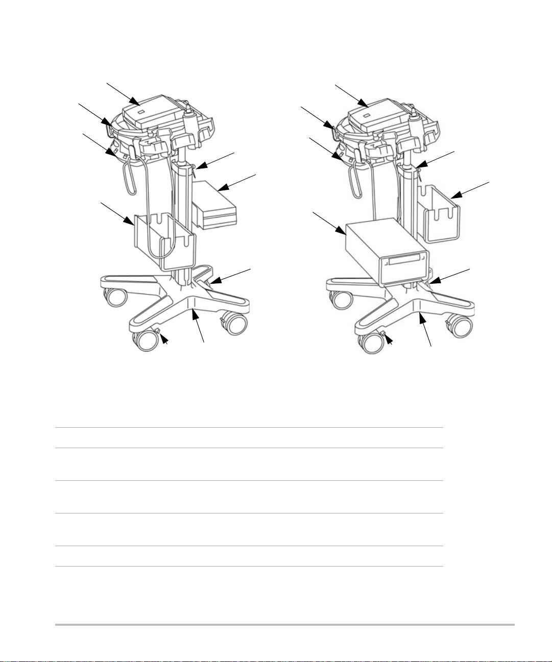
Figure 1 Stand with accessories. The drawing on the left shows the H-Universal Stand with the
M-Turbo ultrasound system and optional basket and black-and-white printer. The drawing on the right shows
the H-Universal Stand with the M-Turbo ultrasound system and optional basket and color printer.
1 Ultrasound system 6 Black-and-white printer
2 Hook (1 of 4) for cables and other
7 Color printer
items
3 Triple Transducer Connect 8 AC adapter 1: Connector for system
power cord
4 Height-adjustment lever 9 AC adapter 2: Connector for AC
power cord (inside stand base)
5 Basket or storage bin* 10 Locking lever on wheel
*Storage bin is positioned on the opposite side of the printer. Refer to the Storage Bin Installation
Instructions.
4 Stand features

Using the stand
To raise or lower the system platform
1 Make sure that the area above the platform is clear.
2 Facing the back of the stand, turn the height-adjustment lever counter-clockwise.
The pole may rise automatically from the column.
3 Raise or lower the pole to the desired height, and then tighten the lever.
To tighten the lever, turn it clockwise.
If lowering the pole, avoid grasping its base. Skin could get caught and pinched in the gap.
4 If you want to reposition the lever (for example, parallel to the pole), pull the lever out, turn it to the desired
position, and release.
To lock or unlock a wheel
Push the locking lever on the wheel:
Push down to lock.
Push up to unlock.
English Deutsch Español Français Italiano Português Nederlands
English Deutsch Español Français Italiano Português
Inserting and removing the ultrasound system
To insert the ultrasound system
1 Rotate system latches outward.
2 Place the ultrasound system on the system platform, ensuring that the transducer cable is positioned
between the handles of the stand.
3 Secure by rotating the system latches inward.
To remove the ultrasound system
1 Disconnect any cords, cables, or TTC attached to the system.
2 Rotate latches outward.
3 Lift the ultrasound system.
Using the stand 5
Connecting the ultrasound system
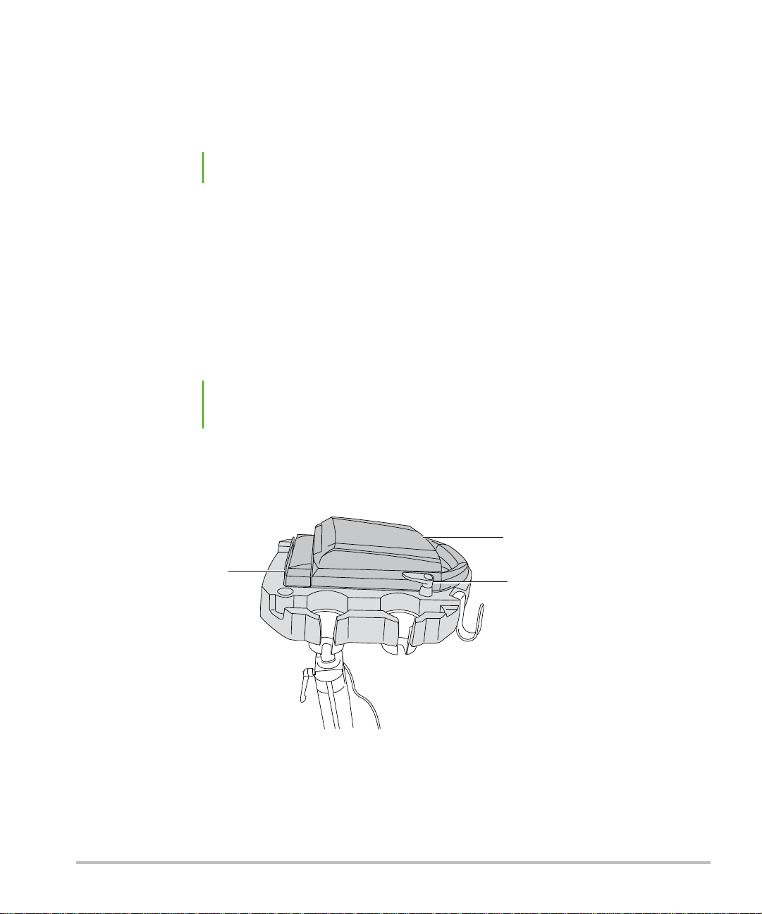
Mini-dock
System
System latch
Attach the mini-dock if you use the system with AC-powered peripherals.
To att ach the mini-dock
Note Make sure that the battery is installed before you attach the mini-dock.
1 Turn off the ultrasound system.
The mini-dock may not function properly if you connect the system while the power is on.
2 Place the mini-dock on the system platform.
3 Slide the mini-dock feet under the ultrasound system and firmly press the mini-dock into the I/O connector
on the back of the system.
The mini-dock is correctly attached when no gap is between the system and mini-dock.
See Figure 2.
Note If at any time the ultrasound system should lose connectivity, turn off the system
and reattach the mini-dock and system.
Always verify that the mini-dock and system are correctly attached after changing a transducer. When you
change a transducer, the mini-dock may loosen.
Figure 2 System platform with system and mini-dock attached (H-Universal stand with M-Turbo system
shown).
6 Connecting the ultrasound system

To connec t AC p ower
1 If using a mini-dock, ensure that it is connected to the system.
2 Connect the cables. See “Cables and connectors” on page 10.
DC power cord (A)
System AC power cord (K)
Using peripherals and accessories
Caution To avoid damaging the system, use only accessories and peripherals recommended
by SonoSite with the ultrasound system.
For specific information on using a peripheral, including warnings and cautions, see the manufacturer’s
operating instructions. For the bar code scanner, see also Bar Code Scanner User Guide.
To connect a peripheral or accessory, see its assembly instructions.
Optional Peripherals and Accessories for Stand
AC-powered peripherals USB peripherals Accessories
Black-and-white printer
Color printer
(MicroMaxx, or TITAN) Serial bar
code scanner
(SonoSite Edge II, Edge,
M-Turbo) USB bar code scanner
(SonoSite Edge II, Edge,
M-Turbo) USB footswitch
Mini-dock
Tri ple Tra nsducer Co nnect
English Deutsch Español Français Italiano Português Nederlands
English Deutsch Español Français Italiano Português
Printer or bar code scanner
You configure the system for the printer or serial bar code scanner on the system’s Connectivity setup page.
For instructions, see the ultrasound system user guide.
For additional information on the bar code scanner, see the Bar Code Scanner User Guide.
To print the screen
1 Turn on the printer.
2 (Color Printer Only) Change the input setting from S-video to video.
3 Do one of the following:
Use the controls on the printer for printing images. Follow the manufacturer’s instructions.
Using peripherals and accessories 7
If the large A or B key (SonoSite Edge II, Edge, M-Turbo) or Delta key (MicroMaxx or TITAN) is programmed
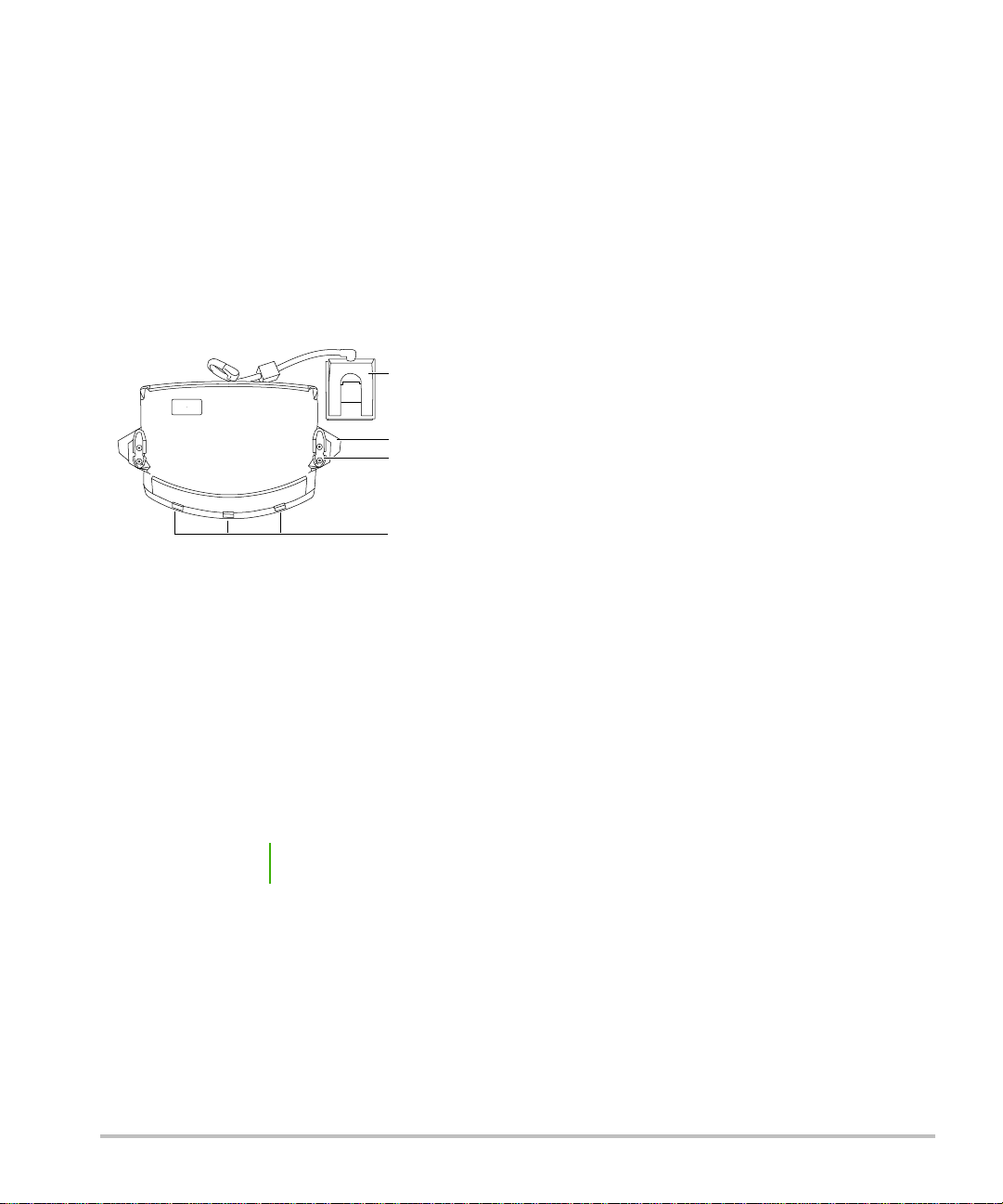
Mounting post
Handle
Tra nsduc er
select buttons
Tra nsduc er
connector
to print, press it. For instructions to program the key, see the ultrasound system user guide.
You can also save images and print them from the patient list. For instructions, see the ultrasound system user
guide.
Triple Transducer Connect
The Triple Transducer Connect (TTC) is an optional three-transducer module that lets you simultaneously
connect up to three transducers while the ultrasound system is docked.
Figure 3 Triple Transdu cer Connec t
To connect a transducer to the TTC
1 Pull the transducer latch up and rotate 90°.
2 Align and insert the transducer connector to the connector on the bottom of the TTC.
3 Turn the latch and press down, securing the transducer connector to the TTC.
To select a transducer
Note When you use the TTC, there may be a minor reduction of transducer penetration.
Push a transducer select button on the TTC.
When selecting another transducer, the system restarts. The light on the button flashes momentarily and then
turns solid green.
Only one transducer is accessible at a time.
8 Using peripherals and accessories

To remove the TTC
1 Remove any attached transducers.
2 Disconnect the transducer connector from the system.
3 Pull out the knob on each of the two mounting brackets, and slide the TTC out.
Troubleshooting
Symptom Solution
Printer does not print. Check the printer selection on the Connectivity setup page.
See the ultrasound system user guide.
Check the cable connections. See the printer installation instructions.
Ensure that the printer is turned on and set up properly. See the printer
manufacturer’s instructions, if necessary.
English Deutsch Español Français Italiano Português Nederlands
English Deutsch Español Français Italiano Português
Stand tips over more easily
than expected.
Lower the platform on the stand.
Avoid placing heavy objects on the platform. Too much weight on the
platform can cause the stand to become less stable.
Connectivity diagram
Use the following diagram for assistance disconnecting and reconnecting peripherals. For more detailed
information, refer to the assembly instructions. Additional copies are available at www.sonosite.com.
See also “Cables and connectors” on page 10.
Caution To avoid damaging the system, use only accessories and peripherals recommended
by SonoSite with the ultrasound system.
Troubleshooting 9

Connectivity of printer and system
A
H
C
Remote
Composite video in
AC in
J
Printer
System/dockSystem/dock
To AC Power
(wall outlet)
K
AC
adapter 1
AC
adapter 2
Stand Base Stand Base
System
Power
Supply
System
Power
Supply
System/dock
Printer
Remoter
Composite video in
AC in
System
Power
Supply
Stand Base
AC
adapter 1
AC
adapter 2
To AC Po wer
(wall outlet)
Cables and connectors
Table 1: Connectivity symbols on mini-docks
Symbol Definition Symbol Definition
DC input S-video in
Print control DVI video out
USB Composite video out
Ethernet Audio out
RS-232 (DVD recorder, VCR, or bar code scanner) ECG/Footswitch
S-video out
10 Troubleshooting
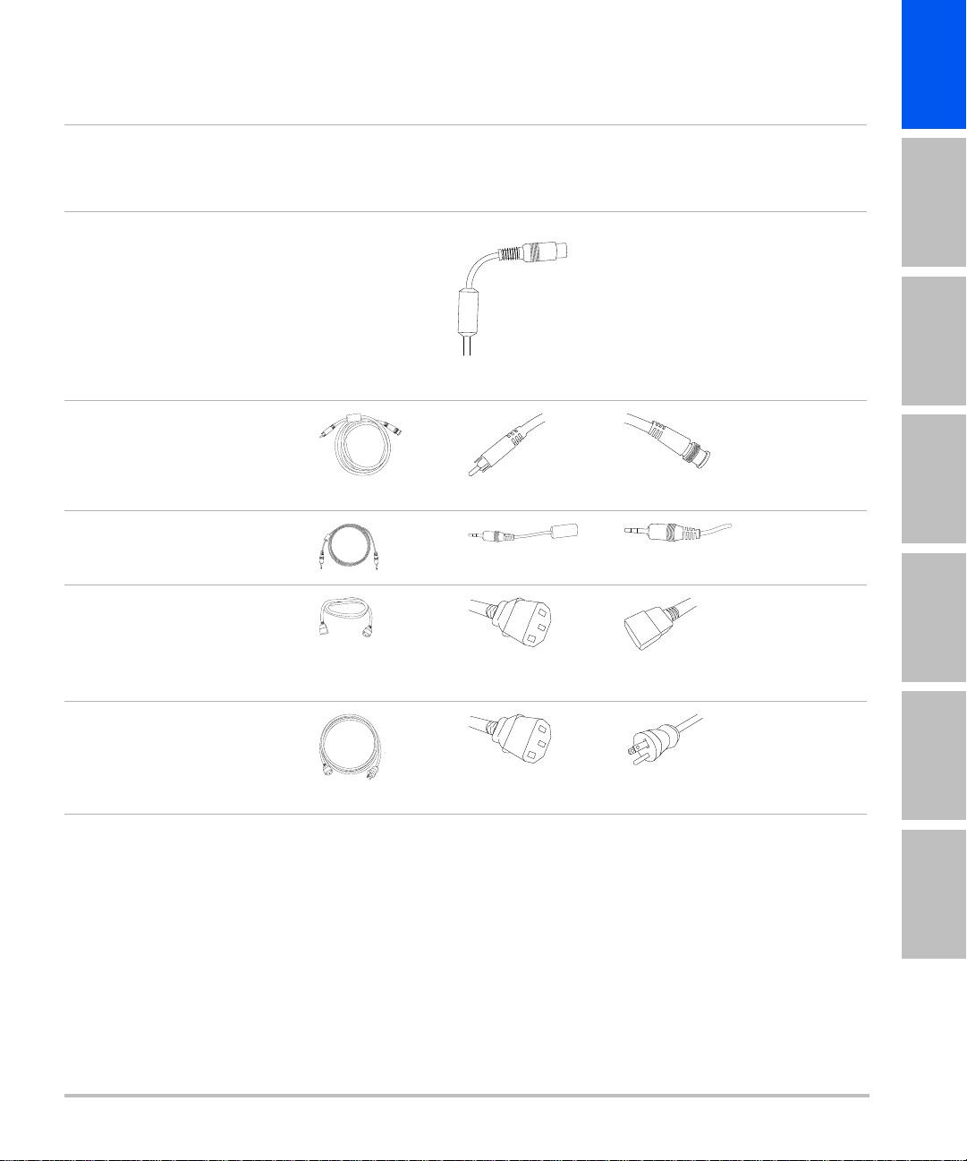
Table 2: Cables and connectors
English Deutsch Español Français Italiano Português Nederlands
English Deutsch Español Français Italiano Português
Letter
Name
Length
A DC power supply
cord
6.8 ft./2 m
C Composite
video cable
6ft./1.8m
H Print control cable
6ft./1.8m
J AC power cord
39 in./1 m
Illustration
See “Stand
features” on
page3.
Connector 1
[Illustration]
[Connects to]
System or minidock
Connector 2
[Illustration]
[Connects to]
Pre-installed
Peripheral
n/a
Printer
Mini-dock
Printer
Printer
Mini-dock
Printer
Printer
Printer
AC adapter 2 on
stand base
K System AC
n/a
power cord
10 ft./3 m
AC adapter 1 on
stand base
Troubleshooting 11
Wall outlet

Cleaning and disinfecting
WAR NIN GS
Caution Use only recommended cleaners or disinfectants on surfaces. Immersion-type
To clean and disinfect a peripheral, refer to its manufacturer’s instructions. For the bar code scanner, see also
the Bar Code Scanner User Guide.
To avoid electrical shock, before cleaning always disconnect the system from the
power supply and remove it from the stand.
To avoid injury, always use protective eyewear and gloves when performing
cleaning and disinfecting procedures.
To avoid infection:
Ensure that the solution expiration date has not passed.
The level of disinfection required for a product is dictated by the type of tissue it
contacts during use. Ensure that the solution strength and duration of contact
are appropriate for the equipment. For information, see the disinfectant label
instructions and the recommendations of the Association for Professionals in
Infection Control and Epidemiology (APIC) and FDA.
disinfectants are not tested for use on surfaces.
To clean and disinfect the stand or TTC
You can clean and disinfect the exterior surface of the stand or TTC using a recommended cleaner or
disinfectant. For the most recent list of approved products, see www.sonosite.com.
1 Turn off the ultrasound system and any accessory equipment. Disconnect the system and accessory
equipment from AC power.
2 Clean the surfaces of the stand to remove any debris or bodily fluids. Use the following procedure:
12 Cleaning and disinfecting

a Use either a pre-moistened wipe or a soft cloth dampened with cleaner or disinfectant.
Approved cleaners and disinfectants for the stand
English Deutsch Español Français Italiano Português Nederlands
English Deutsch Español Français Italiano Português
Cleaner/disinfectant
SaniCloth AF3 (gray top)
Minimum wet contact time
2
3 minutes
1
SaniCloth Plus (red top) 3 minutes
PI-Spray II 10 minutes
1
For maximum effectiveness, the component being cleaned must remain wet with disinfectant for a
minimum period of time.
2
Qualified for use as an intermediate-level disinfectant for mycobacteria. For a more complete list, refer to
the cleaning and disinfection tool available at www.sonosite.com/support/cleaners-disinfectants.
b Remove all gel, debris, and bodily fluids from the stand.
c With a new wipe, clean all parts of the stand by wiping from the clean areas to the soiled areas. This
method helps to avoid cross-contamination.
d Observe the minimum wet contact time. Monitor the stand parts for wet appearance. Re-apply with a
new wipe if no longer wet.
3 Allow the stand to air dry in a clean, well-ventilated space.
For information about cleaning the peripherals, see the manufacturer’s instructions.
Safety
Observe the following warnings and cautions before using accessories and peripherals with the ultrasound
system and transducers.
Electrical safety
The stand is not an electrical device and does not require ground bond testing. The stand is for facilitating the
mobility of peripherals and their connection to the ultrasound system.
Safety 13

WAR NIN GS
Equipment safety
To avoid the risk of electrical shock:
Do not plug the power cord of the Edge Stand or H-Universal Stand into a
multiple portable socket outlet (MPSO) or use an extension cord.
Use only properly grounded equipment. Shock hazards exist if the power supply
is not properly grounded. Grounding reliability can only be achieved when
equipment is connected to a receptacle marked “Hospital Only” or “Hospital
Grade” or the equivalent. The grounding wire must not be removed or defeated.
Use only accessories and peripherals recommended by SonoSite, including the
power supply. Connection of accessories and peripherals not recommended by
SonoSite could result in electrical shock. Contact SonoSite or your local
representative for a list of accessories and peripherals available from or
recommended by SonoSite.
To avoid the risk of electrical shock or injury, the equipment shall be connected
to a center-tapped single phase supply circuit when users in the United States
connect the equipment to a 240V supply system.
To avoid the risk of electrical shock and fire hazard, inspect the power supply, plugs,
cables, and power cords on a regular basis for damage.
Cautions Excessive bending or twisting of cables can cause a failure or intermittent
operation.
Improper cleaning or disinfecting of any part of the accessories and peripherals
can cause permanent damage. For cleaning and disinfecting instructions, see
“Cleaning and disinfecting” on page 12 and the manufacturer’s operating
instructions.
Accessible metal on the signal inputs and outputs on the back and side of the
ultrasound system is not protectively earthed. Do not perform a high current
ground impedance test involving this part.
14 Safety

Clinical safety
REF
To avoid misdiagnosis, do not use non-medical (commercial) grade peripheral
WAR NIN G
monitors. These monitors have not been verified or validated by SonoSite as
being suitable for diagnosis.
Electromagnetic compatibility (EMC)
See the safety section of the ultrasound system user guide and supplemental guides for information on
electromagnetic compatibility with IEC 60601-1-2, including the Manufacturer’s Declaration.
Labeling symbols
The following symbols are used on the products, packaging, and containers.
Symbol Definition
Follow instructions for use
English Deutsch Español Français Italiano Português Nederlands
English Deutsch Español Français Italiano Português
Reading the accompanying documentation is necessary for safe operation of the
medical device
Manufacturer, or Manufacturer and date of manufacture
Authorized representative in the European Community
Class 1 device indicating manufacturer’s declaration of conformance with Annex VII of
93/42/EEC
Catalog number
Collect separately from other household waste (refer to European Commission
Directive 93/86/EEC). Refer to local regulations for disposal.
Safety 15
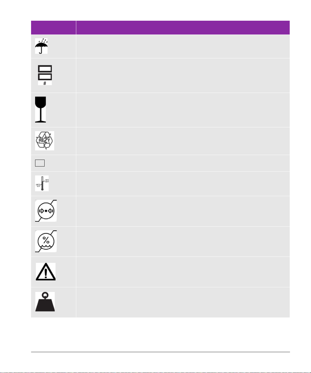
Symbol Definition
SN
46 kg
Do not get wet
Do not stack over # high, where # represents the number on the label
Fragile
Paper recycle
Serial number type of control number
Temperature limitation
Atmospheric pressure limitation
Humidity limitations
Caution
Total equipment mass
16 Safety

Specifications
For information on the peripherals, see the manufacturer’s specifications.
Stand dimensions (approximate)
Width: 20.25 in. (51.4 cm)
Depth: 22 in. (55.9 cm)
Height: 45 in. (114.3 cm) maximum, 33 in. (83.8 cm) minimum
Height range: 12 in. (30.5 cm)
Weight: 40.0 lbs. (18.1 kg)
Safe working load per storage bin: 5 kg
Total stand weight with system and peripherals: 46 kg maximum
Temperature, humidity, and atmospheric pressure limits
English Deutsch Español Français Italiano Português Nederlands
English Deutsch Español Français Italiano Português
Operating: 10–40°C; 15–95% R.H., 700 to 1060 hPa
Shipping/Storage: -35–65°C; 15–95% R.H., 500 hPa to 1060 hPa
Specifications 17

18 Specifications

Edge-Stativ
H-Universal-Stativ
Benutzerhandbuch
Einführung .................................................................................................................................................... 19
Dokumentkonventionen ............................................................................................................................................................ 20
Weiterführende Informationen ................................................................................................................................................ 21
Optionen des Stativs .................................................................................................................................... 21
Verwenden des Stativs ................................................................................................................................. 23
Einsetzen und Entfernen des Ultraschallsystems ...................................................................................... 23
Anschließen des Ultraschallsystems ........................................................................................................... 24
Verwenden von Peripheriegeräten und Zubehör ..................................................................................... 25
Drucker oder Barcode-Leser ...................................................................................................................................................... 25
Triple Transducer Connect ......................................................................................................................................................... 26
Fehlersuche ................................................................................................................................................... 27
Anschlussübersicht ....................................................................................................................................................................... 27
Kabel und Anschlüsse .................................................................................................................................................................. 28
Reinigung und Desinfektion ........................................................................................................................ 30
Sicherheit ...................................................................................................................................................... 31
Elektrische Sicherheit ................................................................................................................................................................... 31
Gerätesicherheit ............................................................................................................................................................................. 32
Klinische Sicherheit ....................................................................................................................................................................... 33
Elektromagnetische Verträglichkeit (EMV) ........................................................................................................................... 33
Kennzeichnungssymbole ........................................................................................................................................................... 33
Kennzeichnungssymbole ............................................................................................................................. 33
Stativabmessungen (ungefähr) ................................................................................................................................................ 35
Temperatur, Feuchtigkeit und Luftdruckgrenzwerte ....................................................................................................... 35
English Deutsch Español Français Italiano Português
Einführung
Dieses Benutzerhandbuch beschreibt die Verwendung des Edge-Stativs (mit den Systemen SonoSite Edge II,
SonoSite Edge und SonoSite M-Turbo) oder des H-Universal-Stativs und der Peripheriegeräte und
Zubehörteile. Weitere Informationen zu einem bestimmten Peripheriegerät entnehmen Sie der mit dem
jeweiligen Produkt gelieferten Bedienungsanleitung des Herstellers. Informationen zu den Schallköpfen und
Ultraschallsystemen finden Sie im Benutzerhandbuch für das Ultraschallsystem.
Einführung 19
Nederlands

Falls Sie das Stativ demontieren müssen, entnehmen Sie entsprechende Informationen bitte den
Montageanweisungen, die dem Stativ beigefügt sind oder unter www.sonosite.com zur Verfügung stehen.
WAR NHI NWEI SE
Um eine Verletzung des Patienten, eine Fehldiagnose oder eine
Verletzung des Bedieners zu vermeiden, müssen die Warnhinweise im
Benutzerhandbuch des Ultraschallsystems und in den ergänzenden
Handbüchern sorgfältig gelesen werden.
Um Verletzungen oder Geräteschäden zu vermeiden, die durch ein
Umkippen des Stativs entstehen könnten, darf keine übermäßige Kraft
auf das Stativ angewandt werden. Das Einstellen der Stativplattform auf
eine tiefe Position kann dazu beitragen, diese potenzielle Gefahr zu
verringern.
Dokumentkonventionen
Ein WARNHINWEIS beschreibt die notwendigen Vorsichtsmaßnahmen zur Vermeidung einer Verletzung
oder eines tödlichen Unfalls.
Ein
Vorsichtshinweis beschreibt die notwendigen Vorsichtsmaßnahmen zum Schutz der Produkte.
Ein
Hinweis enthält ergänzende Informationen.
Nummerierte oder mit Buchstaben versehene Schritte müssen in einer bestimmten Reihenfolge
durchgeführt werden.
Listen mit Gliederungspunkten stellen Informationen in einem Listenformat dar, schreiben jedoch keine
Reihenfolge vor.
Einzelschrittverfahren beginnen mit
.
Die im Zusammenhang mit dem System verwendeten Symbole und Begriffe werden im Benutzerhandbuch
des Ultraschallsystems erklärt.
20 Einführung

Weiterführende Informationen
Der technische Kundendienst von FUJIFILM SonoSite ist wie folgt erreichbar:
English Deutsch Español Français Italiano Português
Te le fo n
(USA und Kanada)
Te le fo n
(außerhalb USA und
Kanada)
Fax +1-425-951-6700
E-Mail ffss-service@fujifilm.com
Web www.sonosite.com
Europäisches
Servicezentrum
Asiatisches
Servicezentrum
Gedruckt in den USA.
+1-877-657-8118
+1-425-951-1330 oder wenden Sie sich an Ihren örtlichen
Kundendienstvertreter
Hauptstelle: +31 20 751 2020
Kundendienst auf Englisch: +44 14 6234 1151
Kundendienst auf Französisch: +33 1 8288 0702
Kundendienst auf Deutsch: +49 69 8088 4030
Kundendienst auf Italienisch: +39 02 9475 3655
Kundendienst auf Spanisch: +34 91 123 8451
+65 6380-5589
Optionen des Stativs
Das Stativ bietet eine mobile Arbeitsplattform und ermöglicht die Unterbringung der Schallköpfe und anderer
Zubehörkomponenten. Außerdem bietet es Anschlussmöglichkeiten für Zubehör und Peripheriegeräte.
WAR NHI NWEI SE
Optionen des Stativs 21
Um Verletzungen oder Beschädigungen des Geräts durch Umfallen des
Stativs zu vermeiden, montieren Sie die Farbdrucker immer auf der
Vorderseite des Stativs, wie in Abbildung1 gezeigt.
Im installierten Zustand sollte der Abstand zwischen der Unterseite des
Farbdruckers und dem Boden nicht mehr als 50 cm betragen.
Nederlands

Abbildung 1 Stativ mit Zubehör. Die linke Abbildung zeigt das H-Universal-Stativ mit dem M-Turbo
1
1
2
2
4
3
4
3
5
5
6
7
9
9
8 8
10
10
Ultraschallsystem, einem optionalen Korb und dem Schwarzweißdrucker. Die rechte Abbildung zeigt das
H-Universal-Stativ mit dem M-Turbo Ultraschallsystem, einem optionalen Korb und dem Farbdrucker.
1 Ultraschallsystem 6 Schwarzweißdrucker
2 Haken (1 von 4) für Kabel und
7Farbdrucker
Sonstiges
3 Triple Transducer Connect 8 Netzadapter 1: Anschluss für das
4 Hebel zur Höhenverstellung 9 Netzadapter 2: Anschluss für das
Stromversorgungskabel des Systems
Netzstromkabel (innerhalb der Stativbasis)
5 Korb oder Aufbewahrungsbehälter 10 Sperrhebel für Rad
*Der Aufbewahrungsbehälter befindet sich auf der gegenüberliegenden Seite des Druckers.
Beachten Sie die Montageanleitung für den Aufbewahrungsbehälter.
22 Optionen des Stativs

Verwenden des Stativs
So heben oder senken Sie die Systemplattform
1 Stellen Sie sicher, dass sich über der Plattform keine Hindernisse befinden.
2 Drücken Sie den Hebel zur Höhenverstellung gegen den Uhrzeigersinn, von der Stativrückseite aus
gesehen.
Der Schaft wird u. U. automatisch aus der Tragsäule nach oben bewegt.
3 Schaft bis zur gewünschten Höhe anheben bzw. absenken und Hebel festziehen.
Um den Hebel festzuziehen, muss er im Uhrzeigersinn gedreht werden.
Halten Sie den Schaft beim Absenken nicht an der Basis fest. Sie könnten sich sonst die Finger klemmen.
4 Wenn Sie den Hebel verstellen möchten (zum Beispiel parallel zum Schaft), ziehen Sie ihn heraus, bringen
Sie ihn in die gewünschte Position und lassen Sie wieder los.
So sperren und entsperren Sie die Räder
Drücken Sie den Sperrhebel auf dem Rad:
Herunterdrücken zum Sperren.
English Deutsch Español Français Italiano Português
Nach oben drücken zum Entsperren.
Einsetzen und Entfernen des Ultraschallsystems
So setzen Sie das Ultraschallsystem ein
1 Systemverriegelungen nach außen drehen.
2 Das Ultraschallsystem auf die Systemplattform stellen; dabei muss sichergestellt werden, dass das
Schallkopfkabel zwischen den Griffen des Stativs positioniert ist.
3 System durch Drehen der Systemverriegelungen nach innen sichern.
So entfernen Sie das Ultraschallsystem
1 Alle an das System angeschlossenen Leitungen, Kabel oder TTCs entfernen.
2 Verriegelungen nach außen drehen.
3 Das Ultraschallsystem anheben.
Nederlands
Verwenden des Stativs 23

Anschließen des Ultraschallsystems
Mini-Dock
System
Systemverriegelung
Das Mini-Dock anschließen, falls das System mit wechselstrombetriebenen Peripheriegeräten verwendet
wird.
So schließen Sie das Mini-Dock an
Hinweis Vergewissern Sie sich vor dem Anschließen des Mini-Docks, dass die Batterie
eingesetzt ist.
1 Ultraschallsystem ausschalten.
Das Mini-Dock funktioniert eventuell nicht einwandfrei, wenn es bei eingeschaltetem System
angeschlossen wird.
2 Mini-Dock auf die Systemplattform stellen.
3 Mini-Dock-Füße unter das Ultraschallsystem schieben und das Mini-Dock fest in den E/A-Anschluss an der
Geräterückseite drücken.
Das Mini-Dock ist ordnungsgemäß angeschlossen, wenn das System lückenlos mit dem Mini-Dock
abschließt. Siehe Abbildung 2.
Hinweis Wenn das Ultraschallsystem zu irgendeinem Zeitpunkt die Verbindung verliert, das
System ausschalten und Mini-Dock und System neu anschließen.
Nach dem Wechseln des Schallkopfes stets sicherstellen, dass das Mini-Dock ordnungsgemäß an das System
angeschlossen ist. Beim Auswechseln von Schallköpfen kann sich das Mini-Dock lockern.
Abbildung 2 Systemplattform mit angeschlossenem Gerät und Mini-Dock (H-Universal-Stativ mit M-Turbo-
System abgebildet)
24 Anschließen des Ultraschallsystems

So schließen Sie das System an die Stromversorgung an
1 Bei Verwendung eines Mini-Docks ist sicherzustellen, dass es an das System angeschlossen ist.
2 Schließen Sie die Kabel an. Siehe „Kabel und Anschlüsse“ auf Seite 28.
Netzkabel (Gleichstrom) (A)
Netzstromkabel für das System (K)
Verwenden von Peripheriegeräten und Zubehör
Vorsichtshinweis Um eine Beschädigung des Systems zu vermeiden, dürfen nur von
SonoSite empfohlene Zubehörteile und Peripheriegeräte mit dem System
benutzt werden.
Spezifische Informationen zur Verwendung eines Peripheriegeräts, einschließlich Warn- und
Vorsichtshinweise, finden Sie in den Bedienungsanweisungen des jeweiligen Herstellers. Informationen über
den Barcode-Leser finden Sie im Benutzerhandbuch für den Barcode-Leser.
Beim Anschluss von Peripheriegeräten oder Zubehör konsultieren Sie bitte die jeweilige Montageanweisung.
Optionale Peripheriegeräte und Zubehör für das Stativ
English Deutsch Español Français Italiano Português
Strombetriebene
Peripheriegeräte
Schwarzweißdrucker
Far bdru cker
(MicroMaxx oder TITAN)
Serieller Barcode-Leser
USB-Peripheriegeräte Zubehör
(SonoSite Edge II, Edge,
M-Turbo) USB-Barcode-Leser
(SonoSite Edge II, Edge,
M-Turbo) USB-Fußschalter
Mini-Dock
Tri ple Tra nsducer Co nnect
Drucker oder Barcode-Leser
Sie können das System für den Drucker oder seriellen Barcode-Leser auf der systemseitigen Seite
„Connectivity“ (PC-Anbindung) konfigurieren. Weitere Hinweise finden Sie im Benutzerhandbuch für das
Ultraschallsystem. Weitere Informationen über den Barcode-Leser finden Sie im Benutzerhandbuch für den
Barcode-Leser.
So drucken Sie den Bildschirm aus
1 Schalten Sie den Drucker ein.
2 (Nur für Farbdrucker) Stellen Sie den Eingang am Drucker von S-Video auf Video um.
Nederlands
Verwenden von Peripheriegeräten und Zubehör 25

3 Es bestehen folgende Möglichkeiten:
Befestigungsstütze
Griff
SchallkopfauswahlTas te n
Schallkopfstecker
Zum Ausdruck von Bildern die Bedienelemente am Drucker verwenden. Dabei die Anleitungen des
Herstellers befolgen.
Wenn die große
A- oder B-Taste (SonoSite Edge II, Edge oder M-Turbo) oder die Delta-Taste (MicroMaxx
oder TITAN) für das Drucken programmiert ist, die Taste drücken. Weitere Hinweise zur Programmierung
der Tasten finden Sie im Benutzerhandbuch für das Ultraschallsystem.
Sie können die Bilder auch speichern und sie später aus der Patientenliste drucken. Weitere Hinweise finden
Sie im Benutzerhandbuch für das Ultraschallsystem.
Triple Transducer Connect
Triple Transducer Connect (TTC) ist ein optionales Modul, das den gleichzeitigen Anschluss von bis zu drei
Schallköpfen ermöglicht, während das Ultraschallsystem im Docking-System eingesetzt ist.
Abbildung 3 Triple Transdu cer Con nect
So schließen Sie einen Schallkopf an den TTC an
1 Ziehen Sie den Schallkopfriegel nach oben und drehen Sie ihn um 90 Grad.
2 Richten Sie den Schallkopfstecker an der Buchse an der Unterseite des TTC aus und stecken Sie ihn ein.
3 Drehen Sie den Schallkopfriegel zurück und drücken Sie ihn nach unten, um den Schallkopfstecker am TTC
zu sichern.
So wählen Sie einen Schallkopf aus
Hinweis Bei Verwendung des TTC verringert sich die Eindringtiefe des Schallkopfs
Drücken Sie die gewünschte Schallkopfauswahltaste am TTC.
26 Verwenden von Peripheriegeräten und Zubehör
möglicherweise geringfügig.

Bei Auswahl eines anderen Schallkopfs wird das System neu gestartet. Das Licht an der Taste blinkt kurz auf
und leuchtet dann dauerhaft grün.
Es ist immer nur ein Schallkopf verfügbar.
So entfernen Sie das TTC
1 Entfernen Sie alle angeschlossenen Schallköpfe.
2 Trennen Sie den Schallkopfstecker vom System.
3 Ziehen Sie den Knopf an beiden Halterungen heraus und schieben Sie das TTC heraus.
Fehlersuche
Symptom Lösung
Drucker druckt nicht. Auf der Seite „Connectivity“ (PC-Anbindung) die Druckereinstellungen
überprüfen. Weitere Angaben finden Sie im Benutzerhandbuch des
Ultraschallsystems.
Kabelverbindungen überprüfen. Siehe die Installationshinweise für den
Drucker.
English Deutsch Español Français Italiano Português
Sicherstellen, dass der Drucker eingeschaltet und richtig eingestellt ist.
Siehe ggf. die Anleitungen des Druckerherstellers.
Stativ kippt leichter um als
erwartet.
Plattform am Stativ absenken.
Möglichst keine schweren Gegenstände auf die Plattform stellen. Zu
viel Gewicht auf der Plattform kann dazu führen, dass das Stativ an
Stabilität verliert.
Anschlussübersicht
Verwenden Sie die folgende Übersicht als Hilfe beim Anschluss und Entfernen von Peripheriegeräten.
Ausführliche Informationen finden Sie in den Montageanweisungen. Weitere Dokumente finden Sie unter
www.sonosite.com.
Siehe auch „Kabel und Anschlüsse“ auf Seite 28.
Vorsichtshinweis Um eine Beschädigung des Systems zu vermeiden, dürfen nur von
SonoSite empfohlene Zubehörteile und Peripheriegeräte mit dem
System benutzt werden.
Nederlands
Fehlersuche 27

Anschlussschema des Druckers und Systems
A
H
C
Remote
Composite video in
AC in
J
Printer
System/dockSystem/dock
To AC Power
(wall outlet)
K
AC
adapter 1
AC
adapter 2
Stand Base Stand Base
System
Power
Supply
System
Power
Supply
System/Dock
Drucker
Remote
Composite-VideoEingang
AC-Eingang
SystemNetzteil
Stativbasis
Netz-
adapter 1
Netz-
adapter 2
Zum Stromnetz
(Wandsteckdose)
Kabel und Anschlüsse
Tabelle 1: Verbindungssymbole an Mini-Docks
Symbol Definition Symbol Definition
DC-Eingang S-Video-Eingang
Druckeranschluss DVI-Video-Ausgang
USB
Ethernet Audio-Ausgang
RS-232 (DVD-Rekorder, Videorekorder oder
Barcode-Leser)
S-Video-Ausgang
28 Fehlersuche
Composite-VideoAusgang
EKG/Fußschalter
 Loading...