

Page 1
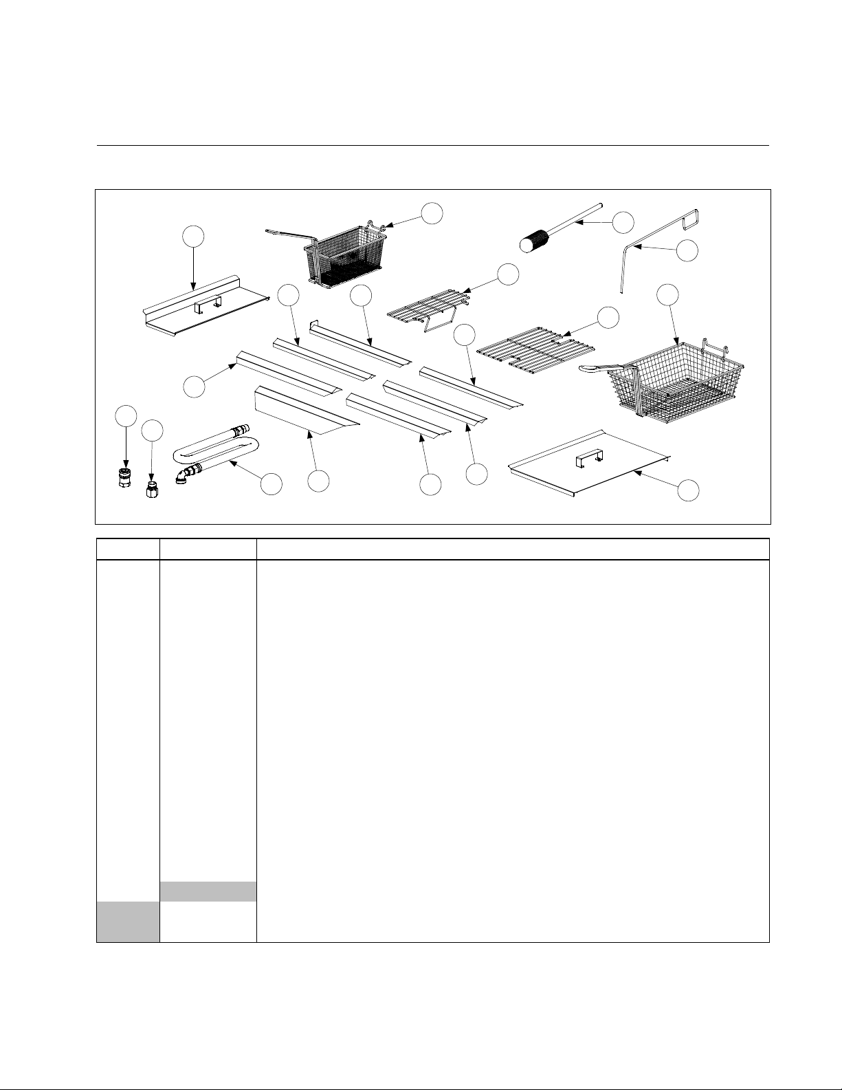
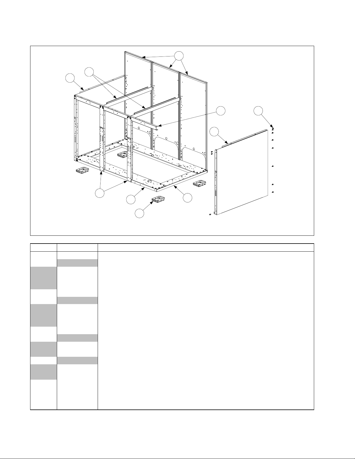
2.1 Accessories
H50 SERIES GAS FRYERS
CHAPTER 2: PARTS LIST
1
5
3
8
9
16
15
14
13
7
10
12
11
17
18
2
4
6
ITEM PART # COMPONENT
1 803-0271 Basket, Twin
2 803-0099 Basket, Full (cannot be used with basket lifts)
3 803-0133 Basket Support Rack, Dual Vat
4 803-0132 Basket Support Rack, Full Vat
* 803-0136 Basket Support Screen, Full Vat (screen w/handle used in place of Item 4)
5 806-3232 Cover, Frypot, Dual Vat
6 806-5518 Cover, Frypot, Full Vat
* 826-0993SP Handle Kit, Frypot Cover (includes handle and screws)
7 823-1885 Connecting Strip w/back plate (Burger King only)
8 910-4617 Connecting Strip (blunt point, ½” sides, 20.70” long) –Applebee’s Fryer to Filter
9 910-2285 Connecting Strip (blunt point, 1” sides, 20.80” long)- B.K. Wide
10 910-7515 Connecting Strip (sharp point, ½” sides, 21.73” long)- B.K. Dump Station to
Fryer, Also Applebee’s
11 910-7443 Connecting Strip (sharp point, 1” sides, 21.73” long)
12 910-7515 Connecting Strip (sharp point, 1” sides, 21.84” long)
13 910-2572 Connecting Strip (sharp point, 3” sides, 21.84” long)
14 Gas Line, 1-Inch Dormont Flexible (includes Items 15 and 16)
806-1698 36-Inch (for gas line only (w/o Items 15 and 16), use 810-0088)
806-1699 42-Inch (for gas line only (w/o Items 15 and 16), use 810-0085)
Continued on the following page
PDF compression, OCR, web optimization using a watermarked evaluation copy of CVISION PDFCompressor
2-1
Page 2

ITEM PART # COMPONENT
15 810-0074 Quick-Disconnect Fitting, 1-Inch Male
16 810-0073 Quick-Disconnect Fitting, 1-Inch Female
17 803-0209 Brush, Frypot Cleaning
18 803-0197 Fryer’s Friend 27” (Clean-out Rod)
* 910-3557 Flue Deflector
* 810-1306 Valve, Manual Gas Shut Off ½”
* 810-1307 Valve, Manual Gas Shut Off ¾”
* Not illustrated.
NOTE: Sediment Trays: 803-0103 (Full-Vat), 803-0107 (Left Dual-Vat), and 803-0108 (Right Dual-Vat)
PDF compression, OCR, web optimization using a watermarked evaluation copy of CVISION PDFCompressor
2-2
Page 3
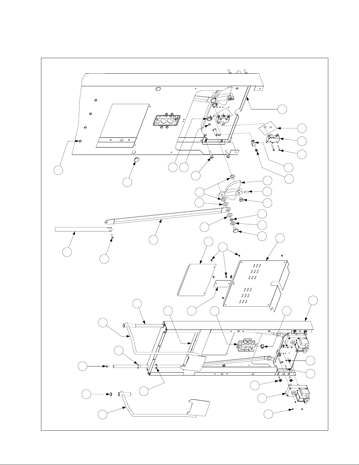
2.2 Basket Lift Assemblies and Component Parts
2.2.1 Bell Crank Basket Lifts
34
10 3 26
2
18
23
35
24
22
24
37
11
13
15
16
16
32
17
29
30
28
21
19
7
25
15
14
4
17
31
33
20
27
511
12
23
36
PDF compression, OCR, web optimization using a watermarked evaluation copy of CVISION PDFCompressor
9
2-3
5
1
6
Page 4

ITEM PART # COMPONENT
1 Gear Motor, Basket Lift
807-0107 120VAC
807-0108 240VAC
2 807-0124 Bushing, Plastic
3 807-0240 Microswitch
4 826-1680 Clamp, Plastic Wire (Pkg. of 8)
5 826-1358 Nut, 6-32 Hex (Pkg. of 25)
6 809-0050 Nut, 2-32 Hex
7 809-0063 Nut, Jam ⅜-16 Hex
8 809-0076 Nut, ¼-20 x ¾ Expansion
9 809-0082 Ring, Truarc Retaining
10 809-0097 Screw, 6-32 X 1-inch Slotted Truss Head
11 809-0113 Screw, 2-32 X 1½-inch Slotted Truss Head- Req 2 + 2 (809-0503 Motor Mounts)
12 809-0127 Screw, ¼-20 X ½-inch Slotted Round Head
13 826-1370 Screw, ¼-20 X 1¼-inch Slotted Round Head (Pkg. of 10)
14 809-0155 Leveling Screw
15 809-0196 Washer, ⅜-inch Steel Flat
16 826-1381 Washer, Nylon (Package of 10 each 809-0203)
17 809-0360 Screw, 2-32 X ⅜-inch Slotted Hex Washer Head
18 826-1374 Screw, 10 X ½-inch Hex Washer Head (Pkg. of 25)
19 809-0480 Setscrew, ¼-28 X ⅝-inch Hex Socket Head
20 810-0045 Bushing, Plastic
21 810-0052 Bellcrank and Cam
22 810-0170 Pin, Connecting
23 810-0172 Plug, ⅝-inch Hole S/S
24 810-0192 Rod, Basket Lift
25 810-0220 Spacer, Tubular
26 812-0138 Insulation, Paper (Fishpaper)
27 813-0035 Bushing, Bronze
28 823-1419 Box, Electrical Wiring
29 900-4110 Angle, Bearing Support
30 910-0119 Cover, Electrical Wiring Box
31 910-3177 Panel, Stainless Steel Rear Access (for mild steel, use 900-3177)
32 910-3783 Cover, Stainless Steel Rear Cabinet (for mild steel, use 900-3783)
33 910-9361 Housing, Basket Lift Stainless Steel (for mild steel, use 900-9361)
34 920-3233 Plate, Basket Lift Motor Mounting
35 920-6076 Link, Basket Lift
36 823-06931 Basket Lift Arm, Left
37 823-06932 Basket Lift Arm, Right
810-0172 Plug Button SS ⅝” Hole
* 806-2078 Wiring Harness, Basket Lift Power (6-pin male w/5 wires)
* 806-2079SP Wiring Harness, Basket Lift Motor (6-pin female w/7 wires)
* 806-7019SP Wiring Harness, Non-Modular Basket Lift (6-pin male & female w/5 wires)
* 807-2000 Wiring Harness, H50 B/L Connecting (15-pin male & female w/13 wires)
* 807-3695 Cable, H50 Basket Lift (15-pin male & 12-pin male w/6 wires) C2 to C4
* 807-2033 Cable, H50 Basket Lift (15-pin male & 6-pin male w/ 6 wires ) Older cable
* Not illustrated.
PDF compression, OCR, web optimization using a watermarked evaluation copy of CVISION PDFCompressor
2-4
Page 5
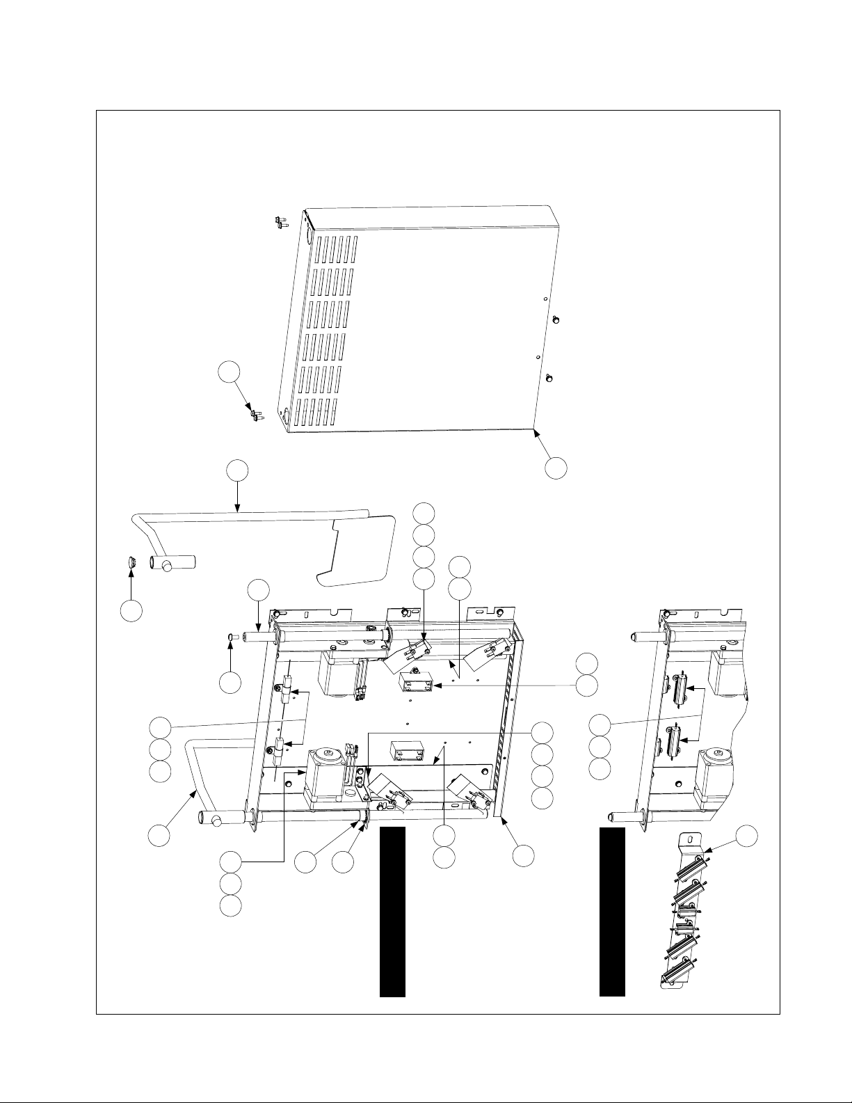
2.2.2 Modular Basket Lifts
14
25
4 10 12 18
17
16
8
20135
14 22
24
NOTES:
1. Assemblies 106-1807SP (100-120V) and 106-1810SP (208-250V) do not
include Items 8, 16, 24, 25, and 26. These items must be ordered separately.
2. For 100-120V units, each individual resistor (807-2661) may be replaced or
the entire reistor assembly (806-8530SP) may be replaced.
3. For 208-250V units, the entire resistor assembly (106-2771 or 806-9185) must
be replaced.
4. Wiring has been omitted for clarity.
3 13
2114117
12105
(Before 11/02)
26
6
1592
19
2314
1
5
(After 10/02)
100-120V Configuration
PDF compression, OCR, web optimization using a watermarked evaluation copy of CVISION PDFCompressor
2-5
208-250V Configuration
Page 6

ITEM PART # COMPONENT
1 Mount, Modular Basket Lift**
200-2942 For use on units with 12-pin connectors
900-7655 For use on units with 6-pin connectors
2 806-5964SP Motor Assembly, Modular Basket Lift
810-1013
3 807-2513
Gear, Modular Basket Lift (809-0504 Set Screw, 6-32 x .185)
Capacitor, 12.5 µFarad, 250VAC Motor Run
4 807-2572 Microswitch
5 Resistor Assembly
806-8530SP 100-120V Modular Basket Lift (see Note 2 in illustration) 807-2661 Resistor only
CE
106-2771 208-250V Modular Basket Lift (before 11/02 use 806-9185; see Note 3)
6 809-0082 Ring, Truarc Retaining
7 826-1361 Screw, 2-32 X 1-inch Slotted Truss Head (Pkg. of 25)
8 809-0127 Screw, ¼-20 X ½-inch Slotted Round Head
9 809-0186 Lock Washer w/External Teeth, #8
10 826-1366 Nut, 4-40 Hex Keps (Pkg. of 25)
11 809-0247 Nut, 2-32 Hex Keps
12 826-1359 Screw, 4-40 X ¾-inch Slotted Round Head (Pkg. of 25)
13 826-1371 Screw, #8 X ½-inch Hex Head Drill Point (Pkg. of 25)
14 826-1374 Screw, #10 X ½-inch Hex Head (Pkg. of 25)
15 809-0503 Screw, 2-32 X ½-inch Hex Head
16 810-0172
Plug, ⅝
inch Stainless Steel Hole
-
17 810-1012 Rod, Modular Basket Lift
18 812-0442 Insulation, Microswitch
19 813-0035 Bushing, Bronze, .640” ID
20 816-0033 Tie Wrap, Screw Mount
21 900-5529 Gusset, Modular Basket Lift Motor
22 901-8499 Chassis, Modular Basket Lift, Left
23 902-8499 Chassis, Modular Basket Lift, Right
24 910-4776 Cover, S/S Modular Basket Lift (for CRS cover use 900-4776)
826-1991 Cover, Kit S/S Modular Basket Lift with screws
25 823-06931 Arm Rod Assembly, Left Basket Lift
26 823-06932 Arm Rod Assembly, Right Basket Lift
*
Connector, Panel Mount**
807-0159 12-pin
807-0158 6-pin
Wire Assemblies**
* 806-9014SP For 100-120V Modular Basket Lift w/6-Pin Connector
* 806-8555SP For 202-250V Modular Basket Lift w/6-Pin Connector
* 106-1822SP For 100-120V Modular Basket Lift w/12-Pin Connector
* 106-1804SP For 202-250V Modular Basket Lift w/12-Pin Connector
Basket Lift Assemblies (see Note 1 in illustration)
* 106-1807SP 100-120V w/o Relay
* 106-1810SP 202-250V w/o Relay
** Not illustrated.
** Basket lift assemblies manufactured prior to February 2002 have 6-pin connectors; those manufactured February
2002 and later have 12-pin connectors. Verify the type of connector in use before ordering wiring assemblies or mounts.
PDF compression, OCR, web optimization using a watermarked evaluation copy of CVISION PDFCompressor
2-6
Page 7
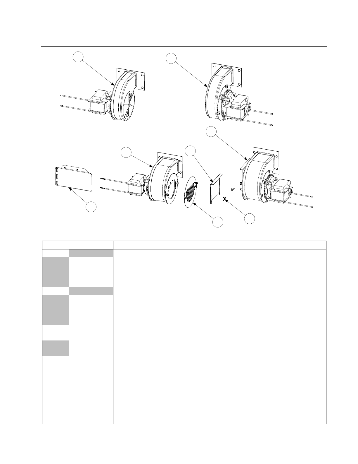
2.3 Blower Assemblies and Associated Components
1
3
8
2
4
6
5
7
ITEM PART # COMPONENT
1 Blower, Left (with 1.54-inch (3.91 cm) narrow housing)
106-2996SP 100V, 50/60 Hz
106-2994SP 115V, 50/60 Hz
806-5841SP 230V, 50 Hz
106-2995SP 240V, 50 Hz
2 Blower, Right (with 1.54-inch (3.91 cm) narrow housing)
806-4697SP 100V, 50/60 Hz
106-2997SP 115V, 50/60 Hz
807-7060SP 230V, 50 Hz
106-2998SP 240V, 50 Hz
3 106-3000SP Blower, Assembly Left, 230V, 50/60 Hz (with 2.2-inch (7.11 cm) wide hous-
ing) non-CE and CE
106-3002SP Blower, Assembly Left, 24V, 50/60 Hz (with 2.2-inch (7.11 cm) wide housing)
non-CE and CE
4 106-3001SP Blower, Assembly, Right 230V, 50 Hz (with 2.2-inch (7.11 cm) wide housing)
CE and non-CE
106-3003SP Blower, Assembly, Right 24V, 50 Hz (with 2.2-inch (7.11 cm) wide housing)
CE and non-CE
106-3000SP Blower Assembly, Left 230V, 50 Hz (CE)
5 806-9689 Finger Guard/Air Flow Inhibitor Adapter (CE)
6 900-8699 Air Flow Inhibitor (CE)
7 826-1382 Wingnut, 2-32 (Pkg. of 10)
8 826-1426 Shield, MH52 Blower Motor
Continued on the following page.
PDF compression, OCR, web optimization using a watermarked evaluation copy of CVISION PDFCompressor
2-7
Page 8

ITEM PART # COMPONENT
* 816-0554 Cover, Molded Plastic Blower Motor (fits left- or right-hand blowers)
* 809-0938
* 826-1383 Washer, ¼-inch Flat (for mounting blower to plenum) (Pkg. of 5)
* 826-1372 Nut, ¼-20 Hex (for mounting blowers to plenum) (Pkg. of 10)
* KIT-0155SP High Altitude Blower Kit (required above 5000 Ft, 1525 M)
* Not illustrated.
NOTES: Items 5, 6, and 7 are components of Items 3 and 4. In CE units, they replace the rotating air shut-
ter that is standard on 230V Blowers 106-3000SP and 106-3001SP (Items 3 and 4).
Blower Motor Cover P/N 816-0054 and Screw P/N 809-0938 are components of Items 1 through 4.
For Full Vat units, use Blower Assembly 106-2994SP (Non-CE) or 106-3000SP (CE). (Left Assembly.)
Some earlier CE units were built with blowers having housings 1.54 inches (3.91 cm) wide. Current
production CE-units are built with blowers having housings 2.71 inches (6.88 cm) wide. When ordering replacements for CE units, the width of the blower housing must be verified to ensure the correct
blower is provided.
CE units built before June 1999 were equipped with a blower shield that completely covered the
blower assemblies. This shield is no longer required and may be removed. The component parts of
the shield are no longer available for replacement.
Screw, 10-32 X ⅝ Philips Truss Head (secures Blower Motor Cover to motor)
PDF compression, OCR, web optimization using a watermarked evaluation copy of CVISION PDFCompressor
2-8
Page 9
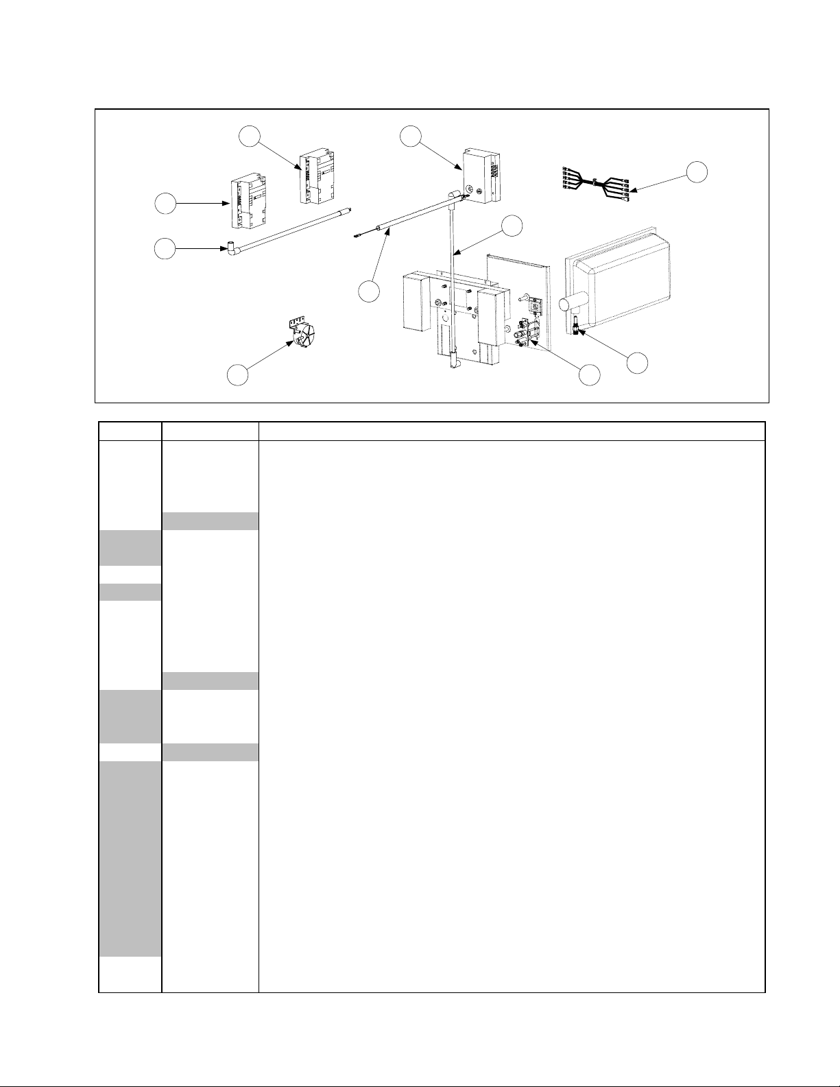
2.4 Burner Ignition System Components and Associated Hardware
2
3
5
6
8
1
7
4
10
9
ITEM PART # COMPONENT
1 See Pg 2-19 Ignition Module, Full and Dual Vat (original design, with fuse) 807-0910 Fuse
2 See Pg 2-19 Ignition Module, Full Vat (new design, without fuse)
* 826-1346 Spacer (Pkg. of 10)
3 See Pg. 2-19 Ignition Module, Dual Vat (new design, without fuse)
4 Ignition Cable
807-1878 19-inches long (with two 90º connectors, used with Item 1 only)
807-1200 27-inches long (with one 90º connector and one straight connector)
5 826-1721 Ignition Cable w/ Rajah (with one 90º connector, used with Items 2 and 3 only)
807-3483 Cable, Ignition 21” (807-3484 Rajah Connector Only)
6 806-6085SP Wire Assembly, Flame Sensor
7 806-6084SP Wiring Assembly, Ignition Module
8 807-2263
Switch, Air Pressure (use 807-2262 in units with 100VAC power supply)
* KIT1428 CE Export Air Switch Kit
9 Ignitor and Gasket Kit (816-0059 Gasket Only)
826-0981 Natural Gas (G20, G25)
826-0982 Propane/Butane (G30, G31)
826-1002 Manufactured Gas
10 Orifice
812-1137 1.95 mm Propane/Butane (G30, G31) (0-4999 Ft, 0-1524 M) (CE)
810-1221 2.00 mm Propane/Butane (0-4999 Ft, 0-1524 M) (Japan only)
810-0386 2.10 mm Propane/Butane (0-4999 Ft, 0-1524 M)
810-0413 2.16 mm Propane/Butane (G30, G31) (5000-6999 Ft, 1525-2133 M)
812-1028 2.20 mm Propane/Butane (G30, G31) (7000-10,999 Ft, 2134-3352 M)
812-1134 3.10 mm Natural Gas (G20, G25) (0-4999 Ft, 0-1524 M) (Japan only)
810-0403 3.40 mm Natural Gas (G20, G25) (0-4999 Ft, 0-1524 M)
810-0437 3.60 mm Natural Gas (G20, G25) (5000-6999 Ft, 1525-2133 M)
812-1144 3.65 mm Natural Gas (G20, G25) (7000-8999 Ft, 2134-2743 M)
812-1145 3.70 mm Natural Gas (G20, G25) (9000-10,999 Ft, 2744-3352 M)
810-0642 5.95 mm Manufactured Gas (0-4999 Ft, 0-1524 M)
* 826-1196 Conversion Kit, Natural Gas (G20, G25) to Propane/Butane (G30, G31)
* 826-1197 Conversion Kit, Propane/Butane (G30, G31) to Natural Gas (G20, G25)
* Not illustrated.
PDF compression, OCR, web optimization using a watermarked evaluation copy of CVISION PDFCompressor
2-9
Page 10
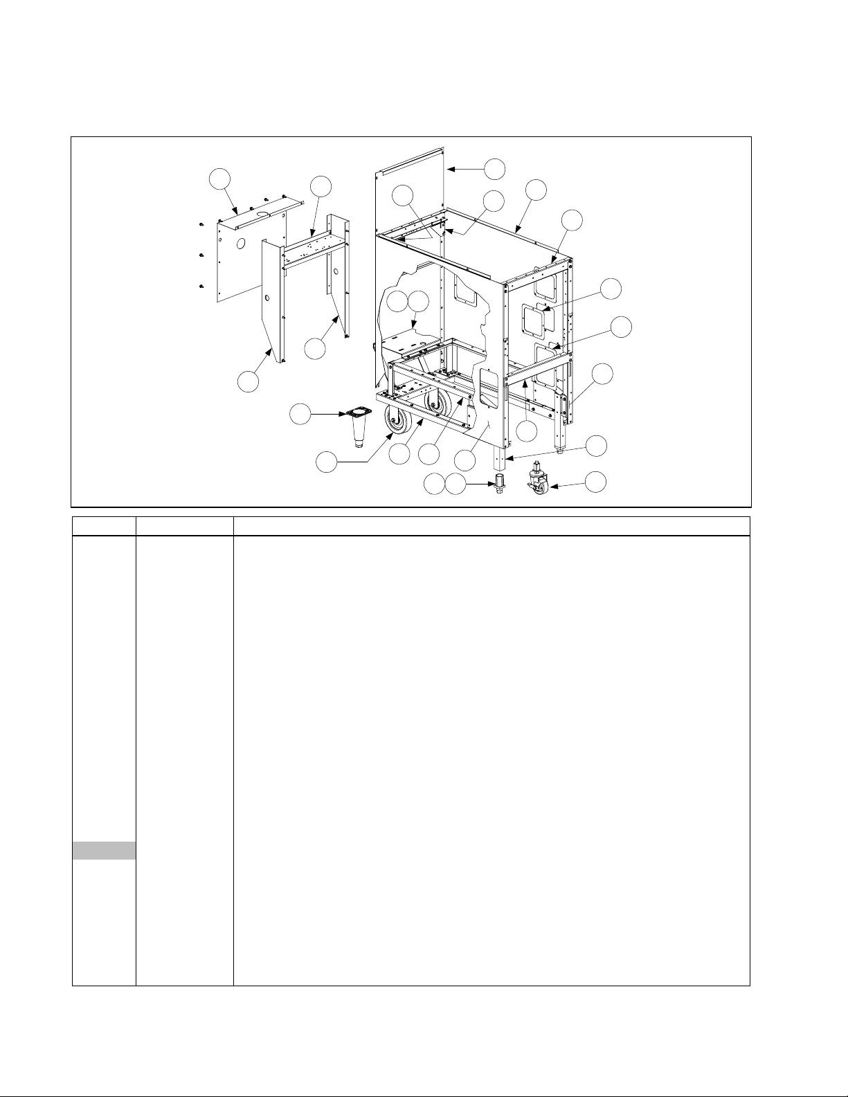
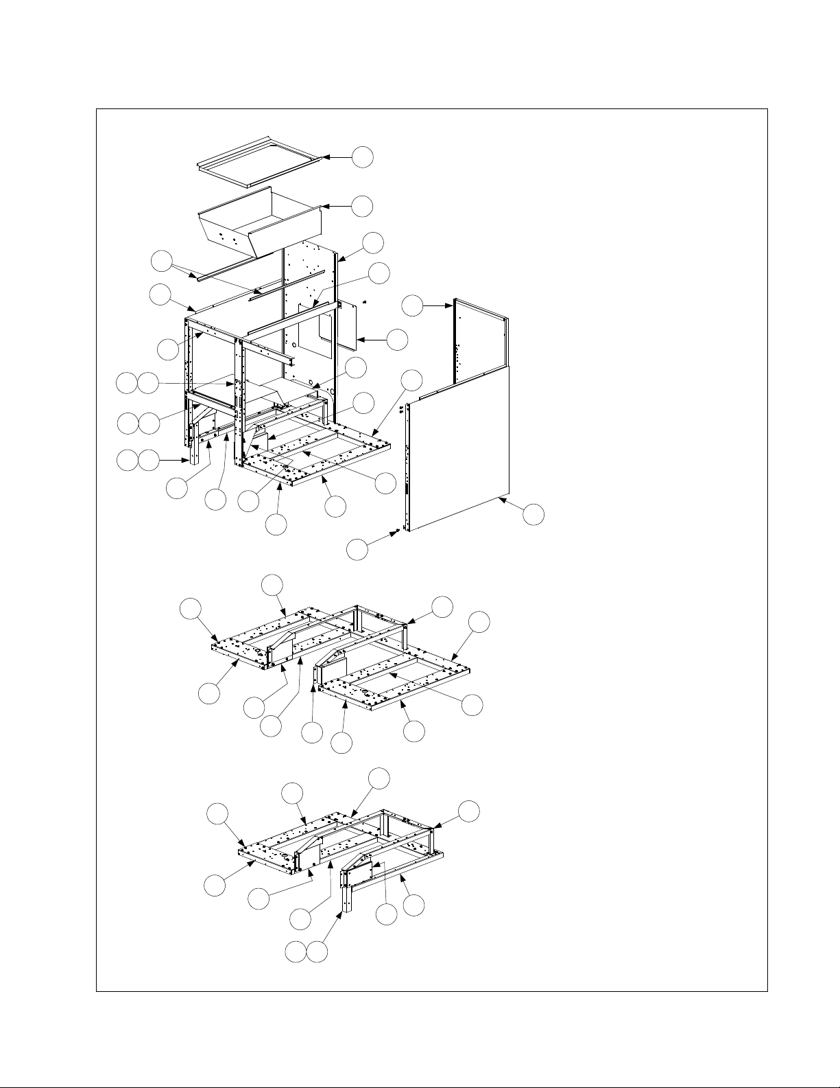
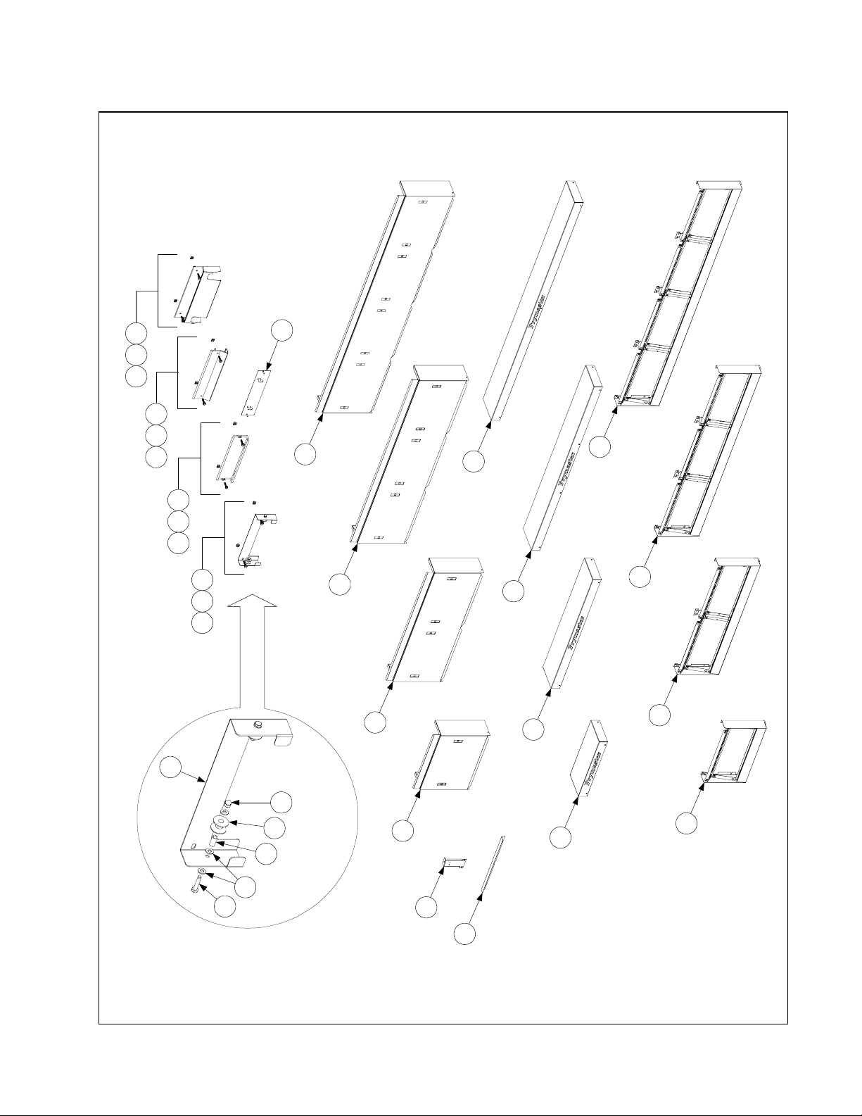
2.5 Cabinet Assemblies and Component Parts
2.5.1 FPH150 Cabinet Assembly
16
13
15
14
20
21
5
127
2
9
1
11
6
4
23
24
8
3
17
10
1918
22
ITEM PART # COMPONENT
1 900-7448 Back, Cabinet
2 806-4897SP Base Assembly (includes leg pad assembly 806-5209SP (see Page 2-13))
3 900-4391SP Brace, Cabinet, Front
4 900-4813SP Brace, Cabinet, Top
5 901-1405 Gusset, Left
6 902-1405 Gusset, Right
7 900-4551 Motor Mount
8 900-1621 Plate, Rail Mount (located inside lower front edge of Items 10 and 11)
9 806-5317SP Rail Assembly
10 911-9324
11 912-9324
Side, Cabinet, Stainless Steel, Left (use 901-9324SP for enameled cabinets)
Side, Cabinet, Stainless Steel, Right (use 902-9324SP for enameled cabinets)
12 900-1786 Support, Motor Mount
13 902-7447 Rear Extension, Right Side
14 901-7447 Rear Extension, Left Side
15 900-4555 Bracket, Transformer Mounting
16 900-4558 Cover, Rear Extension
17 910-1601
Leg, Filter Cabinet (use 910-8673 on units with rear casters (Item 20))
910-7925 Leg, 6” Single w/ Caster front (use w/ caster 823-2669) (White Castle)
18 810-0007 Leg, Adjustable (Inserts into Item 17)
19 910-1832 Retainer, Leg (Holds Item 18 in Item 17)
20 806-5043 Leg, 6 “ Adjustable
21 810-0750 Caster, 5” Rigid
22 823-2669 Caster, Single FootPrint front
23 910-0889
Cover, Access 5” x 5” SS for 4” x 4” Hole
(use 900-0889 for enameled cabinets)
24 910-0890 Cover, Access 5” x 7” SS for 4” x 6” Hole (use 900-0890 for enameled cabinets)
PDF compression, OCR, web optimization using a watermarked evaluation copy of CVISION PDFCompressor
2-10
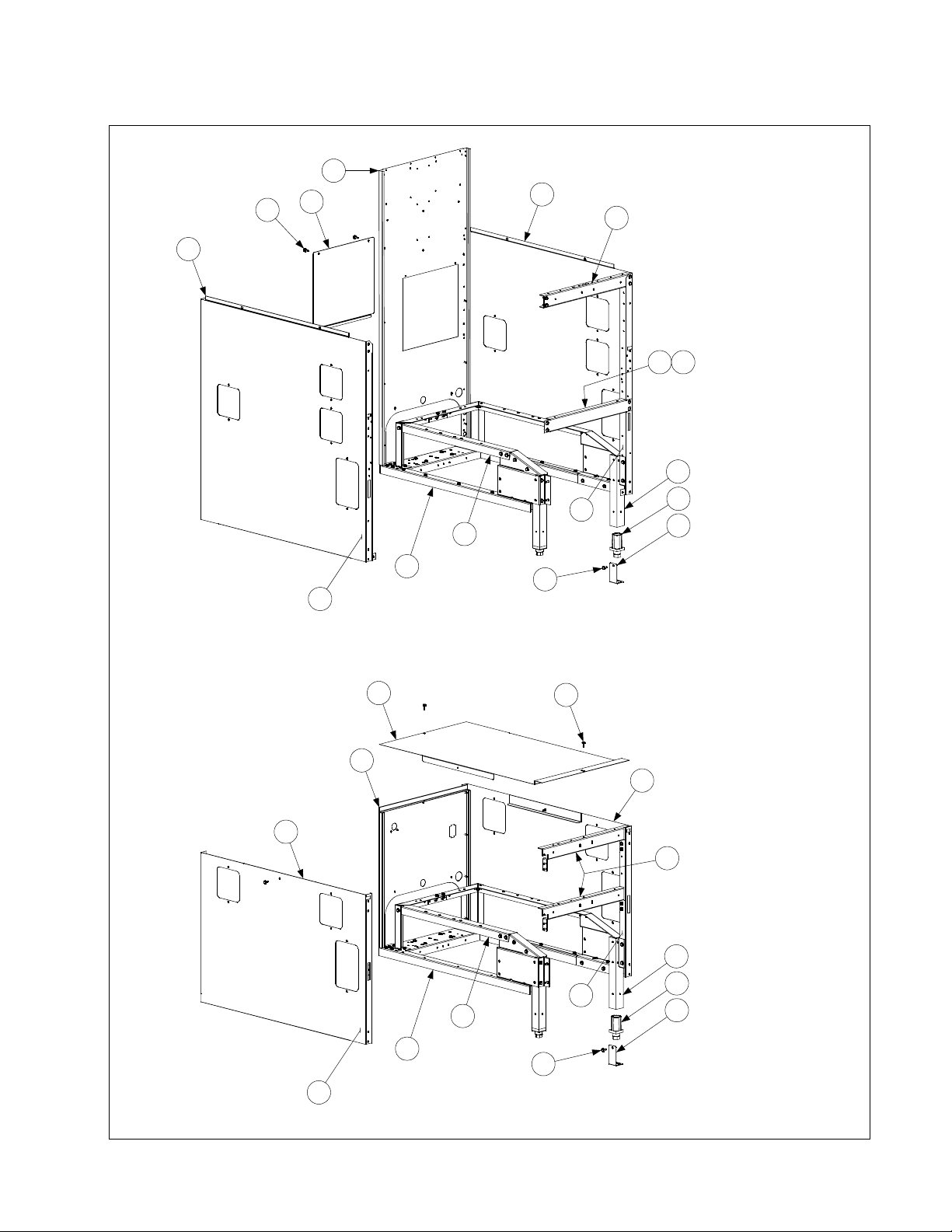
Page 11
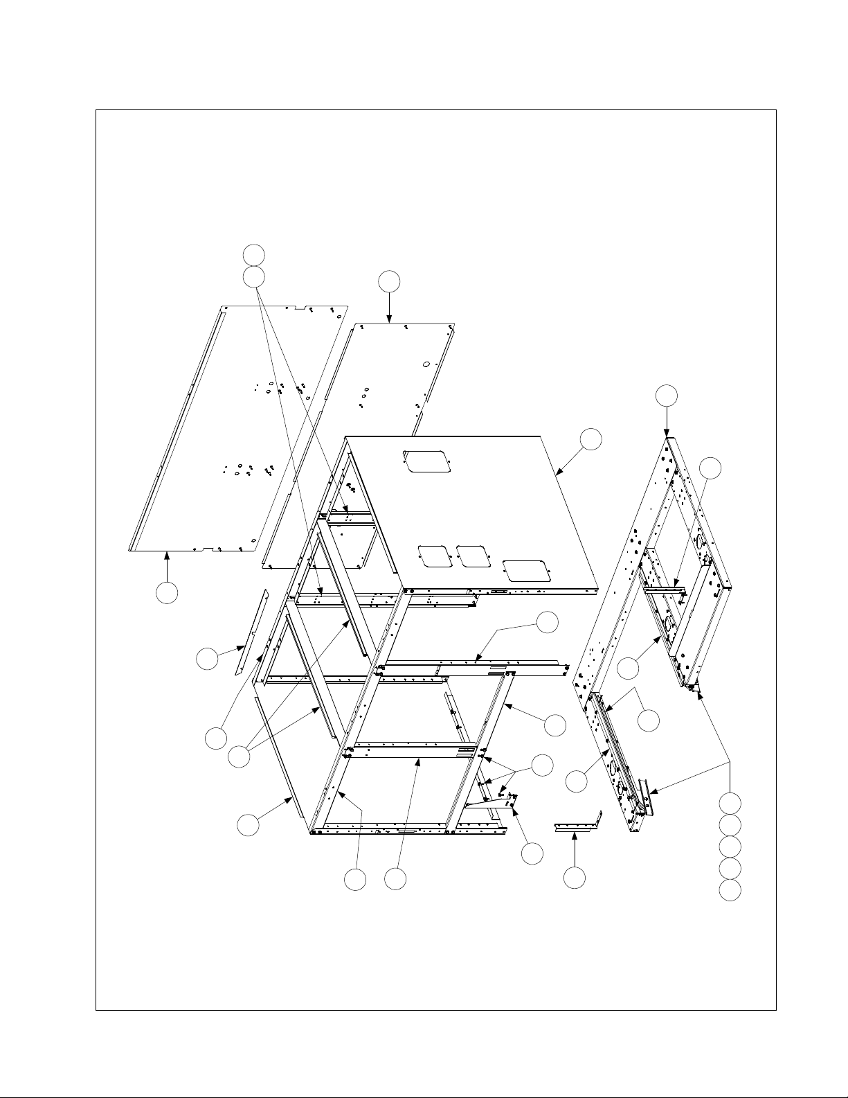
2.5.2 FPH50 Batteries
19 20
1
3
See Page 2-10 for acces s o p ening cove r s .
(FPH350 ILLUSTRATED IS TYPICAL OF ALL)
18
2
12
25
16
FPH50 MULTI-FRYER CABINET ASSEMBLIES
9
4
10
18
5
13
PDF compression, OCR, web optimization using a watermarked evaluation copy of CVISION PDFCompressor
2-11
6
21
15
11
8
17
242322127
Page 12

ITEM PART # COMPONENT
1 Back, Lower Cabinet
910-7657
910-9416
2 Back, Upper Cabinet
910-7658
910-9415
3 Base Assembly (includes leg pad assembly 806-5209SP (see Page 2-13))
806-5861SP FPH250
806-5862SP FPH350
806-7085SP FPH450
4 Brace, Cabinet Top, Rear
900-7327SP FPH250
900-9352 FPH350
900-2666SP FPH450
5 Brace, Cabinet Top, Front
900-7730SP FPH250
900-9430SP FPH350
900-9318 FPH450
6 900-7729 Brace, Cross Cabinet (not used on CE units)
7 900-1959 Bracket, Mounting
8 901-1948 Channel, Side Support, Left
9 902-1948 Channel, Side Support, Right
10 900-7326 Divider, Cabinet
11 901-1810 Gusset, Cabinet, Left
* 902-1810 Gusset, Cabinet, Right (used on FPH250 only)
12 900-1957 Lock, Filter
13 900-7734 Post, Door, Long
14 900-4773SP
15 911-4690 Rail, Filter, Top, Left
16 912-4690 Rail, Filter, Top, Right
17 910-5244 Rail, Filter, Universal
18 Side, Cabinet
910-7678SP Stainless Steel with no access openings
900-7678SP Enameled with no access openings
912-7679
902-7679SP
19 809-0413 Spacer, Nylon
20 900-4815 Support, Cabinet Rear
21 826-1374 Screw, #10 X ½-inch Hex Washer Head (Pkg. of 25)
22 809-0422 Screw, 10-32 X 7/16-inch Slotted Truss Head
23 809-0189 Washer, ¼-inch Flat
24 809-0053 Nut, 10-32 Hex
25 900-4253 Flueclip Retainer
* 901-4314 Heat Shield Left
* 902-4315 Heat Shield Right
* 900-4833 Heat Shield Center
* Not illustrated.
FPH250/FPH450 Stainless Steel (use 900-7657 for aluminized steel)
FPH350 Stainless Steel (use 900-9416 for aluminized steel)
FPH250/FPH450 Stainless Steel (use 900-7658 for aluminized steel)
FPH350 Stainless Steel (use 900-9415 for aluminized steel)
Post, Door, Short (use 900-2567 on CE units)
Stainless Steel with access openings (used on Filter Ready units only)
Enameled with access openings (used on Filter Ready units only)
Component Heat Shields
PDF compression, OCR, web optimization using a watermarked evaluation copy of CVISION PDFCompressor
2-12
Page 13
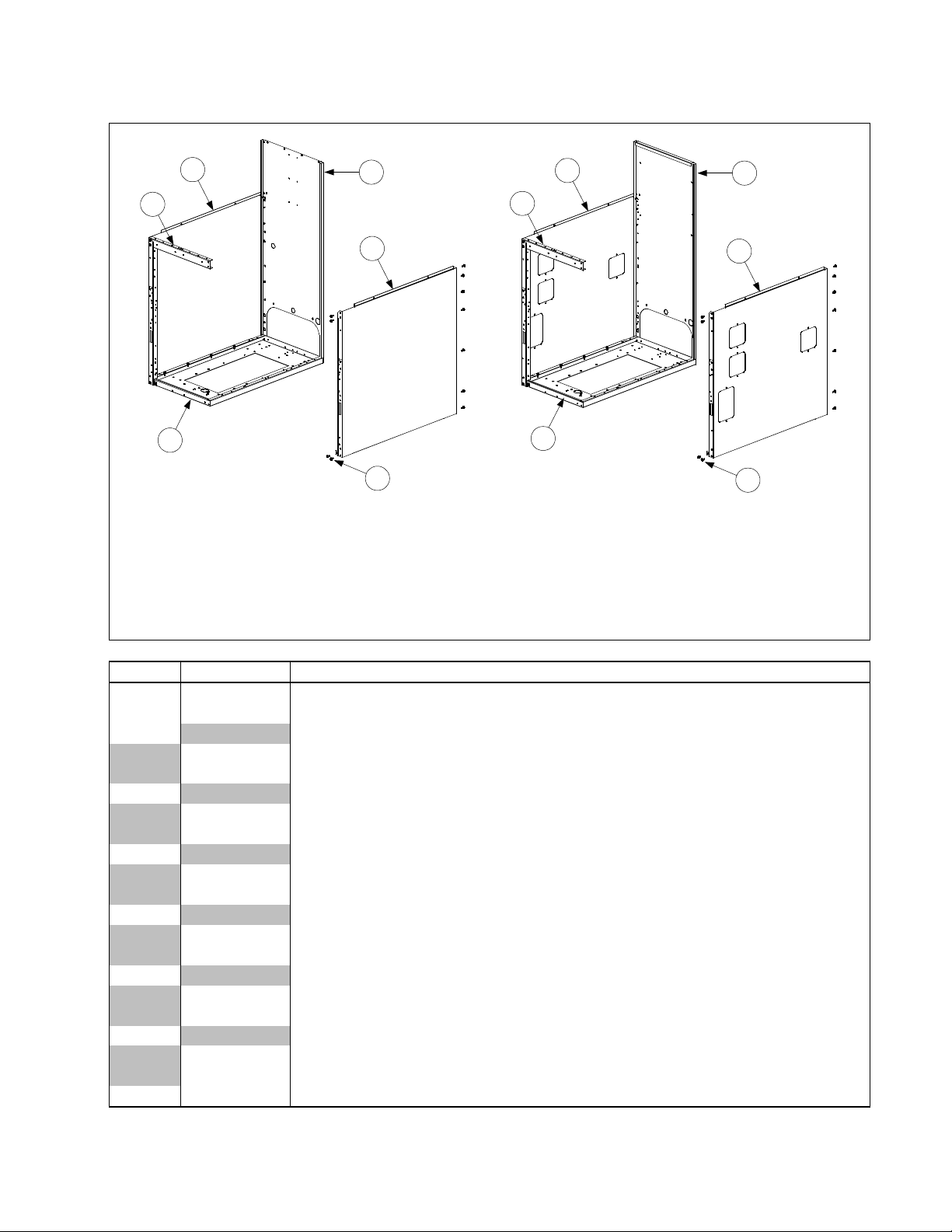
2.5.3 FH150, MJH150, and Spreader Cabinets
5
2
Spreader Cabinet
1
(Typical)
3
6
9
7
2
Fryer Cabinet
1
(Typical)
See Page 2-10 for
access opening covers.
4
8
9
NOTES: Complete Spreader Cabinet Assemblies are : 806-6495SP (S/S) and 806-6496SP (CR).
Complete Fryer Cabinet Assemblies are: 806-46232SP (S/S) and 806-46231SP (CR).
Fryer and spreader cabinet assemblies are identical e xcept for the backs — spreader b acks do
not have a formed edge at the top. Cabinet sides wit h acces s openings ar e used on FH1 50 units
or on spreader cabinets placed in batteries of fryers equipped with built-in filtration systems.
ITEM PART # COMPONENT
1 900-2568SP Base, Cabinet, One-Piece
2 900-4813SP Brace, Cabinet Top
3 Back, Spreader Cabinet
910-6983SP Stainless Steel
900-6983SP Aluminized Steel
4 Back, Fryer Cabinet
910-7213SP Stainless Steel
900-7213SP Aluminized Steel
5 Side, Left Cabinet w/o Access Openings
911-9323SP Stainless Steel
901-9323SP Enameled
6 Side, Right Cabinet w/o Access Openings
912-9323SP Stainless Steel
902-9323SP Enameled
7 Side, Left Cabinet w/Access Openings
911-9324SP Stainless Steel
901-9324SP Enameled
8 Side, Right Cabinet w/Access Openings
912-9324SP Stainless Steel
902-9324SP Enameled
9 826-1374 Screw, #10 X ½-inch Hex Washer Head (Pkg. of 25)
PDF compression, OCR, web optimization using a watermarked evaluation copy of CVISION PDFCompressor
2-13
Page 14
2.5.4 MJH50 Batteries
9
6
8
7
3
2
5
1
MJH50 MULTI-FRYER CABINET ASSEMBLIES
(MJH350 ILLUSTRATED IS TYPICAL OF ALL)
ITEM PART # COMPONENT
1 900-4426SP Channel, Left and Right Side
2 Channel, Front and Rear
900-2395SP Double
900-2396SP Triple
900-9373 Quad
3 900-6979SP Post, Door
4 Brace, Cabinet Top
900-7730SP Double
900-9430SP Triple
900-9318 Quad
5 806-5209SP Leg Pad Assembly
6 Side, Left Cabinet
911-9323SP
901-9323SP
Stainless Steel (use 911-9324SP for side with access openings)
Enameled (use 901-9324SP for side with access openings)
7 Side, Right Cabinet
912-9323SP
902-9323SP
Stainless Steel (use 912-9324SP for side with access openings)
Enameled (use 902-9324SP for side with access openings)
8 900-6983SP Back, Cabinet
9 900-7326 Divider, Cabinet
10 826-1374 Screw, #10 X ½-inch Hex Washer Head (Pkg. of 25)
* 826-1494 Kit, Jack in the Box Filter Magic Cold Air Block
* Not illustrated.
4
10
PDF compression, OCR, web optimization using a watermarked evaluation copy of CVISION PDFCompressor
2-14
Page 15
2.5.5 FMH50 Batteries with Built-In Filtration
1
2
NOTE: It ems 1-1 5 are used i n
all FMH50 Builit-In Filter
configurations and therefore are
4
3
7
22
1110
1312
15
6
5
9
28
20
not repeated for the F MH250
and FMH150 (Filter o n Right)
illustrations.
FMH150 (FILTER ON LEFT)
(All components except Items 27 and
28 are the same for FMH250 a nd
FMH350 units wit h the fi l ter on the
1716
18
22
14
27
25
29
25
26
8
29
(See Page 2-14 for Leg Pad Assembl y )
24
28
left.)
FMH250 (FILTER BETWEEN FRYERS)
(All components except Items 27 and 28
are the same for FMH350 cabinets with
27
19
26
20
27
25
26
the filter between fryers.)
28
25
29
24
FMH150 (FILTER ON RIGHT)
(All components except Items 27 and 28
are the same for FMH250 and FMH350
27
PDF compression, OCR, web optimization using a watermarked evaluation copy of CVISION PDFCompressor
19
26
1716
23
21
2-15
units with the filter on the right.)
Page 16

ITEM PART # COMPONENT
1 910-7480 Trim, Filter Cabinet Top
2 806-8274SP Pan Assembly, Filter/Spreader Cabinet
3 900-7277 Support, Drain Pan
4 Back w/Access Opening, Filter Cabinet
910-7274SP Stainless Steel
900-7274SP Aluminized Steel
5 900-4089 Cover, Cabinet Back Access
6 Back, Cabinet
910-6983SP Stainless Steel
900-6983SP Aluminized Steel
7 Side, Left Cabinet
911-9323SP Stainless Steel
901-9323SP Enameled
8 Side, Right Cabinet
912-9323SP Stainless Steel
902-9323SP Enameled
9 900-7414 Shield, Filter Magic Pan
10 900-6979SP Post, Door
11 809-0413 Spacer, .25 x .160 8 Gauge Nylon (located behind Item 10 at bottom)
12 900-4391SP Brace, Front Cabinet
13 826-1379 Screw, #10 x ½-inch Philips Truss Head (package of 10)
14 900-1700 Bracket, Drain Support
15 900-7314SP Divider, Cabinet
16 910-1601 Leg, Filter
17 900-1621 Plate, Rail Mount (located inside front edge of Item 7)
18 901-1599 Bracket, Left Pan Rail (used on cabinets with filter on left)
19 901-1595 Bracket, Left Pan Rail (used on cabinets with filter on right or in middle)
20 902-1599 Bracket, Right Pan Rail (used on cabinets with filter on right or in middle)
21 902-1595 Bracket, Right Pan Rail (used on cabinets with filter on right)
22 901-4390 Channel, Left Filter Side
23 902-4390 Channel, Right Filter Side
24 806-4917 Rail Assembly, Filter Magic
25 900-4426 Channel, Fryer Outside
26 900-4383 Channel, Fryer Inside
27 Channel, Fryer Front
900-2394 Single Fryer
900-2395 Double Fryer
900-2396 Triple Fryer
28 Channel, Filter Magic Cabinet Rear
900-1631 FMH150 Filter Left
900-7243 FMH250 Filter Left
900-9319 FMH350 Filter Left
900-1630 FMH150 Filter Right
900-7244 FMH250 Filter Right
900-9322 FMH350 Filter Right
900-7242 FMH250 Filter Middle
900-9321 FMH350 (Fryer, Fryer, Filter, Fryer)
900-9320 FMH350 (Fryer, Filter, Fryer, Fryer)
29 826-1374 Screw, #10 X ½-inch Hex Washer Head (Pkg. of 25)
PDF compression, OCR, web optimization using a watermarked evaluation copy of CVISION PDFCompressor
2-16
Page 17
2.5.6 Filter Magic Add-On Cabinetry
3
18
1
4
12
13
14
2
14
18
NOTE: Items 1-3 and 9
from Page 2-16, and Item
20 or 21 from Page 2-10
9
are also used in this
cabinet.
10 19
15
16
17
ADD-ON
FILTER MAGIC CABINET
NOTE: Item 9 from Page
2-16, and Item 20 or 21
from Page 2-10 are also
used in this cabinet.
5
See Page 2-10 for access opening covers.
8
7
12
13
18
14
18
6
11
15
16
17
UNDERCOUNTER ADD-ON
FILTER MAGIC CABINET
14
PDF compression, OCR, web optimization using a watermarked evaluation copy of CVISION PDFCompressor
2-17
Page 18

ITEM PART # COMPONENT
1 Side, Left Cabinet, w/Access Openings
911-9324SP Stainless Steel
901-9324SP Enameled
2 Side, Right Cabinet, w/Access Openings
912-9324SP Stainless Steel
902-9324SP Enameled
3 Back w/Access Opening, Filter Cabinet
910-7274SP Stainless Steel
900-7274SP Aluminized Steel
4 900-4089 Cover, Cabinet Back Access
5 Side, Left Undercounter Cabinet
911-7677SP Stainless Steel
901-7677SP Enameled
6 Side, Right Undercounter Cabinet
912-7677SP Stainless Steel
902-7677SP Enameled
7 Back, Undercounter Cabinet
910-4786 Stainless Steel
900-4786 Aluminized Steel
8 910-7680 Cover, Undercounter Cabinet
9 900-4813SP Brace, Cabinet Top
10 900-4391SP Brace, Cabinet Front
11 900-4785 Brace, Undercounter Cabinet Top and Center
12 806-5317SP Rail Assembly
13 806-4897SP Base Assembly (includes leg pad assembly 806-5209 (see Page 2-13))
14 900-1621 Plate, Rail Mount (located inside lower front edge of Items 1, 2, 5, and 6)
15 910-1601
16 810-0007 Leg, Adjustable
17 910-1832 Retainer, Leg Insert, Full Height
18 826-1374 Screw, #10 X ½-inch Hex Washer Head (Pkg. of 25)
19 826-1379 Screw, #10 X ½-inch Philips Truss Head (Pkg. of 10)
* 910-8503 Front Panel HE Filter Magic
* 802-0391 Label, FMII Control Panel
* 900-8906 Liner, Floor One Piece Base
* 901-1599 Bracket, Left Pan Rail Leg
* 902-1599 Bracket, Right Pan Rail Leg
* 910-0889 Cover, 4” Cabinet Side Hole S/S
* 910-0890 Cover, 7” Cabinet Side Hole S/S
* Not illustrated
Leg, Filter Cabinet (use 910-8673 on units with rear casters)
PDF compression, OCR, web optimization using a watermarked evaluation copy of CVISION PDFCompressor
2-18
Page 19
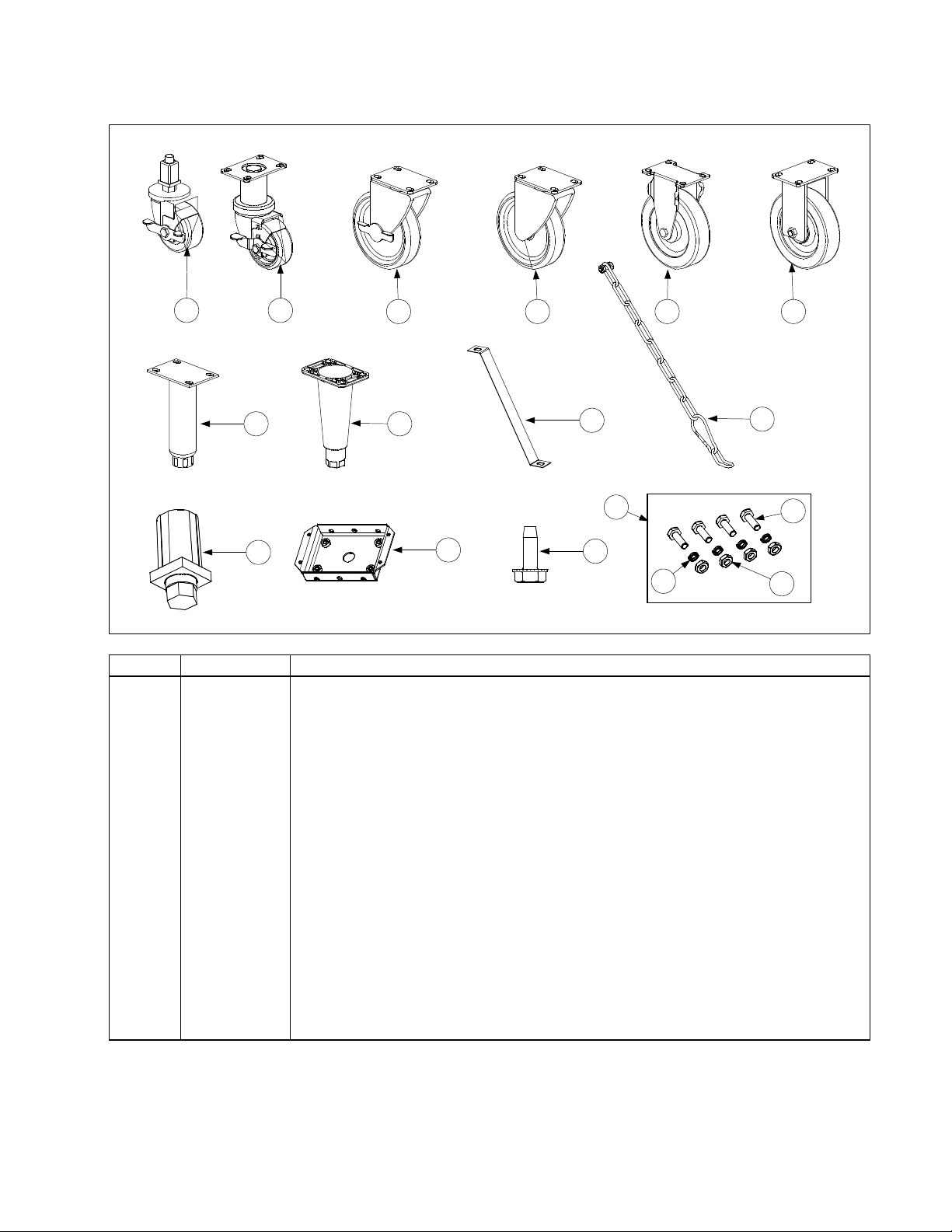
2.6 Casters, Legs, and Restraints
1 2
7 8
11
3 5 6
12
4
9
14
13
ITEM PART # COMPONENT
1 823-2669 Caster, Single FootPrint Front
* 910-7925 Mounting Leg for Caster 823-2669
2 826-1130 Caster, 3” Swivel w/Brake (810-0651)
3 826-1118 Caster, 5” Swivel w/Brake (810-0357)
4 826-1117 Caster, 5” Swivel w/o Brake (810-0356)
5 826-1138 Caster, 5” Rigid w/o Brake (810-0378)
6 826-1114 Caster, 5” Rigid w/o Brake (810-0750)
7 826-1237 Leg Assembly, Stainless Steel (810-1205)
8 826-1115 Leg Assembly, Nickel Plated (806-5043)
9 826-1095 Anchor Strap Kit (for use on single fryers w/legs)
10 826-0900 Chain Restraint Kit (for use on fryers w/casters)
11 810-0007 Leg, Square Tube
12 806-5209SP Leg Pad (mounts with 826-1374)
13 826-1374 Screw, #10-1/2 HX Washer HD NP
14 826-1113 Caster Fastener Kit (One Caster)
15 826-1389 Screw, Hex Head ¼-20 x ¾
16 809-0191 Washer, ¼ Lock Spring ZP
17 826-1362 Nut, ¼-20 Hex
10
15
16
17
NOTE: Items 2 through 8 include 1 caster or leg, 4 mounting bolts, and 4 lock washers.
PDF compression, OCR, web optimization using a watermarked evaluation copy of CVISION PDFCompressor
2-19
Page 20
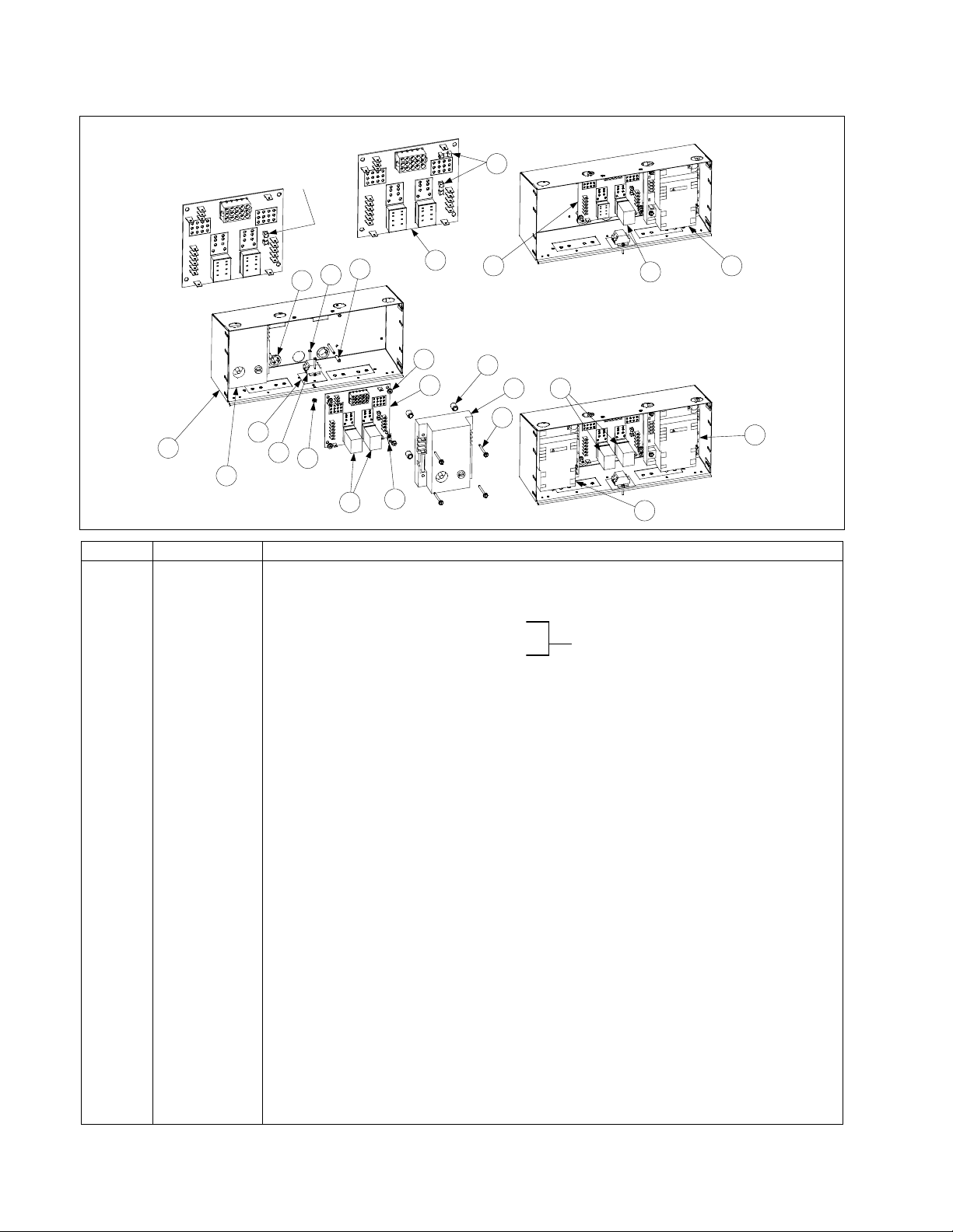
2.7 Component Box Assemblies and Associated Component Parts
)
y)
)
p
p
)
y)
p
)
g)
)
)
)
)
)
)
)
)
d
)
y)
IFB 806-3398 (Discontinued) has only one
fuse. If used with 807-3365 or 807-3366
modules, an in-line fuse should be added
between the module and the board.
Replaced by 106-0386
IFB 106-0386 (Item 7) has two
fuses and may be used with any
of the ignition modules.
6
13
11
8
9
1
2
10
12
5
7
14
6
15
7
Full vat units using one 807-3366 module
(Item 3) require only one latch relay (Item 5).
Full or dual vat units using two 807-1006,
807-2971, or 807-3365 modules require a
latch rel ay (I tem 5) for eac h mo dul e.
16
2
5
17
5
4
3
4
ITEM PART # COMPONENT
1 200-5996 Box Assembly, One-Piece Component
2 807-1006 Ignition Module, Full or Dual Vat (fuse-protected
* 807-2971 Ignition Module, Full or Dual Vat (fuse-protected) (Australian units onl
3 807-3366 Ignition Module, Full Vat (unfused
4 807-3365 Ignition Module, Dual Vat (unfused) use 1 wire 1 connector ign. cable 826-2024
5 807-0833 Relay, 12V 5Am
* 807-0834 Relay, 12V 5Am
Latch (use Relay Clip 810-2243 to secure relay in place)
Basket Lift (use Relay Clip 810-2243 to secure relay in place)
6 807-3843 Fuse, 3A 250V Subminature
7 106-0386 Interface Board (double fuse-protected)(use w/ 807-3365, 807-1006 or 807-3366
* 806-4973 Interface Board (used with 240V manufactured gas units onl
* 806-3683 Interface Board (used with Ger. fryers with 24V blowers only) use 5A fuse 807-3293
* 106-3044 Interface Board, FAST Com
uter (uses 807-3969 latch relay in place of Item 5)
* 806-3641 Interface Board, (used in Holland
* 806-4195SP Interface Board, (used with manufactured gas Hong Kon
* 806-3535 Interface Board, (used in Churches w/ Far West Computers
8 807-1926 Bushing, .875 Diameter Split
9 816-0217 Paper, Insulating (Items 9, 10, 11, 12 not used on Hong Kong units
10 810-1164 Block, Terminal (See Item 9
11 826-1359 Screw, 4-40 x ¾-inch Slotted Round Head (See Item 9) (Pkg. of 25
12 826-1366 Nut, 4-40 Keps Hex (See Item 9) (Pkg. of 25
13 807-1241 Spacer, Interface Board (.151-inch ID x ⅝-inch
14 809-0250 Nut, 6-32 Keps Hex
15 826-1337 Tab, Push-On Terminal (Pkg. of 5
16 826-1346 Spacer, Ignition Module (.260-inch ID x ½-inch) (Pkg. of 10
17 809-0441 Screw, #7 x 1½-inch Slotted Washer Hex Hea
* 826-1157 Fuse Kit, Ignition Module 3 Amp (fuse and fuse puller
* 806-2071 Computer Cable 15-pin
* 806-3660
Sound Device (For units with KFC1 Computers, use Speaker 807-1617)
* 807-1359 Mount, Tie-Wrap (used on CE units onl
* Not illustrated.
PDF compression, OCR, web optimization using a watermarked evaluation copy of CVISION PDFCompressor
2-20
Page 21
2.8 Control Panel Assemblies, Flue Caps, Top Caps, and Related Components
653
652
651
657
4
17
16
15
23
22
21
27
26
25
8
13
12
11
10
9
PDF compression, OCR, web optimization using a watermarked evaluation copy of CVISION PDFCompressor
14
18
19
20
2-21
24
Page 22

ITEM PART # COMPONENT
1 810-2793 Basket Hanger, Wire Form
2 803-0028 Basket Hanger, Extruded Aluminum (replaced by 810-2793)
3 823-1462 Basket Hanger, Burger King
* 106-2186 Basket Hanger Assembly, Burger King (includes Items 1, 4 and 13)
4 106-2185 Bracket, Burger King Easy-Off Basket Hanger (used w/Item 1)
5 809-0171
* 809-0921 Spacer, Basket Hanger
6 826-1351 Nut, Cage (receives Basket Hanger Thumbscrew) (Pkg. of 10)
7 806-9257SP Roller Assembly, Basket Lift (Complete)
8 910-8284 Bracket, One-Piece Roller Guide
9 826-1334 Capscrew, ¼ – 20 x 1¼” Stainless Steel Hex Head (Pkg. of 5)
10 809-0190 Washer, ¼” Stainless Steel Flat
11 810-0374 Spacer, Tubular
12 810-0194 Roller, Basket Lift Guide
13 809-0047 Nut, ¼ – 20 Cap (also used w/Item 4)
14 Flue Cap, Single Fryer, w/lip
910-5018 Standard (use 910-5019 on Burger King fryers)
910-6545 Optional (without lip along flue opening)
823-3749 Burger King with Button Studs (used w/Item 4)
15 Flue Cap, 2-Fryer Battery
823-2540 Standard (use 823-2542 on Burger King fryers)
823-3536 Burger King with Button Studs (used w/Item 4)
16 Flue Cap, 3-Fryer Battery (use 823-2543 on Burger King fryers)
823-2541 Standard (use 823-2543 on Burger King fryers)
823-3537 Burger King with Button Studs (used w/Item 4)
17 823-2569 Flue Cap, 4-Fryer Battery
823-3538 Burger King with Button Studs (used w/Item 4)
18 900-5486 Support, Flue Cap
19 900-4253 Flue Cap Retaining Strip, Burger King
* 910-3557 Flue Deflector
20 Top Cap, Single Fryer
824-0404 Standard
824-0408 H50 side of H50/FB18 Battery
21 824-0405 Top Cap, Two-Fryer Battery
22 824-0406 Top Cap, Three-Fryer Battery
23 824-0407 Top Cap, Four-Fryer Battery
24 Control Panel Assembly, Single Fryer
806-4732SP Standard (see Note 1)
806-5363SP H50 side of H50/FB18 Battery
25 806-4733SP Control Panel Assembly, 2-Fryer Battery (see Note 2)
26 806-4734SP Control Panel Assembly, 3-Fryer Battery (see Note 3)
27 806-5018SP Control Panel Assembly, 4-Fryer Battery (see Note 4)
* 826-1379 Screw, #10 X ½-inch Philips Head (Pkg. of 10) (attaches top cap)
* 826-1371 Screw, #8 X ½-inch Hex Washer Head (Pkg. of 25) (attaches flue cap)
* Not illustrated.
NOTES:
1. Use 806-9712SP on KFC fryers; use 106-2927SP for units with fallback controllers.
2. Use 806-9713SP on KFC fryers; use 106-2928SP for units with fallback controllers.
3. Use 806-9714SP on KFC fryers; use 106-2929SP for units with fallback controllers.
4. Use 806-9715SP on KFC fryers.
Thumbscrew, ¼-20 X 1⅜-inch Basket Hanger
PDF compression, OCR, web optimization using a watermarked evaluation copy of CVISION PDFCompressor
2-22
Page 23

2.9 Controller Assemblies
2.9 Controller Assemblies
1 2 3
ITEM PART # COMPONENT
ITEM
1 Computer Magic III
2 Basket Lift Timer
2 Basket Lift Timer
3 Digital Controller
3 Digital Controller
4
4
I
I
*
* 106-0613 CM4-S Computer (CE)
*
* 806-4323 Fallback Controller Assembly
Continued on the following page
Continued on the following page
PART #
Computer Magic III
106-1 187SP Dual Vat (CE)
106-1187SP Dual Vat (CE)
106-1151 SP Dual Vat (Non-CE)
106-1151SP Dual Vat (Non-CE)
106-1 155 SP Dual Vat w! 8 sec. Melt Cycle
106-1155SP Dual Vat w/ 8 sec. Melt Cycle
106-1 1885P Full Vat (CE)
106-1188SP Full Vat (CE)
106-1 1505P Full Vat (Non-CE)
106-1150SP Full Vat (Non-CE)
106-12 16
106-1216 Full Vat, Remote BK on the Hood
106-1226 Full Vat, Remote BK in the Hood
106-1226 Full Vat, Remote BK in the Hood
106-20815P Dual Vat (CE)
106-2081SP Dual Vat (CE)
106-20745P Dual Vat (Non-CE)
106-2074SP Dual Vat (Non-CE)
106-2077SP Full Vat (CE)
106-20775P Full Vat (CE)
106-2073 SP Full Vat (Non-CE)
106-2073SP Full Vat (Non-CE)
826-1552 Kit, 120v Push Button 15 min timer retrofit
826-1552 Kit, 120v Push Button 15 min timer retrofit
826-1667 Kit, 240v Push Button
826-1667 Kit, 240v Push Button
106-15065P Dual Vat (CE)
106-1506SP Dual Vat (CE)
106-15 10 Dual Vat (Non-CE)
106-1510 Dual Vat (Non-CE)
106-1505 SP Full Vat (CE)
106-1505SP Full Vat (CE)
106-15095P Full Vat (Non-CE)
106-1509SP Full Vat (Non-CE)
806-3564E Dual Vat (CE) w! 8 sec. Melt Cycle
806-3564E Dual Vat (CE) w/ 8 sec. Melt Cycle
806-3008E Dual Vat (Non-CE)
806-3008E Dual Vat (Non-CE)
806-3563E Full Vat (CE) w! 8 sec. Melt Cycle
806-3563E Full Vat (CE) w/ 8 sec. Melt Cycle
806-3006E
806-3006E
106-06 13 CM4-S Computer (CE)
Full Vat, Remote BK on the Hood
Solid State (Analog) Controller (Controller Knob is 810-0387)
Solid State (Analog) Controller (Controller Knob is 810-0387)
Full Vat (Non-CE) (for Foodmaker units, use 806-7385)807-223 6 Overlay
Full Vat (Non-CE) (for Foodmaker units, use 806-7385)807-2236 Overlay
806-4323 Fallback Controller Assembly
COMPONENT
4
SOLID STATE
PDF compression, OCR, web optimization using a watermarked evaluation copy of CVISION PDFCompressor
2-23
Page 24

2.9 Controller Assemblies cont.
ITEM PART# COMPONENT
* 806-5300
KFC1 Computer (requires special control panel assembly – see Page 2-22)
* 826-1032SP Kit, Bezel Screw and Tinnerman Clip (contains two screws and two clips)
* 826-1379 Screw, #10 X ½-inch Philips Truss Head (computer screws) (Pkg. of 10)
* 910-3690
Blank Panel (for fryers with remote mounted computers)
* 806-2071 Harness, Main Short Wire 14 ½” 15-pin Computer to Interface Board
* 806-3528 Harness, Main 7 ½’ BK 15-pin Computer to Interface Board
* 806-3388 Harness, Main 20’ Remote N Pot 15-pin Computer to Interface Board
* Not illustrated.
2.10 Door Assemblies
1
4
7
5
5
2
ITEM PART # COMPONENT
806-1962SP
806-6405SP
Door Assembly, Complete (for use on MJH50 and FMH50 units)
Door Assembly, Complete (for use on FPH50 units)
1 806-4487SP Door Pin Assembly
2 826-1343 Spring, Door Pin (Pkg. of 10)
3 810-1422
Handle, Door, Wireform, Stainless Steel (must be ordered separately)
4 826-1379 Screw, #10 x ½” Phillips Head, Zinc Plated (Pkg. of 10)
5 810-1508
Hinge, Door, Universal (must be ordered separately)
6 824-0616 Panel, Door, Outer
7 Liner, Door
900-6595 Used with 806-1962SP
900-4807 Used with 806-6405SP
* Magnet, Door
810-0066 Used with 806-1962SP on Door
810-1105 Used with 806-6405SP on Frame
* Not illustrated.
3
6
PDF compression, OCR, web optimization using a watermarked evaluation copy of CVISION PDFCompressor
2-24
Page 25

2.11 Drain System Components
2.11.1 Filter Magic II Square Drain Components, St andard Conf iguration (Units Built Before
03/01/01)
1
8
3
4
2
11 12
21
7
5
6
9
23
22
10
14
17
18
20
ITEM PART # COMPONENT
1 810-0396 Clamp Section (requires 2 per connection)
2 826-1362 Nut, ¼–20 (Pkg. of 10)
3 826-1375 Screw, 10–32 x ¾ (Pkg. of 5)
4 816-0032 Seal (Connection Gasket)
* 826-0877 Kit, Clamp Assembly (2 each of Items 1, 2, and 3, and 1 of Item 4)
5 826-1348 Cover, Cleanout (Pkg. of 5)
6 816-0021 Gasket, Cleanout
7 826-1382 Wing Nut, Cleanout Cover Retaining (Pkg. of 10)
8 900-0757 Cover, Drain End
9 823-0724 Drain Tube, Dual Vat, 15.5” Long
10 823-0717 Drain Tube, Full Vat, 15.5” Long
11 823-0725 Drain Tube, Closed End, Dual Vat, 8.12” Long
12 823-0718 Drain Tube, Closed End, Full Vat, 8.12” Long
13 823-0731 Drain Tube Extension, Spreader Cabinet, 15.5” Long
14 823-0719 Drain Outlet, Fixed
15 806-4068SP Drain Outlet Assembly, Swivel (contains 1 each of Items 16-20)
16 823-1091 Drain Tube, Swivel
17 823-1092 Collar, Drain
18 809-0115 Screw, 10–32
19 810-0388 Knob, Clamping
20 816-0083 O-Ring, 2.5” ID
21 816-0092 Grommet, 1-inch Drain Tube
22 826-1345 Washer, Drain Tube Retaining (Pkg. of 25)
23 809-0347 Nut, Drain Tube Retaining
* Not illustrated.
13
15
19
16
PDF compression, OCR, web optimization using a watermarked evaluation copy of CVISION PDFCompressor
2-25
Page 26

2.11.2 Filter Magic II Square Drain Components, Non-Standard Configurations ( Uni t s Bui lt
after 03/01/01)
4
5
9
12
21
22
8
7
6
1
2
10
3
11
15
17
18
23
20
19
13
16
24
ITEM PART # COMPONENT
1 806-6374 Clamp Assembly
2 816-0420 Boot (Connection Seal)
3 KIT-0257SP Clamp Assembly and Boot Kit (contains 2 of Item 1 and 1 of Item 2)
4 816-0123 Cap, Square Drain End
5 KIT-0256SP Kit, Square Drain End Cap (contains 1 each of Items 1 and 4)
6 816-0021 Gasket, Cleanout
7 826-1348 Cover, Cleanout (Pkg. of 5)
8 826-1382 Wing Nut, Cleanout Cover Retaining (Pkg. of 10)
9 823-1701 Drain Tube, 15” Long, Open Both Ends
10 823-2128 Drain Tube, 8.3” Long, Open at Both Ends
11 823-1697 Swivel Drain Receiver, Filter Left of Fryer
12 823-1698 Swivel Drain Receiver, Filter Right of Fryer
13 823-1702 Drain Tube, 8.3” Long, Left End Closed
14 823-1091 Drain Outlet, Swivel
15 810-0388 Knob, Clamping
16 809-0115 Screw, 10–32
17 816-0083 O-Ring, 2.5” ID
18 816-0124 Washer, Fiber
19 826-1345 Washer, Drain Tube Retaining (Pkg. of 25)
20 809-0347 Nut, Drain Tube Retaining
21 823-2225 Drain Section, Dual Vat, 11.55” Long
22 823-3755 Drain Elbow, Full Vat Left or Right, 13.8” Long
23 823-3052 Drain Elbow, Dual Vat Left or Right, 9.7” Long
24 823-2221 Drain End, Dual Vat Left or Right
25 823-2212 Drain Section, Dual Vat Left or Right
14
25
PDF compression, OCR, web optimization using a watermarked evaluation copy of CVISION PDFCompressor
2-26
Page 27

2.11.3 FootPrint III Square Drain Components, Standard Configuration
18
FPH450-2L
17
1
16
13
FPH250-2R
2
16
14
FPH450-4R
NOTE: Th e assemblie s shown represent typi cal FP III s tandard
drain configurations. All components are illustrated, but there are
many other possi ble combinations of the s e components.
10
FPH250
17
3
4
9
7
11
9
12
15
12
9
5
6
8
ITEM PART # COMPONENT
1 806-6374 Clamp Assembly
2 816-0420 Boot (Connection Seal) 3 ½”
3 KIT-0257SP Clamp Assembly and Boot Kit (contains 2 of Item 1 and 1 of Item 2)
4 826-1382 Wing Nut (Pkg. of 10)
5 811-0932 Vent Tube, Teflon, ⅜” OD (FP III units manufactured after Sep 97) per foot
6 810-1372
Fitting, 90°, Vent Tube (for use with Item 5)
7 816-0135 O-Ring
8 823-2444 Left End Section, Dual Vat, 4.06” Long
9 823-2445 Left End Section, Full Vat, 7.95” Long
10 823-2231 Drain Outlet Section, Closed, 15.86” Long
11 823-2294 Drain Outlet Section, Open, Dual Vat, 11.55” Long
12 823-2223 Drain Outlet Section, Open, Full Vat, 23.38” Long
13 823-2225 Drain Section, Dual Vat, 11.55” Long
14 823-2301 Drain Section, Full Vat, 15.39” Long (Hole on Rt. 823-2316)
15 823-2193 Drain Section, Left End, Dual Vat, 3.57” Long (stud left of center)
16 823-2212 Drain Section, Right End, Dual Vat, 3.57” Long (stud right of center)
17 823-2221 Right End Section, Dual Vat, 4.06” Long
18 823-2198 Right End Section, Full Vat, 7.89” Long
* 806-8408SP Drain Assembly FPH350 w/out Rear Flush
* 806-8414SP Drain Assembly FPH 450 w/out Rear Flush
PDF compression, OCR, web optimization using a watermarked evaluation copy of CVISION PDFCompressor
2-27
Page 28

2.11.4 FootPrint III Square Drain Components, Rear Flush Configuration
4
10a
11a
FPH450-2L
19
FPH450-4R
18
17
14
NOTE: The assemblies shown represent typical FP III rear flush
drain configurations. All components are illustrated, but there are
many oth er possible c ombinations of these com ponents.
15
10
5
7
FPH250
2
3
9
1
6
FPH250-2R
11
16
3
17
13
9
12
ITEM PART # COMPONENT
1 806-6374SP Clamp Assembly
2 816-0420 Boot (Connection Seal)
3 KIT-0257SP Clamp Assembly and Seal Kit
4 826-1382 Wing Nut (Pkg. of 10)
5 811-0932 Vent Tube, Teflon, ⅜” OD (FP III units manufactured after Sep 97) per foot
6 810-1372 Fitting, 90°, Vent Tube (for use with Item 5)
7 816-0135 O-Ring (Valve)
8 823-2199 Left End Section, Dual Vat, 4.06” Long
9 823-2197 Left End Section, Full Vat, 7.95” Long
10 823-2211 Drain Outlet Section, Closed, Full Vat, 18.60” Long (one bracket)
10a 823-2210 Drain Outlet Section, Closed, Dual Vat, 15.86” Long (two brackets)
11 823-2204 Drain Outlet Section, Open, Dual Vat, 11.55” Long (one bracket
11a 823-2192 Drain Outlet Section, Open, Dual Vat, 11.55” Long (two brackets)
12 823-2200 Drain Outlet Section, Open, Full Vat, 23.38” Long (two brackets)
13 823-2207 Drain Outlet Section, Open, Full Vat, 23.38” Long (three brackets)
14 823-2202 Drain Section, Dual Vat, 11.55” Long (two brackets)
15 823-2233 Drain Section, Full Vat, 15.39” Long (one bracket)
16 823-2193 Drain Section, Left End, Dual Vat, 3.57” Long (stud left of center)
17 823-2212 Drain Section, Right End, Dual Vat, 3.57” Long (stud right of center)
18 823-2194 Right End Section, Dual Vat, 4.06” Long
19 823-2198 Right End Section, Full Vat, 7.89” Long
PDF compression, OCR, web optimization using a watermarked evaluation copy of CVISION PDFCompressor
2-28
Page 29

2.11.5 FootPrint III Square Drain Components, Foodmaker Configuration
4
5
2
8
7
1
6
ITEM PART # COMPONENT
1 806-6374 Clamp Assembly
2 816-0420 Boot (Connection Seal)
3 KIT-0257SP Clamp Assembly and Seal Kit
4 826-1382 Wing Nut (Pkg. of 10)
5 816-0135 O-Ring
6 823-2223 Drain Outlet Section, Open 23.38” Long
7 823-2301 Drain Section, 15.39” Long
8 823-2198 Right End Section, 7.95” Long
9 823-2222 Left End Section, 7.95” Long
3
9
PDF compression, OCR, web optimization using a watermarked evaluation copy of CVISION PDFCompressor
2-29
Page 30

2.12 Drain Valves, Drain Valve Assemblies and Associated Parts
2.12.1 Drain Valves and Drain Extensions
4
1
5
3
8
9
2
6
7
10
ITEM PART # COMPONENT
1 812-1227 Drain Valve Extension, Screw-In DV (1-inch NPT)
2 812-1226SP Drain Valve Extension, Screw-In FV (1¼-inch NPT)
3 210-4175 Drain Valve Extension, Bayonet Connection (used only with Items 5 and 7)
4 810-1338 Drain Valve, 1-inch NPT Inlet and Outlet, Dual Vat
5 810-2536 Drain Valve, 1-inch NPT Inlet, Bayonet Outlet, Non-Filter Dual Vat
6 810-1569 Drain Valve w/Handle, 1¼-inch NPT Inlet and Outlet, Full Vat
806-4145 Drain Valve, 1¼-inch- CF or High Sediment (Large Bore)
7 810-2535 Drain Valve w/Handle, 1¼-inch NPT Inlet, Bayonet Outlet Non-Filter FV*
8 810-1018 Drain Valve, 1¼-inch NPT Inlet, 1-inch O-Ring Outlet, ½-inch Stem, FV*
9 810-1114 Drain Valve, 1¼-inch NPT Inlet, 1-inch O-Ring Outlet, ⅜-inch Stem, DV*
10 810-1020 Drain Valve, 1¼-inch NPT Inlet, 1-inch NPT Outlet, Full Vat (Filter Magic Unit)
* Full Vat and Dual Vat
Application Notes: Item 4 is used on non-filter, Filter Magic, and FootPrint III units. Items 5, 6, and 7
are used only on non-filter units. Items 8 and 9 are used only on FootPrint III units. Item 10 is used on
Filter Magic units.
PDF compression, OCR, web optimization using a watermarked evaluation copy of CVISION PDFCompressor
2-30
Page 31

2.12.2 MJH50 Drain Valve Assemblies
Dual-Vat (1-inch) Assemblies
806-7915SP
2
3
4
1
1
2
806-7916SP
ITEM PART # COMPONENT
806-7915SP
806-7916SP
Complete Assembly, Left
Complete Assembly, Right
Components
1 810-1338
Drain Valve, 1-inch NPT Inlet and Outlet (See NOTE)
2 809-0539 Nut, 2-way Lock, ⅜–16
3 810-1568 Handle, Drain Valve, w/Lock Pin, Left
4 810-1567 Handle, Drain Valve, w/Lock Pin, Right
NOTE: For a short period in early 2003, some versions of these assemblies were manufactured with
valves having a snap-on connection at the outlet end (see Item 5 on Page 2-30). If replacing the valve in
this type assembly, use 810-2536 instead of 810-1338.
Full-Vat (1.25-inch) Assemblies
2
53
4 5
806-6993SP
1
806-4145SP
ITEM PART # COMPONENT
806-6993SP
806-4145
1 810-1017 Drain Valve, 1¼-inch Gemini – non-filter
2 809-0589 Nut, ½-inch Lock
3 810-0820 Handle, Drain Valve w/o Lock Pin (used on domestic units)
4 810-1427 Handle, Drain Valve w/Lock Pin (used on export units)
5 816-0211 Sleeve, Valve Handle
PDF compression, OCR, web optimization using a watermarked evaluation copy of CVISION PDFCompressor
Complete Assembly, Domestic Units
Complete Assembly, Export Units (Including CE)
Components
2-31
Page 32

2.12.3 FMH50 Dual Vat (1-Inch) Val ve Assemblies
NOTES: Com pression washers must
be turned face to face and lock nut
(Item 9) must be torqued to 60 ± 10
inch-pounds.
Item 3 does not come with 806-7432SP
or 806-7433SP.
7
Compression Washers
(part of Item 1)
Steel Flat Washer
(part of Item 1)
Plastic Washer
(part of Item 1)
13
12
11
10
9
8
6
5
7
4
3
2
1
5
Compress i on Washers
(part of Item 1)
Steel F lat W asher
(part of Item 1)
Plast ic Washer
(part of Item 1)
806-7432SP806-7433SP
ITEM PART # COMPONENT
806-7433SP
806-7432SP
Complete Assembly, Left (does not include Items 3 and 8)
Complete Assembly, Right (does not include Items 3 and 8)
Components
1 810-1338 Drain Valve, 1-inch NPT Inlet and Outlet, Dual Vat
2 Bracket, Drain Valve Microswitch
106-2671 Left (used in 806-7433SP)
106-2672 Right (used in 806-7432SP)
3 900-2355 Bracket, DV Drain Valve
4 809-0196 Washer, ⅜-inch Flat
5 810-1165 Washer, DV Drain Valve Teflon
6 Handle, DV Drain Valve
201-3916 Left (used in 806-7433SP)
202-3916 Right (used in 806-7432SP)
7 814-0047 Sleeve, Red Valve Handle
8 900-2934 Retainer, ⅜-inch Nut
9 809-0539 Nut, 2-way Lock, ⅜-16
10 816-0220 Insulation, RF Switch
11 807-2103 Microswitch, Lever Activated
12 Cover, Drain Safety Switch
901-2348 Left (used in 806-7433SP)
902-2348 Right (used in 806-7432SP)
13 826-1366 Nut, Keps, 4–40, w/external teeth (Pkg. of 25)
PDF compression, OCR, web optimization using a watermarked evaluation copy of CVISION PDFCompressor
2-32
Page 33

2.12.4 FMH50 Full Vat (1¼-inch) Val ve Assembly
10
NOTES: Compression washers must
be turned face to face and lock nut
(Item 5) must be torqued to 80 ± 10
inch-pounds.
Item 11 does not come with as sem bl y
806-8791SP.
Compress i on Washers
(part of Item 1)
11
Steel Flat Washer
(part of Item 1)
Plastic Washer
(part of Item 1)
1
5
4
2
9
8
3
806-8791SP
7
6
ITEM PART # COMPONENT
806-8791SP
Complete Assembly (does not include Item 11)
1 810-1020 Drain Valve, 1¼-inch NPT Inlet, 1-inch NPT Outlet
810-1018 Drain Valve, 1 ¼-inch, for Hybrid Units, Single FP and Jack in the Box FM.
2 900-2521 Handle, Drain Valve
3 814-0047 Sleeve, Red Valve Handle
4 900-2936 Retainer, ½-inch Nut
5 809-0540 Nut, 2-way Lock, ½–13
6 806-8137 Bracket, Drain Valve Microswitch
7 816-0220 Insulation, RF Switch
8 807-2103 Microswitch, Lever Activated
9 900-2841 Cover, Drain Safety Switch
10 826-1366 Nut, Keps, 4–40, w/external teeth (Pkg. of 25)
11 900-2354 Bracket, Full Vat Drain Valve
PDF compression, OCR, web optimization using a watermarked evaluation copy of CVISION PDFCompressor
2-33
Page 34

2.12.5 FPH50 Dual Vat (1-Inch X 1¼-inch) Valve Assemblies
12
20
19
NOTE: Compression
washers must be turned
face to face and lock nut
(Item 16) must be torqued
to 60 ± 10 inch-pounds.
14
10
9
18
17
16
15
Compression
Washers
(part of Item 4)
13
21
11
9
1 2
7
Plastic Washer
(part of Item 4)
8
5
3
14
Steel Flat Washer
(part of Item 4)
4
8
7
6
ITEM PART # COMPONENT
1 806-6400SP
2 806-6401SP
Complete Assembly, Left (for CE, use 806-6609SP)
Complete Assembly, Right (for CE, use 806-6608SP)
3 816-0135 O-Ring, Drain Valve, 1”
4 810-1114 Drain Valve, 1¼-inch NPT Inlet, 1-inch O-Ring Outlet, ⅜-inch Stem
5 106-2671 Bracket, Drain Valve, Microswitch, Left
6 106-2672 Bracket, Drain Valve, Microswitch, Right
7 900-2355 Bracket, Drain Valve, 1-inch
8 810-1165 Washer, Teflon
10 201-3916 Handle, Drain Valve, Left
11 200-4304 Handle, Drain Valve, Right
12 201-3985 Handle, Drain Valve, Left (replaces Item 10 in 806-6609SP)
13 200-4305 Handle, Drain Valve, Right (replaces Item 11 in 806-6608SP)
14 814-0047 Sleeve, Red Valve Handle
15 900-2934 Retainer, ⅜-inch Nut
16 809-0539 Nut, 2-way Lock, ⅜ –16
17 816-0220 Insulation, RF Switch
18 807-2103 Microswitch, Lever Activated
19 826-1366 Nut, Keps, 4–40, w/external teeth (Pkg. of 25)
20 901-2348 Cover, Drain Safety Switch Left
21 902-2348 Cover, Drain Safety Switch Right
Plastic Was her
(part of Item 4)
PDF compression, OCR, web optimization using a watermarked evaluation copy of CVISION PDFCompressor
2-34
Page 35

2.12.6 FPH50 Full Vat (1¼-inch) Val ve Assemblies
11
15
14
13
12
10
NOTE: Compression
washers must be turned
face to face and lock nut
(Item 13) must be torqued
to 80 ± 10 inch-pounds.
Compression Washers
(part of Item 1)
9
Steel Flat Washer
(part of Item 1)
Plastic Washer
(part of Item 1)
2
8
7
6
5
4
3
ITEM PART # COMPONENT
1 806-6373SP
806-6054
Complete Assembly (for CE, use 806-6610SP)
Valve Assembly, 1 ¼-inch Left Single FP
2 816-0135 O-Ring, Drain Valve, 1¼-inch I.D.
3 810-1018 Drain Valve, 1¼-inch NPT Inlet, 1-inch O-Ring Outlet, ½-inch Stem, FV
810-1020
Drain Valve, 1 ¼-inch NPT Inlet, 1-inch O-Ring Outlet, Single FP
4 806-8137 Bracket, Drain Valve, Microswitch
5 816-0220 Insulation, RF Switch
6 807-2103 Microswitch
7 Cover, Drain Safety Switch
900-2841 Used w/806-6373SP (Item 1)
901-2348 Replaces 900-2841 in 806-6610SP)
8 826-1366 Nut, Keps, 4–40, w/external teeth (Pkg. of 25)
9 900-2354 Bracket, Drain Valve, 1¼-inch
10 823-2371 Handle, Drain Valve (used w/806-6373SP) (replaced with 900-2609)
823-2066
Handle, Drain Valve Single FP
11 810-0677 Grip, Plastic Handle
12 900-2936 Retainer, FV Drain Valve Nut
13 809-0540 Nut, 2-way Lock, ½–13 (replaces nut that comes with 810-1018)
14 900-2609 Handle, Drain Valve (replaces Item 10 in 806-6610SP)
15 814-0047 Sleeve, Red Valve Handle
1
PDF compression, OCR, web optimization using a watermarked evaluation copy of CVISION PDFCompressor
2-35
Page 36

2.13 Filtration Systems and Component Parts (Other than Drain Components)
2.13.1 Filter Magic II/Single FootPrint III Filter Pan Assembly
9
10
1
11
9
13
12
7
8
8
7
6
A
B
4
5
3
Detail of fitting on
outside bottom
of inner pan.
ITEM PART # COMPONENT
A 806-9255SP
One-Piece Filter Pan Assembly (Items 7, 8, 11, 12, and 13) used also on
Single FP
106-0089SP
One-Piece Filter Pan Assembly with Magnasol Leaf (Carl’s Jr.)
823-2751SP One-Piece Pan Only
B 806-6093SP
Two-Piece Pan Assembly, Complete (Unique components are listed below.)
1 823-1360SP Outer Pan Assembly
2 823-1731SP Inner Pan Assembly
3 823-1361 Base, Filter Pan Assembly
4 824-0291 Cover, Suction Tube
5 910-1350 Clamp, Suction Tube
6 816-0117 O-Ring, .609 OD
* 806-4373 Heater Strip Assembly
* 811-0861 Insulation, Foam #9812
* 811-0746 Tape, Aluminum (50-yard (46m) roll)
Components Used on Both Designs
7 810-2807 Caster, Rigid 2-inch
8 810-2805 Caster, Swivel 2-inch Filter Pan
9 823-1930 Cover, Drain Pan
806-9079SP Cover, Drain Pan Assy. W/ Handle
10 824-0416 Crumb Screen
11 810-1406 Hold Down Ring Assembly
12 900-8827 SanaGrid Filter Screen
13 810-0180 Handle, Filter Pan
* 803-0170 Paper, Filter (100 sheets) 16 ½” x 25 ¾”
* 803-0002 Powder, Filter (80- individual packs)
* Not illustrated
10
11
12
2
13
PDF compression, OCR, web optimization using a watermarked evaluation copy of CVISION PDFCompressor
2-36
Page 37

2.13.2 FootPrint III Filter Pan Assembly
1
14
12
3
5
9
10
2
6
7
8
13
4
11
ITEM PART # COMPONENT
806-5618SP
Pan Assembly, Complete (Items 1 through 11)
1 823-2027 Cover
2 810-1408 Hold Down Ring 13 ¾” x 20 ⅝”
3 900-8827 SanaGrid Filter Screen 12” x 19 ½” / 30.5cm x 49.5cm (without holes)
806-8551SP Inner Pan Assembly w/ check valve
4 823-1979SP Pan
826-1490 Kit, Filter Pan Check Valve Service (consists of Items 5 through 10)
5 810-1387 Retainer, Check Valve
6 900-5448 Strain Plate, Check Valve
7 810-0946 Spring, Check Valve
8 810-0948 Ball, Check Valve
9 810-1388 Tube, Check Valve
10 816-0597 O-Ring, Check Valve
11 809-0422 Screw, Shoulder
12 824-0430 Crumb Screen
13 809-0028 Nut, 10-32
14 910-4816 Splashguard, Filter Lid
* 826-1486 Kit, Swivel for FPIII Service
* 803-0170 Paper, Filter (100 sheets) 16 ½” x 25 ¾”
* 803-0002 Powder, Filter (80 individual packs)
* Not illustrated
PDF compression, OCR, web optimization using a watermarked evaluation copy of CVISION PDFCompressor
2-37
Page 38

2.13.3 FootPrint III Filter Base Assemblies
10
13
10
2
7
1
6
8
14
9
3
5
1
12
5
5
ITEM PART # COMPONENT
806-9619SP
806-5954SP
Base Assembly w/o Casters (Items 1- 5)
Base Assembly w/Casters (Items 1-8)
1 201-3768 Frame, Left Side
2 202-3768 Frame, Right Side
3 900-5396 Support, Filter Motor
4 823-2289 Support, Filter Pan
5 826-1374 Screw, #10 X ½-inch Hex Washer Head (Pkg. of 25)
6 810-2805 Caster, Swivel 2-inch filter pan
7 809-0021 Stud, 10-32 X ⅝-inch Stainless Steel
8 826-1376 Nut, Keps 10-32 Hex (Pkg. of 10)
9 900-1949 Standoff, Filter Wiring Box (see Page 1-55 for Filter Wiring Box)
10 900-5477 Cover, Motor (August 1997 and later)
* 824-0558 Cover, Motor (Before August 1997)
11 900-7557 Cover, Suction Tube
12 900-9634 Cover, Rear Plumbing (used after August 1999)
13 826-1360 Screw, Handle (Pkg. of 25)
14 810-0180 Handle, Plated Diecast Metal (for use on bases built before August 1997)
* 826-1677 Kit, Pin Extender FPIII
* KIT1013SP Kit, FPH50 Filter Module FPIII
* KIT3258SP Kit, FPH50 Filter FPIII w/out caster kit
* Not illustrated.
2
4
11
PDF compression, OCR, web optimization using a watermarked evaluation copy of CVISION PDFCompressor
2-38
Page 39

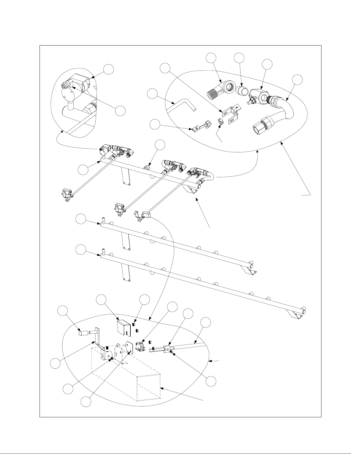
2.13.4 Filter Magic Oil Return Plumbing Components (Including Pump & Motors)
8
large for clarity.
Configurations
Item shown disproportionately
23
8
Typical Full Vat
8
9
5
9
8
19
NOTE: If the filter is to the left
of a dual va t unit, use the 3.5-
inch nip ple (813-0117) i n place
of the 9-inch nipple (Item 9).
18
16
8
8
7
11
6
10
1
4
3
13
12
20
15
Detail of Motor, Pump, and
2
21
17
11
13
10
Vat Configuration
Typical Dual (Split)
Disconnect C omponent s
4
22
PDF compression, OCR, web optimization using a watermarked evaluation copy of CVISION PDFCompressor
2-39
14
Page 40

ITEM PART # COMPONENT
1 Pump Motor
826-1712 100-120 VAC 50/60Hz (with gasket 816-0093)
826-1756 208 VAC 50/60 Hz (with gasket 816-0093)
826-1270 230-250 VAC 50/60 Hz (with gasket 816-0093)
* 807-11973 Pump Service Kit (gasket, shaft seal, and two O-rings)
* 806-6728SP Pump Wiring Assembly (this component is furnished with above motors)
2 826-1264 Pump, 4 GPM (15 LPM) (with gasket 816-0093 and mounting screws)
13 826-1360 Screw, Handle (Pkg. of 25)
14 810-0180 Handle, Plated Diecast Metal (for use on bases built before August 1997)
5 813-0368 Nipple, ½-inch x 16-inch
6 813-0156 Pipe Plug, ½-inch
7 813-0003 Tee, ½-inch
8 810-1057 Flexline, ⅝ -inch x 13-inch Oil Return (two female ends)
9 813-0275 Nipple, ½-inch x 9-inch
10 810-0278 Valve, ½-inch Ball
11 902-0883 Handle, Right Valve
901-0883 Handle, Left Valve
12 813-0165 Elbow, ½-inch x 90º Street
13 813-0022 Nipple, ½-inch Close
14 823-1356 Disconnect Fitting Male
15 826-1392 O-Ring (Pkg. of 5)
16 901-0883 Handle, Left Dual-Vat Valve
17 810-1159 Flexline, 5-inch Oil Return (two female ends)
18 810-1668 Adapter, ⅝ -inch Female to ½-inch Female (used with Item 17)
* 810-1669 Adapter, ⅝ -inch Female to ½-inch Male (used with Item 17)
* 826-1890 Flexline Kit, 7-Inch Oil Return (Items 17, 18, and 810-1669)
19 810-1160 Flexline, 3-inch Oil Return (two female ends)
20 816-0102 Grommet, Oil Diverter
21 900-1472 Diverter, Oil
22 910-1627 Bracket, Male Disconnect Support
23 806-4694SP Contactor Block Assembly
* 813-0117 Nipple, ¾-inch x 3½-inch
* 807-1600 Thermal Switch, 100-120V Baldor Motors
* 807-1601 Thermal Switch, 200-250V Baldor Motors
* 807-1598 Thermal Switch, 100-120V Magnatek Motors
* 807-1599 Thermal Switch, 200-250V Magnatek Motors
* 810-1062 Wiring Harness, Controller to Filter
* 806-7020SP Heater Assembly Strip, 120 VAC 50W, 70-inch
807-1408 Heater Strip Only, 120 VAC 50W, 70-inch
* 806-7021SP Heater Assembly Strip, 250 VAC 90W, 70-inch
807-2348 Heater Strip Only, 250 VAC 90W, 70-inch
* 811-0861 Foam Tape Insulation 3-inch wide (by the foot)
* 811-0746 Tape, Aluminum (2-inch x 50-yard (46m) roll)
* Not illustrated
PDF compression, OCR, web optimization using a watermarked evaluation copy of CVISION PDFCompressor
2-40
Page 41

2.13.5 FootPrint III Filter Motors and Pump Plumbing Components
4
10
2
1
14
5
19
Standard FP III Configuration (Prior to August 1997)
6
5
2
4
1
FPH150 Configurati on
17
18
7
12
13
3
8
9
10
20
11
2
14
15
16
Standard FP III Configuration (August 1997 and Later)
PDF compression, OCR, web optimization using a watermarked evaluation copy of CVISION PDFCompressor
2-41
Page 42

ITEM PART # COMPONENT
1 Motor and Gasket Kits
826-1712 100-120VAC 50/60 Hz (with gasket 816-0093)
826-1756 208 VAC 50/60 Hz (with gasket 816-0093)
826-1270 230-250VAC 50/60 Hz (with gasket 816-0093)
* 807-11973 Pump Service Kit (gasket, shaft seal, and two O-rings)
2 826-1264 Pump, 4GPM (15LPM) (includes gasket 816-0093 and mounting screws)
3 807-2484 Valve, Solenoid Vent (145 ohms)
4 810-1160 Flexline, 3-inch Oil Return (two female ends)
5 813-0062 Elbow, ½-inch x 90º
6 813-0022 Nipple, ½-inch x close
7 810-1404 Flexline, Oil Return (pump to rear manifold)
8 810-1057 Flexline, 13-inch Oil Return (two female ends)
9 810-1373 Flexline, Pump Bypass
10 813-0165 Elbow, ½-inch x 90º Street
11 813-0265 Nipple, ½-inch x 2½-inch
12 813-0537 Nipple, ¼-inch x 2-inch
13 813-0543 Elbow, ¼-inch x 90º Street
14 813-0460 Nipple, ½-inch x 3-inch
15 813-0331 Elbow, ½-inch 3-way
16 813-0304 Bushing, ½-inch to ¼-inch Reducer
17 810-1159 Flexline, 5-inch Oil Return (two female ends)
18 Hose, Heated Oil Return
810-0945 120VAC
810-1037 202-250VAC
19 900-1958 Support, Oil Return
20 813-0530 Tee, ½-inch x ¼-inch x ½-inch NPT Reducing
* 806-9245SP Pump Heater Strip Assembly, 120VAC, 25W, 36-inch
* 807-1420 Pump Heater Strip, 120VAC, 25W, 36-inch
* 806-8004SP Pump Heater Strip Assembly, 120VAC, 40W, 56-inch
807-1472 Pump Heater Strip, 120VAC, 40W, 56-inch
* 806-7755SP Pump Heater Strip Assembly, 120VAC, 100W, 72-inch
* 807-2304 Pump Heater Strip, 120VAC, 100W, 72-inch
* 807-1408 Pump Heater Strip, 120VAC, 50W, 70-inch
* 826-1668 Heat Tape Kit, 120VAC 20w
* 826-1669 Heat Tape Kit, 208-250VAC 20w
* 816-0093 Gasket, Pump Motor
* 807-1600 Thermal Switch, 100-120V Baldor Motors
* 807-1601 Thermal Switch, 200-250V Baldor Motors
* 807-1598 Thermal Switch, 100-120V Magnatek Motors
* 807-1599 Thermal Switch, 200-250V Magnatek Motors
* 806-6728SP Pump Wiring Assembly, FPH150
* 810-1062 Wiring Harness, Controller to Filter
* 811-0861 Foam Tape Insulation 3-inch wide (by the foot)
* 811-0746 Tape, Aluminum (2-inch x 50-yard (46m) roll)
* Not illustrated
PDF compression, OCR, web optimization using a watermarked evaluation copy of CVISION PDFCompressor
2-42
Page 43

2.13.6 FootPrint III with Power Shower Oil Return Plumbing Components
10
Vat on Left
7
FPH350 with Dual
17
NOTE: The assemblies in this illustration represent only
two of the many different configurations used. However,
the individu al componen ts shown are us ed to create all
the other configurations.
10
8
FPH250
7
5
16
8
5
9
6
CONFIGURATIONS
TYPICAL FOOTPRINT III
OIL RETURN PLUMBING
NOTE: Fryers manufactured between August 1997 and
April 1998 had a one-piece welded oil return manifold.
These man ifolds hav e been disc ontinued and are no
longer available. The fittings and flexlines shown in this
illustration must be used to replace failed manifolds.
6
9
7
11
15
2
14
13
1
PDF compression, OCR, web optimization using a watermarked evaluation copy of CVISION PDFCompressor
12
4
3
2-43
7
11
4
15
2
18
19
20
3
1
Page 44

ITEM PART # COMPONENT
1 807-2484 Valve, Solenoid Vent
2 810-0278 Valve, ½-inch NPT Ball
3 810-1372 Fitting, ¼-inch NPT x 90º
4 810-1069 Flexline, Oil Return, 29.5-inch
5 810-1668 Adapter, ½-inch NPT Male (converts female to male)
6 810-1680 Flexline, Oil Return, 6.5-inch
7 813-0003 Tee, ½-inch NPT
8 813-0022 Nipple, ½-inch NPT x Close
9 813-0087 Nipple, ½-inch NPT x 1.5-inch
10 813-0156 Plug, ½-inch NPT
11 813-0247 Nipple, ½-inch NPT x 3.5-inch
12 813-0251 Nipple, ½-inch NPT x 4.5-inch
13 813-0537 Nipple, ¼-inch NPT x 2-inch
14 813-0555 Reducer, ½-inch to ¼-inch NPT
15 902-0883 Handle, Oil Return Valve (Right)
901-0883 Handle, Oil Return Valve (Left)
16 810-1057 Flexline, Oil Return, 13.0-inch
17 806-9437SP Flexline Assembly, Oil Return, 15.5-inch (2 of Item 5 plus Item 16)
18 810-1160 Flexline, Oil Return, 3.0-inch
19 813-0304 Reducer Bushing, ½-inch to ¼-inch NPT
20 813-0016 Nipple, ¼-inch NPT x Close
* 826-1720 Vent Tube, Teflon, ⅜-inch O.D. x 24-inches
* 811-0932 Vent Tube, Teflon, ⅜-inch O.D. per foot
* 816-0224 Insulation, Rubber 3-inch x 6-inch
NOTE: The following Oil Return Flexlines and miscellaneous components may also be used in some
specially configured units. When ordering a flexline, it is recommended that the line be measured (from
outside of flare fitting to outside of flare fitting) to ensure the correct item is ordered.
* 810-1160 Flexline, Oil Return, 3.0-inch
* 810-1339 Flexline, Oil Return, 4.5-inch
* 810-1159 Flexline, Oil Return, 5.0-inch
* 810-1067 Flexline, Oil Return, 8.5-inch
* 810-1043 Flexline, Oil Return, 9.5-inch
* 810-1055 Flexline, Oil Return, 11.5-inch
* 810-1369 Flexline, Oil Return, 17.5-inch
* 810-1068 Flexline, Oil Return, 21.5-inch
* 810-1069 Flexline, Oil Return, 29.5 inch
* 810-1056 Flexline, Oil Return, 52.5-inch
* 810-1669 Adapter, ½-inch NPT Female (converts male to female)
* 901-0883 Handle, Oil Return Valve (Left) (mirror of Item 15 above)
* 902-0883 Handle, Oil Return Valve (Right)
* Not illustrated
PDF compression, OCR, web optimization using a watermarked evaluation copy of CVISION PDFCompressor
2-44
Page 45

2.13.7 FootPrint III with Rear Flush Oil Return Plumbing Components, Standard
Hanger shown
cut away to
reveal elbow.
13
1
2
3
14
12
11
15
10
9
8
7
6 17
5
4
16
FPH350-2L Rear Flush (Typical)
See Page 2-47 for KFCH50 Rear Flush Oil Return Components.
See Page 2-48 for Oil Return Handle Components.
5
PDF compression, OCR, web optimization using a watermarked evaluation copy of CVISION PDFCompressor
2-45
Page 46

ITEM PART # COMPONENT
1 813-0165 Elbow, ½-inch x 90º Street
2 813-0265 Nipple, ½-inch x 2½-inch
3 813-0342 Elbow, ½-inch x 45º Street
4 813-0087 Nipple, ½-inch x 1½-inch
5 810-0278 Valve, ½-inch Ball
* 810-1003 Valve, ½-inch 180º 3-way Ball
6 810-1067 Flexline, 8.5-inch Oil Return
7 813-0062 Elbow, ½-inch x 90º
8 900-2783 Hanger, Rear Flush
9 809-0417 Nut, ¼-20 Serrated Flange
10 813-0320 Nipple, ½-inch x 2-inch
11 813-0003 Tee, ½-inch
12 813-0298 Nipple, ½-inch x 2-inch
13 813-0360 Nipple, ½-inch x 14-inch
14 810-1209 Shaft, Rear Flush Valve
15 809-0601 Clip, Rod End Clevis
16 901-2772 Handle, Left Rear Flush Valve
* 902-2722 Handle, Right Rear Flush Valve
17 810-1668 Adapter, ½-inch NPT Male (converts female to male)
* 810-1056 Flexline, 56-inch Oil Return
* Strip, Heater
806-8065SP 100VAC, 18-inch (46cm), 25 Watt
806-6730SP 100VAC, 56-inch (142cm), 40 Watt
806-5933SP 120VAC, 18-inch (46cm), 25 Watt
806-8004SP 120VAC, 56-inch (142cm), 40 Watt
806-5934SP 200-250VAC, 18-inch (46cm), 25 Watt
806-5932SP 200-250VAC, 36-inch (91 cm), 45 Watt
806-6732SP 200-250VAC, 56-inch (142cm), 70 Watt
* 811-0861 Foam Tape Insulation 3-inch wide (by the foot)
* 811-0746 Tape, Aluminum (50-yard (46m) roll)
* Not illustrated
PDF compression, OCR, web optimization using a watermarked evaluation copy of CVISION PDFCompressor
2-46
Page 47
2.13.8 FootPrint III with Rear Flush Oil Return Plumbing Components, KFC
6 7
1
2
5
4
3
8
9
10
11
with Item 8)
Right Oil Return Valve Assembly
(All components except for Items 4 and 5
are the same for Left Oil Retu rn Val ve
Assembly)
Nut (furni shed
12
TYPICAL CONFIGURATION
(KFCH250 Full Va t Left / Dual Va t Rig ht
shown)
13
14
21
15
16
17
4
Right Handle and Switch Assembly
(All components except for Items 4 and 14
20
are the same for Left Ha ndle an d Swit ch
Assembly)
18
18
19
PDF compression, OCR, web optimization using a watermarked evaluation copy of CVISION PDFCompressor
2-47
See Page 2-28 for Square
Drain components
Page 48

ITEM PART # COMPONENT
1 807-2484 Valve, Solenoid Vent
2 810-1372 Elbow, 90º x ¼-inch NPT x ⅜-inch Tube
* 811-0932 Vent Tube, Teflon, ⅜-inch O.D. per foot
3 809-0601 Clip, Rod End Clevis
4 Shaft, Rear Flush Valve
810-1767
810-1766
For use in left oil return valve assemblies (see illustration below).
For use in right oil return valve assemblies (see illustration below).
5 Handle, Rear Flush Valve
901-2772
902-2772
For use in left oil return valve assemblies.
For use in right oil return valve assemblies.
6 813-0165 Elbow, 90º x ½-inch Street
7 813-0022 Nipple, ½-inch Close
8 810-0278 Valve, ½-inch Ball
* 900-2935 Nut, Oil Return Valve Retainer
* 810-1003 Valve, ½-inch 180º 3-way Ball
9 806-9828SP Flexline Assembly, 9-inch Oil Return
10 813-0469 Cap, ½-inch Pipe
11 810-1360 Manifold, KFCH250 Rear Flush Oil Return
12 810-1357 Manifold, KFCH350 Rear Flush Oil Return
13 810-1378 Manifold, KFCH450 Rear Flush Oil Return
14 Cover, FPH50 Rear Flush Oil Return Microswitch
901-2214
902-2214
For use in left handle and switch assemblies.
For use in right handle and switch assemblies.
15 826-1366 Nut, 4-40 Keps Hex (Pkg. of 25)
16 807-2103 Microswitch
17 810-1186 Cam, Filter System Microswitch
18 826-1377 Setscrew, 10-32 x ¼-inch (Pkg. of 25)
19 816-0220 Insulation, Microswitch
20 Handle, Rear Flush
823-2295 For use in Non-CE applications (see illustration below).
823-2259 For use in CE applications only (see illustration below).
21 812-1253SP Cover, Rear Flush Handle
NOTE: Left and right refer to the fryer as viewed from the front when facing the fryer.
Shaft 810-1767
(Note orientation of flat
and 45° angle to le ft.)
Full Vat or
Left Side of Dual Vat
(Note orientation of slot)
This handle is used in
Handle 823-2259
(Note orientation of slot)
This handle is used in
CE applications.
PDF compression, OCR, web optimization using a watermarked evaluation copy of CVISION PDFCompressor
2-48
Valve OPEN/Filter ON position.
Shaft 810-1766
(Note orientation of flat
and 45° angle to righ t.)
Right Side of Dual Vat
Handle 823-2295
non-CE applications.
NOTE: Handles are shown in
Page 49

2.13.9 FPH150-2 Oil Return Plumbing
19
12
19
17
15
18
13
10
8
7
6
5
3
16
14
11
9
4
2
22
Control Panel Assembly 806-6358SP
shown for reference. Assembly
includes Items 20-21.
PDF compression, OCR, web optimization using a watermarked evaluation copy of CVISION PDFCompressor
2-49
1
21
20
Page 50

ITEM PART # COMPONENT
806-6309SP FPH150-2 Oil Return Plumbing Assembly (Items 1-19)
1 826-1376 Nut, 10-32 Keps (Pkg. of 10)
2 900-2110 Cover, Switch
3 809-0056 Locknut, 5/16-inch x 24 Nylon
4 910-2311 Switch, Actuator
5 809-0519 Washer, 5/16 Spring (2 each)
6 826-1359 Screw, 4-40 x ¾-inch (Pkg. of 10)
7 807-2104 Microswitch, Roller-activated
8 812-0442 Insulation, Microswitch
9 900-2268 Mount, Microswitch
10 826-1366 Nut, 4-40 Keps (Pkg. of 25)
11 806-8342 Bracket, Oil Return Valve
12 810-1055 Flexline, Oil Return, 11.5-inch
13 810-1003 Valve, ½-inch NPT 3-way Ball
14 813-0022 Nipple, ½-inch NPT x Close
15 813-0062 Elbow, ½-inch x 90º
16 813-0165 Elbow, Street, ½-inch x 90º
17 810-1068 Flexline, Oil Return, 21.5-inch
18 810-1067 Flexline, Oil Return, 8.5-inch
19 810-1668 Adapter, ½-inch NPT Male (converts female to male)
806-6358 FPH150-2 Control Panel Assembly, Complete (including Items 20-22)
20 810-0677 Grip, Oil Return Handle
21 910-2312 Handle (Rod), Oil Return
22 810-1115 U-Joint
PDF compression, OCR, web optimization using a watermarked evaluation copy of CVISION PDFCompressor
2-50
Page 51

2.13.10 Oil Return Handle Assembly, Filter Magic & Standard FootPrint III
11 6
9
13
3
8
2
10
7
12
1
14
4
9
16
13
10
4
15
Detail of Switch
Mounting
Handle and switch assembly is shown in right-hand configuration (806-3470SP). Left-hand
configuration (806-3471SP) is mirror image of 806-3470SP using same components. Oil
return valve rod (Item 16) IS NOT a component of either assembly.
ITEM PART # COMPONENT
806-3470SP Handle and Switch Assembly, Right (Items 1-15)
806-3471SP Handle and Switch Assembly, Left (Items 1-15)
1 200-0821 Bracket, Handle and Microswitch
2 807-2103 Microswitch
3 809-0056 Nut, 5/16 – 24, Hex Head, Nylon Lock
4 809-0103 Screw, 8-32 x ½” Slotted Truss Head
5 809-0142 Screw, 5/16 – 24 x ¾” Hex Head
6 809-0200 Washer, Flat
7 826-1381 Washer, Nylatron (Pkg of 10)
8 826-1366 Nut, 4-40 Hex Keps (Pkg of 25)
9 809-0247 Nut, 8-32 Hex Keps
10 826-1359 Screw, 4-40 x ¾” Slot Head (Pkg of 25)
11 810-0220 Spacer, Tubular, .493 OD
12 810-0285 Swivel Fitting, Oil Return Valve Linkage
13 810-1999 Bracket, Valve Handle
14 920-0831 Handle, Oil Return
15 814-0047 Sleeve, Handle
16 910-0832 Rod, Oil Return Valve (must be ordered separately from assemblies)
* 810-0278 Valve, Ball ½-inch
* 826-1878 Kit, Brace Filter
* Not illustrated
PDF compression, OCR, web optimization using a watermarked evaluation copy of CVISION PDFCompressor
2-51
Page 52

2.13.11 Power Shower Assemblies (All Models)
1
2
3
4
ITEM PART # COMPONENT
806-4442SP
806-4476SP
Power Shower Assembly, Full Vat, Complete
Power Shower Assembly, Dual Vat, Complete
1 814-0001 Grip, Handle
2 809-0415 Screw, Cleanout
3 826-1390 Seal (Gasket) (pkg of 5)
4 826-1344 O-Ring (pkg of 5)
PDF compression, OCR, web optimization using a watermarked evaluation copy of CVISION PDFCompressor
2-52
Page 53

2.13.12 Oil Disposal Systems Plumbing
14
13
8
11
12
10
9
These components
are part of Item 13.
32
Detail of Item 1
31
23a
28
2
22
21
27
34
33
19
1
20
17
806-9330SP
25
6
806-9109SP
5
30
16
15
19
23b
1
17
1
20
806-9087SP
17
18
17
23a
2
26
3
4
22
7
21
4
2
29
30
810-0490
PDF compression, OCR, web optimization using a watermarked evaluation copy of CVISION PDFCompressor
2-53
Page 54

ITEM PART # COMPONENT
806-9087SP Oil Disposal Plumbing Assembly (side discharge configuration)
806-9330SP Oil Disposal Plumbing Assembly (rear discharge configuration) H50 oil Return
1 806-8762SP Ball Valve with Microswitch Assembly
*
2 810-0487 Quick Disconnect, ½-inch Male
3 809-0454 Nut, ½-inch Conduit (mounts between Item 2 and Item 6)
4 826-1374 Screw, #10 x ½-inch Hex Head (Pkg of 25)
5 910-8809 Bracket, Oil Disposal Mounting (rear connection configuration)
6 809-0951 Clamp, Hose (limits movement of plumbing through mounting bracket)
7 910-8085 Bracket, Oil Disposal Mounting (side connection configuration)
8 814-0047 Sleeve, Valve Handle
9 900-5953 Handle, Oil Disposal Valve
10 809-0237 Nut, 4-40 Hex Head Keps
11 807-2103 Microswitch, Roller Activated
12 900-8057 Bracket, Microswitch Mounting
13 810-0278 Valve, ½-inch Gemini (without handle)
* 900-2935 Nut, Oil Return Valve Retainer
14 809-0354 Screw, 4-40 x ¾-inch Round Head
15 810-1680 Flexline, 6.5-inch Oil Return
16 810-1668 Adapter, ½-inch NPT Male (converts female to male)
17 813-0003 Tee, ½-inch x ½-inch x ½-inch
18 813-0251 Nipple, ½-inch x 5-inch
19 813-0320 Nipple, ½-inch x 8-inch
20 813-0275 Nipple, ½-inch x 9-inch
21 813-0062 Elbow, ½-inch x 90º
22 813-0022 Nipple, ½-inch x Close
23a 813-0156 Plug, ½-inch Pipe Hex Head
23b 813-0463 Plug, ½-inch Pipe Counter Sink
24 813-0087 Nipple, ½-inch x 1½-inch
25 813-0541 Nipple, ½-inch x 25½-inch
26 813-0265 Nipple, ½-inch x 2½-inch
27 813-0298 Nipple, ½-inch x 2-inch
28** 806-9178SP Hose Assembly, Oil Disposal (Items 29-32) Sonic
29 810-0490 Quick Disconnect Fitting, ½-inch Female
30 813-0165 Elbow, ½-inch x ½-inch 90º Street
31 810-1434 Hose Assembly, 66-inch Oil
32 810-0667 Check Valve, ½-inch
33 813-0037 Coupling, ½ NPT x 1-⅛
34 813-0360 Nipple, ½ x 14.00-inch NPT BM Pipe
* KIT3578SP Kit, Oil Return FPH50 (Sonic)
* 806-9109SP Kit, Oil Return FM
* WIR0315SP Wire Assembly Sonic Oil Disposal
** Not illustrated.
** Item 28 is NOT a component of either 806-9087SP or 806-9330SP.
WIR0315SP Wire Assembly, Ball Valve Microswitch
PDF compression, OCR, web optimization using a watermarked evaluation copy of CVISION PDFCompressor
2-54
Page 55

2.13.13 Assembly Wand Plumbing Japan
1
12
2
7
15
3
14
10
11
5
ITEM PART # COMPONENT
806-9700SP Plumbing Assembly, Japan Wand
1 807-2103 Switch, CE Micro
2 826-1366 Nut, 4-40 (Pkg. of 25)
3 826-1359 Screw, 4-40 x ¾ (Pkg. of 25)
4 810-0278 Valve, ½-inch Ball
5 810-0487 Coupling, Male
6 813-0003 Tee, ½ x ½ x ½
7 813-0002 Nipple, ½ x Close NPT
8 813-0156 Plug, ½ NPT
9 813-0247 Nipple, ½ x 3½-inch NPT
10 813-0298 Nipple, ½ x 2-inch NPT
11 814-0047 Sleeve, Handle Valve Red w/ Logo
12 816-0220 Insulation, RF Switch
13 823-2029 Support, Oil Return
14 900-1862 Bracket, Microswitch Mounting ½ Ball Valve
15 900-2839 Handle, Valve Wand Japan
16 900-2849 Cover, Wand Microswitch Japan
16
4
9
13
6
8
PDF compression, OCR, web optimization using a watermarked evaluation copy of CVISION PDFCompressor
2-55
Page 56

2.13.14 Oil Disposal Wand Assembly
2
1
ITEM PART # COMPONENT
806-7459 Assembly, Oil Disposal Wand
1 810-0603 Wand, FB Filter
2 810-1471 Hose, 24 FPH50 Japan
3 810-0490 Quick Disconnect, ¼-inch Female
3
2.14 Frypot Assemblies and Component Parts
2.14.1 Replacement Frypots and Frypot Insulation Kits
ITEM PART # COMPONENT
Replacement Frypot Assemblies, Complete
106-1026 Full Vat, Non-Filter, Natural Gas
106-1049SP Full Vat, Power Shower & Rear Flush, Natural Gas
106-1050SP Full Vat, Power Shower & Rear Flush, Propane Gas
106-1047SP Full Vat, Power Shower, w/Four Holes, Natural Gas* Replaced by 106-1049SP
106-1048SP Full Vat, Power Shower, w/Four Holes, Propane Gas*Replaced by 106-1050SP
106-1043SP Full Vat, Power Shower, Manufactured Gas
106-1058 Dual Vat, Power Shower, Natural Gas
106-1079SP Dual Vat, Power Shower & Rear Flush, Natural Gas
106-1080SP Dual Vat, Power Shower & Rear Flush, Propane Gas
106-1066SP Dual Vat, Power Shower, Manufactured Gas
106-1070SP Dual Vat, Rear Flush (KFC, Natural Gas)
106-1071SP Dual Vat, Rear Flush (KFC, Propane Gas)
Replacement Insulation Kits
826-0929 Full Vat, Complete
826-0931 Full Vat, Burner Only
826-0930 Dual Vat, Complete
826-0932 Dual Vat, Burner Only
826-1881SP Hardware Kit, FV Frypot
826-1882 Hardware Kit, DV Frypot
106-1019SP Flue Assembly, FV
106-1018SP Flue Assembly, DV
823-3315 Retainer W/A, Inner Left Front FV
823-3316 Retainer W/A, Inner Right Front FV
* Used only on fryers with non-Frymaster remote computers. (Jack In the Box and Foodmaker)
NOTE: See pages 2-58 and 2-60 for replacement burners and replacement burner rails.
PDF compression, OCR, web optimization using a watermarked evaluation copy of CVISION PDFCompressor
2-56
Page 57

2.14.2 Full Vat Frypot Assembly, Component Parts
39
11
23
37
6
18
4
4012
9
3
43
31
21
30
23
39
32
16
1 20 34 19
24 17
35
15
See Page 2-58 for
19
3315
2
26
5
22
8
27
38
NOTE: All insulation and gask ets
can be ordered in a single kit, P/N
826-0929.
Kit 826-0931 contains the insulation
and gaskets required when replacing
burners (Items 16, 18, 20, and 25).
PDF compression, OCR, web optimization using a watermarked evaluation copy of CVISION PDFCompressor
2-57
14
41
10
13
27
11 29
25 36 8
28
10
7
Full Vat Frypot Assembly (Typical)
Page 58

ITEM PART # COMPONENT
Full Vat Frypot Assembly, Complete (see Page 2-58 for P/Ns)
1 823-3316
2 823-3315
Retainer, Lower Front Insulation, Right (before 09/01 use 200-0934)
Retainer, Lower Front Insulation, Left (before 09/01 use 200-0935)
3 200-0936 Back, Combustion Chamber, Left
4 200-0937 Back, Combustion Chamber, Right
5 200-2227 Retainer, Upper Front Insulation
6 106-1019SP
Flue Assembly, Full Vat (before 09/01 use 806-5859SP)
7 826-1372 Nut, ¼-20 Hex Head Grip (Pkg of 10)
8 826-1371 Screw, #8 x ½-inch Hex Head Drill Point (Pkg of 25)
9 809-0362 Screw, # 8 x 1¼-inch Hex Head Drill Point
10 826-1383 Washer, ¾-inch OD x ¼-inch ID Steel (Pkg of 5)
11 809-0804 Nut, ¼-20 Washer-Face Lock
12 810-0406
13 826-1340
14 810-0500
15 826-1072
Spacer, ¼-inch x 1½
Spacer, ¼-inch x 1
Spacer, ¼-inch x
inch Long
-
3
/
-inch Long (Pkg of 10)
16
15
/16-inch Long
Burner, Natural or Propane, Universal (use 826-1073 for Mfg gas)
16 812-0355 Insulation, Lower Rear
17 812-0356 Insulation, Sight Glass Gasket
18 816-0577 Insulation, Burner (½-inch x 36-inches)
19 812-0404 Insulation, Front Seal (for left and right)
20 812-0457 Insulation, Lower Front
21 812-0706 Insulation, Upper Burner Rail
22 812-0993 Insulation, Upper Oil Zone
23 812-1029 Insulation, Combustion Chamber Side
24 814-0048SP Sight Glass
25 816-0057 Gasket, Plenum Chamber
26 816-0560 Insulation, Upper Front
27 816-0561 Insulation, Combustion Chamber, Outer
28 823-0969
29 823-3304
Plenum, Full Vat (for CE units, use 823-1048)
Combustion Chamber Outer Front, Right (before 09/01 use 823-1169SP)
30 823-1777 Burner Rail, Left
31 Frypot, Full Vat (shown for assembly reference only)
32 823-3142 Burner Rail, Right
33 824-0863 Retainer, Left Front Seal Insulation
34 824-0864 Retainer, Right Front Seal Insulation
35 900-1031 Retainer, Sight Glass, ¾-inch
36 900-1049 Retainer, Plenum Chamber Gasket
37 900-1221 Retainer, Rear Insulation and Combustion Chamber Back
38 900-1515 Brace, Upper Oil Zone Insulation
39 900-4452 Retainer, Combustion Chamber Side Insulation
40 930-0818 Bracket, Flue to Frypot Connection
41 823-3305
Combustion Chamber Outer Front, Left (before 09/01 use 823-11691SP)
42 809-0500 Screw, #10 x ½-inch Hex Washer Head
43 900-4253 Strip, Fluecap Retainer
* 813-0156 Plug, ½-inch NPT BM (for blocking unneeded ports)
* 813-0336 Plug, ½-inch SS (for blocking unneeded ports)
* 910-2474 Pot-to-Pot Gap Clip
* 900-0857 Brace, Frypot to Cabinet
*Not illustrated.
PDF compression, OCR, web optimization using a watermarked evaluation copy of CVISION PDFCompressor
2-58
Page 59

2.14.3 Dual Vat Frypot Assembly, Component Parts
8
1
18
39
40
41
29
19
27
38
2
34
21
13
28
19
16
33
9 32
15
12
17
30
NOTE: All insula tion and gas kets
can be ordered in a single kit, P/N
826-0930.
Kit 826-0932 contains the insulation
and gaskets required when replacing
21
38
14
22
See Page 2-58 for P/N’s
Dual Vat Frypot Assembly (Typical)
10
6
25
3
20
37
5
11
8
burners (Items 13, 15, 17, and 23).
24 35
5 31
36
23
26
4 7
PDF compression, OCR, web optimization using a watermarked evaluation copy of CVISION PDFCompressor
2-59
Page 60

ITEM PART # COMPONENT
Dual Vat Frypot Assembly, Complete (see Page 2-58 for P/Ns)
1 106-1018SP
Flue Assembly, Dual Vat (before 09/01 use 806-5860SP)
2 200-0941 Back, Combustion Chamber
3 200-2229 Retainer, Upper Front Insulation
4 826-1372 Nut, ¼-20 Hex Head Grip (Pkg of 10)
5 809-0360
Screw, #8 x ⅜-inch Slotted Hex Washer Head
6 809-0362 Screw, # 8 x 1¼-inch Hex Head Drill Point
7 826-1383 Washer, ¾-inch OD x ¼-inch ID Steel (Pkg of 5)
8 809-0500 Screw, #10 x ½-inch Hex Washer Head
9 809-0804 Nut, ¼-20 Washer-Face Lock
10 826-1340
11 810-0500
12 826-1072
Spacer, ¼-inch x 1
Spacer, ¼-inch x
Burner, Natural or Propane, Universal (use 826-1073 for Mfg gas)
3
/
-inch Long (Pkg. of 10)
16
15
/16-inch Long
13 812-0354 Insulation, Lower Rear
14 812-0356 Insulation, Sight Glass Gasket
15 816-0577 Insulation, Burner (½-inch x 36-inches)
16 812-0404 Insulation, Front Seal (for left and right)
17 812-0458 Insulation, Lower Front
18 812-0688 Insulation, Flue Collector
19 812-0706 Insulation, Upper Burner Rail
20 812-0993 Insulation, Upper Oil Zone
21 812-1029 Insulation, Combustion Chamber Side
22 814-0048SP Sight Glass
23 816-0057 Gasket, Plenum Chamber
24 816-0558 Insulation, Combustion Chamber, Outer
25 816-0559 Insulation, Upper Front
26 823-0970SP
Plenum, Dual Vat (use 823-1049 for CE units)(823-2181 for H150-2’s)
27 823-2822 Burner Rail, Left
28 823-2823 Burner Rail, Right
29 Frypot, Dual Vat (shown for assembly reference only)
30 823-3302
31 823-3303
Retainer, Lower Front Insulation (before 09/01 use 823-0983SP)
Combustion Chamber Outer Front (before 09/01 use 823-0968SP)
32 824-0865 Retainer, Left Front Seal Insulation
33 824-0866 Retainer, Right Front Seal Insulation
34 900-0914 Retainer, Rear Insulation and Combustion Chamber Back
35 900-1031 Retainer, Sight Glass, ¾-inch
36 900-1049 Retainer, Plenum Chamber Gasket
37 900-1515 Brace, Upper Oil Zone Insulation
38 900-4452 Retainer, Combustion Chamber Side Insulation
39 930-0818 Bracket, Flue to Frypot Connection
40 900-4253 Strip, Fluecap Retainer
41 824-0541 Riser, DV Pot Divider W/A
* 910-2474 Pot-to-Pot Gap Clip
* 813-0156 Plug, ½-inch NPT BM (for blocking unneeded ports)
* 813-0336 Plug, ½-inch SS (for blocking unneeded ports)
* 900-0857 Brace, Frypot to Cabinet
*Not illustrated.
PDF compression, OCR, web optimization using a watermarked evaluation copy of CVISION PDFCompressor
2-60
Page 61
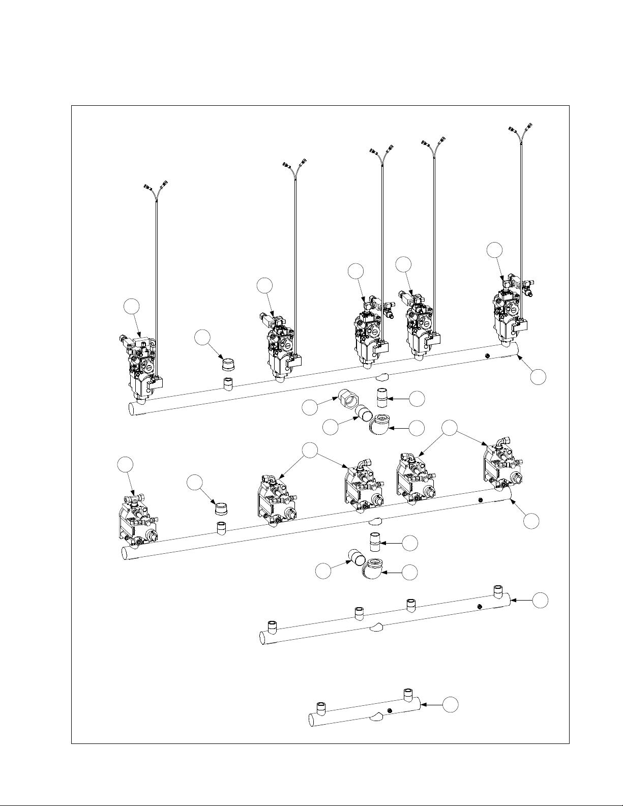
2.15 Gas Supply System Assemblies and Component Parts
2.15.1 FM/MJH50 Gas Manifold Assemblies
13
12
11
4
13
12
3
8
CE FM/MJH350-4R (Typical)
9
4
NON-CE FM/MJH350-4R (Typical)
7
10
7
5
6
5
6
10
3
2
See Page 2-63 for details of gas valve assemblies.
1
PDF compression, OCR, web optimization using a watermarked evaluation copy of CVISION PDFCompressor
2-61
Page 62

ITEM PART # COMPONENT
1 810-0959 FM/MJH150 Gas Manifold
2 810-0661 FM/MJH250 Gas Manifold
3 810-0660 FM/MJH350 Gas Manifold
4 813-0469 Cap, Pipe, ½-inch, BM
5 813-0111 Nipple, ¾-inch x 1¾-inch, BM
6 813-0305 Elbow, 1-inch x ¾-inch, BM
7 813-0138 Nipple, 1-inch x Close, BM
8 813-0505 Adapter, 1-inch NPT x 1-inch BSPT
9 Gas Valve Assembly, Non-CE Full Vat
806-5304SP Natural Gas
806-5305SP Propane Gas
10 Gas Valve Assembly, Non-CE Dual Vat
806-5306SP Natural Gas
806-5307SP Propane Gas
11 Gas Valve Assembly, CE Full Vat
806-7467SP Natural (G20, G25) Gas
806-7466SP Propane (G30, G31) Gas
12 Gas Valve Assembly, CE Dual Vat (Left)
806-7465SP Natural (G20, G25) Gas
806-7464SP Propane (G30, G31) Gas
13 Gas Valve Assembly, CE Dual Vat (Right)
806-7463SP Natural (G20, G25) Gas
806-7462SP Propane (G30, G31) Gas
* 810-1306 Gas Valve, Manual ½”
* 810-1307 Gas Valve, Manual ¾”
NOTE: Batteries larger than FM/MJH350 use combinations of the above components (e.g., a FM/MJH450
uses one of Item 1 and one of Item 3 plus the appropriate gas valves and connection fittings for the specific
configuration).
PDF compression, OCR, web optimization using a watermarked evaluation copy of CVISION PDFCompressor
2-62
Page 63

2.15.2 Gas Valves, Gas Lines and Fittings
2
1
7
8
9
10
3
6
4
5
11
12
13
14
15
27
26
16
22
27
17
18
23
30
19
24
29
20
21
27
25
28
30
27
PDF compression, OCR, web optimization using a watermarked evaluation copy of CVISION PDFCompressor
2-63
Page 64

ITEM PART # COMPONENT
1 Gas Valve and Bushing, Non-CE
826-1122 Natural (G20, G25) Gas
826-1123 Propane (G30, G31) Gas
826-1576 Gas Valve and Harness CE
2 810-0691 Vent Tube (used with Item 1) (for CE units, use 810-1166)
3 810-1715 Gas Valve, Universal CE (G20/G25/G30/G31) adjustable 2” to 20”
4 810-1041 Accessory Kit (2 straight and 2 elbow flanges, screws, O-rings, LP gas spring)
5 806-9678SP Plug Assembly, CE Gas Valve (used with Item 3)
6 807-1229 Gas Valve, Manufactured Gas
7 810-1176 Tap, ⅛-inch NPT Pressure
8 813-0411 Plug, ⅛-inch NPT Allen-head Pipe
9 813-0304 Bushing, ½-inch to ¼-inch NPT Reducer
10 810-1006 Bushing, ¼-inch to ⅛-inch NPT Reducer
11 813-0004 Elbow, 90º x ⅛-inch NPT
12 813-0354 Elbow, 90º x ⅛-inch NPT x ⅛-inch Tube (Brass)
13 813-0302 Elbow, 90º x ⅜-inch Tube x ¼-inch Male NPT (Brass)
14 813-0502 Elbow, 90º Street x ¼-inch (Brass)
15 813-0340 Connector, ⅛-inch Tube to ⅛-inch Male NPT (Brass)
* 810-0502 Connector, ⅛-inch Tube to ⅛-inch Male NPT (Brass) (with Item 6 only)
16 810-1025 Connector, ⅜-inch Tube to ¼-inch Male NPT (Brass)
17 813-0507 Coupling, ¼-inch NPT (Brass)
18 813-0378 Cross Fitting, ½-inch Female NPT (Brass)
19 810-1026 Tee, ¼-inch NPT Street (Brass)
20 813-0495 Tee, ¼-inch Male NPT Branch (Brass)
21 813-0377 Tee, ⅛-inch Female NPT (Brass)
22 813-0016 Nipple, ⅛-inch NPT Close
23 813-0315 Nipple, ⅛-inch NPT x 1½-inch
24 813-0405 Nipple, ⅛-inch NPT x 2-inch
25 813-0471 Nipple, ¼-inch NPT x 1½-inch
26 900-3693 Gas Tube (Left), H50 FV Manufactured Gas (pre-formed)
27 810-0503 Compression Nut (Ferrule), ½-inch Manufactured Gas Tube
28 900-3692 Gas Tube (Right), H50 FV Manufactured Gas (pre-formed)
* 900-3691 Gas Tube (Left and Right), H50 DV Manufactured Gas (pre-formed)
29 Flexible Stainless Steel Gas Line (Flexline), ⅜-inch OD
810-1353 9-inch (22.9 cm) (826-1530 Kit includes 2 of Item 30)
810-1354 12-inch (30.5 cm)(826-1531 Kit includes 2 of Item 30)
810-1355 15-inch (38.1 cm) (826-1532 Kit includes 2 of Item 30)
30 810-0494 Compression Nut (Ferrule), ⅜-inch Flexible Gas Line
* Enrichment Tube, ⅛-inch OD
811-0752 5½-inch (14 cm)
811-0756 8½-inch (21.6 cm)
811-0800 12½-inch (31.8 cm)
812-0742 18-inch (45.7 cm)
900-7450 20-inch (51 cm)
811-0759 Variable Length (sold by the foot)
* 810-1166 Vent Tube CE (used with Item 3)
* 813-0340 Fitting, Enrichment Tube for Gas Valve End
* 810-0502 Fitting, Enrichment Tube for Ignitor Connection
* Not illustrated.
PDF compression, OCR, web optimization using a watermarked evaluation copy of CVISION PDFCompressor
2-64
Page 65

2.16 Probe, Probe Guard and Thermostat
1
3
2
ITEM PART # COMPONENT
1 826-1177
High Limit Thermostat (425°F/218°C)
2 806-4206 Temperature Probe Assembly
3 210-0681 Probe Guard (replaced 810-0625)
PDF compression, OCR, web optimization using a watermarked evaluation copy of CVISION PDFCompressor
2-65
Page 66

2.18 Relays, Transformers, Wiring Assemblies and Related Parts
2.18.1 Filter Box Components
NOTE: See illustrati ons on Page 2-69
to determine the corre ct plu g assemb ly
and harness required for your specif ic
configuration.
1
2
93
9
13
10
6 8 11 12
4 5 7
9
Complete Assemblies:
806-8581SP 100V w/4-Terminal Relay
806-8358SP 120V w/4-Terminal Relay
14
806-7496SP 120V w/5-Terminal Relay
806-8582SP 208/250 w/4-Terminal Relay
For FM see 806-6209
NOTE: The trans former ( Item 4)
may differ in appea ran ce f rom the
illustration dependi ng upon the
voltage of the filter system.
ITEM PART # COMPONENT
1 Plug Assembly, Top Position
806-6725SP 4-Wires w/o keying plug (see illustration on Page 2-69)
806-8021SP 6-Wires w/keying plug in pin 5 (see illustration on Page 2-69)
2 Plug Assembly, Bottom Position
806-6719SP 5-Wires w/o keying plug in pin 6 (see illustration on Page 2-69)
806-7494SP 5-Wires w/keying plug in pin 6 (see illustration on Page 2-69)
3 807-2434 Relay, 5-Terminal Pump Motor (for 4-Terminal, use 807-0012)
4 Transformer
807-2176 100-120V Primary 12/24V Dual-Tap Secondary 50/60 Hz 50VA
807-0855 120V Primary 12V Secondary 50/60Hz, 20VA
807-0800 120V Primary 24V Secondary 50/60 Hz 50VA
807-1999 202-240V Primary 24V Secondary 50/60 Hz 50VA
5 809-0096
Screw, 6-32 x ⅝
inch Slot Head
-
6 826-1366 Nut, 4-40 Keps Hex (Pkg. of 25)
7 809-0250 Nut, 6-32 Keps Hex
8 826-1359 Screw, 4-40 x ¾-inch Slotted Pan Head (Pkg. of 25)
9 809-0360
Screw, #8 x ⅜-inch Slotted Washer Hex Head
10 810-0044 Plug, ⅝-inch
11 810-1164 Terminal Block
12 816-0217 Paper, Insulating
13 900-5250 Box, FP III Filter
14 900-5530 Cover, FP III Filter Box
* 810-1062 Harness, Filter Box
* Not illustrated
PDF compression, OCR, web optimization using a watermarked evaluation copy of CVISION PDFCompressor
2-66
Page 67

2.18.2 Transformer Box Components
236
43
44
239
FPH150 ( 208-240V )
"Baby FootPrint"
35
34
2210
1 23
FPH150 (100V)
7 23
3 4 18 21
2443
26
8 13 14 17
1 23
236
43
41
31
2210
36
22
42
5 23
3 4 18 21
FPH150 (120V)
8 13 14 17
25
2 12 16
MJ/FMH150 (100-120V)
35
34
18 21 28 30
25
229
25
22
231
239
43
FPH150 ( 208-240V )
41
31
229
36
22
42
211843
30282118
25
12 162
MJ/FMH150 (208-240V)
47
1714138
46
2210
25
2 12 16
22
36
22
36
MJ/FM/FPH250 (100-120V) MJ/FM/FPH250 (208-240V)
37
33
2210
22
36
38
MJ/FM/FPH350 (100-120V)
40
8 13 14 17
25
2 12 16
2 12 16
37
229
22
40
48
45
2 12 16
MJ/FM/FPH250 RF (100-120V)
33
18 21 28 30
25
2 12 16
36
38
MJ/FM/FPH350 (208- 240V)
Note: H450 went to
32
2210
2-Double Boxes
11 13 15 20
25
32
229
18 21 27 29
25
22
39
2 12 16
22
39
2 12 16
MJ/FM/FPH450 (100-120V) MJ/FM/FPH450 (208-240V)
PDF compression, OCR, web optimization using a watermarked evaluation copy of CVISION PDFCompressor
2-67
Page 68

ITEM PART # COMPONENT
1 807-0012 Relay, 18 Amp ⅓-HP 24V Coil
2 807-0070 Terminal Lug, Brundy KPA4C
3 807-0255 Terminal Jumper
4 807-0273 Terminal Block, 16-Pin
5 807-0800 Transformer, 120V Primary 24V Secondary 50/60 Hz 50VA
6 807-0855 Transformer, 120V Primary 12V Secondary 50/60 Hz 20VA
7 807-1238 Transformer, 100V Primary 24V Secondary 50/60 Hz 50VA
8 807-1973 Connector, 4-Post Terminal
9 807-1999 Transformer, 202-240V Primary 24V/12V Secondary 50/60 Hz 50VA Dual Tap
* 807-0979 Transformer, 208/240V Primary 12V Secondary 50/60Hz 20VA
* 806-4000 Transformer Assy. 220/240V Primary 12V Secondary 50/60Hz 40VA
(German & Dutch) requires fuse 807-1597
* 807-2180 Transformer, 208-240V Primary 24V Secondary 50/60Hz 50VA
* 806-4001SP Transformer, 220/240V Primary 24V Secondary 50/60Hz 75 VA (German & Dutch)
Requires fuse 807-1597
10 807-2176 Transformer, 100-120V Primary 12/24V Dual-Tap Secondary 50/60 Hz 50VA
11 807-2608 Terminal Block, 50A 2-Stud/Pole Post
12 809-0050 Nut, 2-32 Hex
13 809-0052 Nut, 10-24 Hex
14 826-1362 Nut, ¼-20 Hex (Pkg. of 10)
15 826-1365 Screw, 6-32 x ⅜-inch Slotted Truss Head (Pkg. of 25)
16 826-1363 Screw, 2-32 x ½-inch Slotted Truss Head (Pkg. of 25)
17 826-1389 Screw, ¼-20 x ¾-inch Hex Head (Pkg. of 10)
18 826-1366 Nut, 4-40 Keps Hex (Pkg. of 25)
19 809-0247 Nut, 2-32 Keps Hex
20 809-0250 Nut, 6-32 Keps Hex
21 826-1359 Screw, 4-40 x ¾-inch Slotted Pan Head (Pkg. of 25)
22 809-0360
23 826-1371 Screw, #8 x ½-inch Hex Head (Pkg. of 25)
24 809-0362 Screw, #8 x 1- Hex Washer Head
25 826-1374 Screw, #10 x ½-inch Hex Washer Head (Pkg. of 25)
26 810-0045 Bushing, .875 Diameter
27 810-1162 Terminal Block, 4 Place
28 810-1163 Terminal Block, 3 Place
29 816-0218 Paper, 4 Place Terminal Block Insulating
30 816-0219 Paper, 3 Place Terminal Block Insulating
31 900-2697 Box, Transformer H150/H152
32 900-2698 Box, Transformer H450/H452
33 900-2699 Box, Transformer H350/H352
34 900-2700 Box, Transformer H250/H252
35 900-2702 Cover, H250/252 Transformer Box Top
36 900-2703 Cover, H50/H52 Transformer Box Front (H150 L, H250 L & R, H350 L)
37 900-2704 Cover, H350/H352 Transformer Box Left Top
38 900-2705 Cover, H350/H352 Transformer Box Right Front
39 900-2706 Cover, H450/H452 Transformer Box Left and Right Front
40 900-2707 Cover, H450/H452 Transformer Box Top
41 900-2708 Cover, H150/H152 Transformer Box Top
42 900-2709 Cover, H150/H152 Transformer Box Right Front
43 900-4555 Bracket, Transformer Mount
44 900-5560 Shield, Component
45 900-5923 Cover, H250/H252 Transformer Box Right Front
46 900-5924 Box, H250/H252 Transformer
47 900-5927 Cover, H250/H252 Transformer Box Top
48 900-5928 Cover, H250/H252 Transformer Box Left Front
* 806-7999SP FPH150 Basket Lift Wiring Assembly
* Not illustrated.
Screw, #8 x ⅜-inch Slotted Hex Washer Head
PDF compression, OCR, web optimization using a watermarked evaluation copy of CVISION PDFCompressor
2-68
Page 69

2.19 Wiring Harnesses, Wiring Assemblies and Plug Assemblies
Filter Box Wiring
1
7
2
3
4
5
6
ITEM PART # COMPONENT
1 806-8021SP 120V U.S. and 100/120V Non-CE Export Upper 9-Pin Plug Assembly
2 806-7494SP 120V U.S. Lower 9-Pin Plug Assembly (Main)
3 806-6725SP 230V CE Upper 9-Pin Plug Assembly
4 806-6719SP 100/120V Non-CE Export and 230V CE Lower 9-Pin Plug Assembly
5 810-1062 Cable, Filter Box Lower 9-Pin Plug to 807-2000/2001 C2 Connector (FP) w/ BL
* 807-2016 Cable, Filter Box Lower 9-Pin Plug to 807-2000/2001 C2 Connector (FM) Main
Wiring Harness
* 807-2000 Cable, 810-1062 C2 Connector to Component Box (units w/Basket Lift)
6 807-2001 Cable, 810-1062 C2 Connector to Component Box (units w/o Basket Lift)
7 Pump Motor to Filter Box Wiring Assembly
806-6728SP FootPrint
806-4347 Filter Magic
* 807-3695 H50 Basket Lift Cable
* 807-0160 12-pin Connector Male FPH150
* WIR0129SP FPH150 Rear Ext. Box
* WIR0233SP 100-250V CE and Non-CE Export Filter Box Internal Wiring Bundle
* WIR0234SP 120V U.S. Filter Box Internal Wiring Bundle
* WIR0355SP FPH150 Rear Ext. Box (Panda Express)
* Not illustrated.
PDF compression, OCR, web optimization using a watermarked evaluation copy of CVISION PDFCompressor
2-69
Page 70

Main Wiring Harnesses
U.S. and Non-CE harness (shown)
has two unterminated wires.
Unterminated wires.
CE harness has two unterminated
wires plus two additional wires with
push-on t erminal s.
ITEM PART # COMPONENT
807-1978 U.S. and Non-CE Export (before 05/95, use 806-2076SP)
806-2077SP U.S. and Non-CE Export (DV before 05/95)
807-2168 CE Main Wiring Harness
806-2071 Interface Harness- Computer to Interface Board
807-2275 Interface Harness- Computer to Interface Board (MFG Gas Only)
807-2657 Ferrite Collar Bead
Power Cords
1
2
3
4
5
ITEM PART # COMPONENT
1 806-5332SP Power Cord, 120V w/Grounding Plug (w/Push-On Terminals and Clamp)
* 806-7742 Power Cord, 120V w/Grounding Plug (w/Ring Terminals, no Clamp)
* 807-0154 Power Cord, 120V w/Grounding Plug (w/o Terminals or Clamp)
2 806-6229SP Power Cord, 240V w/o Plug
3 807-1696 Power Cord, CE
4 807-1685 Power Cable, 110-inch, 3-wire, 16-gauge, 450V, 18A
5 807-1560 Strain Relief
PDF compression, OCR, web optimization using a watermarked evaluation copy of CVISION PDFCompressor
2-70
Page 71

Transformer Box Plug Assemblies
1
5
9
2
6
10
3
7
11
4
8
12
PDF compression, OCR, web optimization using a watermarked evaluation copy of CVISION PDFCompressor
2-71
Page 72

ITEM PART # COMPONENT
1 806-6164SP FMH150, MJ/FM/FPH250-Right, MJ/FM/FPH350/450-Left Front
2 806-6165SP MJ/FM/FPH250-Left, MJ/FM/FPH350/450-Left Rear
3 806-6166SP MJ/FM/FPH350-Right, MJ/FM/FPH450-Right Rear
4 806-6167SP MJ/FM/FPH450-Right Front
5 806-6637 FMH150 CE, MJ/FM/FPH250 CE-Left
6 806-6638 MJ/FM/FPH350 CE-Left Front, MJ/FM/FPH450 CE-Left Rear
7 806-6639 MJ/FM/FPH350 CE-Left Rear, MJ/FM/FPH450 CE-Left Front
8 806-6640 MJ/FM/FPH450 CE-Right Front
9 806-6641 MJ/FM/FPH350 CE-Right, MJ/FM/FPH450 CE-Right Rear
10 806-6642 MJ/FM/FPH250 CE-Right
11 806-8712SP MJ/FM/FPH250-Left
12 806-8713 MJ/FM/FPH250-Right
* Transformer Box Wire Bundle
WIR0110SP MJ/FMH150, MJ/FM/FPH250
WIR0111SP MJ/FM/FPH350
WIR0112 MJ/FM/FPH450
WIR0129SP FPH150
WIR0149 MJ/FM/FPH250 CE
WIR0150 MJ/FM/FPH350 CE
WIR0151 MJ/FM/FPH450 CE
WIR0152 MJ/FMH150 CE
WIR0355SP FPH150 (Panda Express Variant)
WIR0365 FPH150 CE (Baby FootPrint Variant)
* 807-0156 9-Pin Connector Female
* Not illustrated.
1
2
Gas Valve Wiring
ITEM PART # COMPONENT
1 806-3941SP Harness, Full Vat Gas Valve
2 806-3940SP Harness, Dual Vat Gas Valve
3 806-9678SP Plug Assembly, CE Gas Valve
3
PDF compression, OCR, web optimization using a watermarked evaluation copy of CVISION PDFCompressor
2-72
Page 73

2.20 Wiring Connectors and Pin Terminals
1 2
6
11
3
7 9 10
8
12
4
13
5
ITEM PART # COMPONENT
1 807-1068 2-Pin Female
2 807-0158 6-Pin Female
3 807-0156 9-Pin Female
5 807-0159 12-Pin Female
5 807-0875 15-Pin Female
6 807-1067 2-Pin Male
7 807-0157 6-Pin Male
8 807-0155 9-Pin Male
9 807-0160 12-Pin Male
10 807-0804 15-Pin Male
11 826-1341 Terminal, Female Split Pin (Pkg of 25)
12 826-1342 Terminal, Male Split Pin (Pkg of 25)
13 807-2518 Plug, Mate-N-Lock (Dummy Pin)
PDF compression, OCR, web optimization using a watermarked evaluation copy of CVISION PDFCompressor
2-73
 Loading...