


36" GAS RANGE INSTALLATION INSTRUCTIONS
INSTALLATION INSTRUCTIONS
36" GAS RANGE
INSTALLATION AND SERVICE MUST BE PERFORMED BY A QUALIFIED INSTALLER. IMPORTANT: SAVE FOR LOCAL ELECTRICAL INSPECTOR'S USE.
READ AND SAVE THESE INSTRUCTIONS FOR FUTURE REFERENCE.
 FOR YOUR SAFETY: Do not store or use gasoline or other flammable vapors and liquids in the vicinity of this or any other appliance.
Canada
Table of Contents |
|
Important Safety Instructions....................................... |
2-4 |
Product Dimensions........................................................ |
5 |
Cabinet Dimensions........................................................ |
6 |
Cabinet Construction....................................................... |
7 |
Electrical Requirements............................................... |
7-8 |
Power Supply Cord......................................................... |
8 |
Fuel Supply Requirements.............................................. |
9 |
Connect Fuel Supply..................................................... |
10 |
Important Notes to the Installer
1.Read all instructions contained in these installation instructions before installing range.
2.Remove all packing material from the oven and the drawer compartments before connecting the electrical supply to the range.
3.The anti-tip bracket supplied with the appliance must be installed.
4.Observe all governing codes and ordinances.
5.Be sure to leave these instructions with the consumer.
Printed in the United States
Install Oven Racks......................................................... |
11 |
Level the Range............................................................. |
11 |
Install Anti-Tip Bracket............................................. |
12-13 |
Prepare Burner Assemblies..................................... |
14-15 |
Adjust Oven Burners..................................................... |
15 |
Check Oven Operation.................................................. |
16 |
After Installation............................................................ |
16 |
Serial Plate Location (Model & Serial Number)............. |
16 |
Important Note to the Consumer
1.Keep these instructions with your owner's guide for future reference.
2.When using any appliance generating heat, there are safety precautions you must follow. These precautions are explained in your Use and Care manual. Read your manual carefully.
3.Be sure your appliance is installed and grounded by a qualified installer or service technician.
P/N 809018601 (1701) Rev.A
English – pages 1-16
Español – pages 17-32
Français – pages 33-48
1
36" GAS RANGE INSTALLATION INSTRUCTIONS
IMPORTANT SAFETY INSTRUCTIONS
This appliance must be installed, grounded, and serviced by a qualified installer or service technician.
This manual contains important safety symbols and instructions. Please pay attention to these symbols and follow all instructions given. Do not attempt to install or operate your appliance until you have read the safety precautions in this manual. Safety items throughout this manual are labeled with a WARNING or CAUTION statement based on the risk type.
Warnings and important instructions appearing in this guide are not meant to cover all possible conditions and situations that may occur. Common sense, caution, and care must be exercised with installing, maintaining, or operating your appliance.
 This is the safety alert symbol. It is used to alert you to potential personal injury hazards. Obey all safety messages that follow this symbol to avoid possible injury or death.
 Indicates a potentially hazardous situation which, if not avoided, may result in death or serious injury.
 Indicates a potentially hazardous situation which, if not avoided, may result in minor or moderate injury. IMPORTANT: Indicates installation, operation, maintenance, or valuable information that is not hazard related.
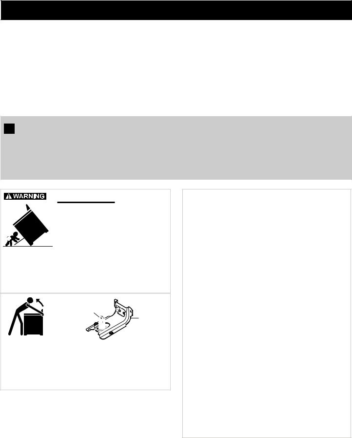
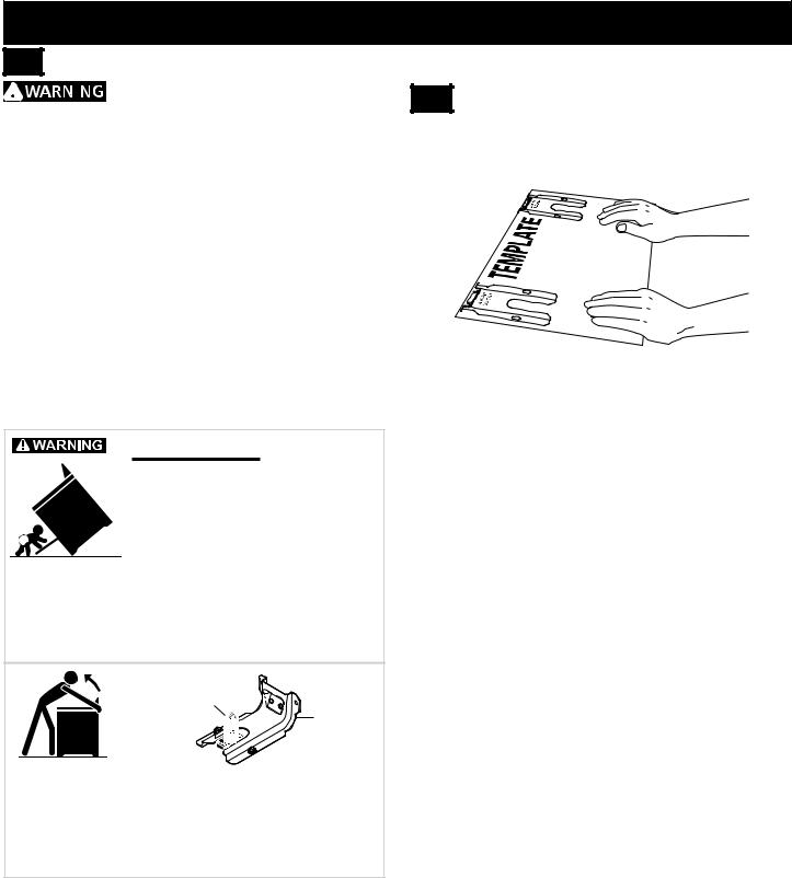
Tip Over Hazard
•A child or adult can tip the range and be killed.
•Verify the anti-tip device has been
installed to floor or wall.
•Ensure the anti-tip device is re-engaged to floor or wall when the range is moved.
•Do not operate the range without the anti-tip device in place and engaged.
•Failure to follow these instructions can result in death or serious burns to children and adults.
Range leveling leg
Anti-tip bracket
To check if the anti-tip bracket is installed properly, use both arms to grasp the rear edge of the range back. Carefully attempt to tilt range forward. When properly installed, the range should not tilt forward.
Refer to the anti-tip bracket installation instructions supplied with your range for proper installation.
 If the information in this manual is not followed exactly, a fire or explosion may result causing property damage, personal injury or death.
FOR YOUR SAFETY:
—Do not store or use gasoline or other flammable vapors and liquids in the vicinity of this or any other appliance. —WHAT TO DO IF YOU SMELL GAS:
•Do not try to light any appliance.
•Do not touch any electrical switch; do not use any phone in your building.
•Immediately call your gas supplier from a neighbor's phone. Follow the gas supplier's instructions.
•If you cannot reach your gas supplier,
call the fire department. —Installation and service must be
performed by a qualified installer, servicer or the gas supplier.
2
36" GAS RANGE INSTALLATION INSTRUCTIONS
•Excessive Weight Hazard--Use two or more people to move and install range. Failure to follow this instruction can result in back or other injury.
•Storage In or On Appliance—Flammable materials should not be stored in an oven or microwave, near surface burners or elements, or in the storage or warmer drawer (if equipped). This includes paper, plastic, and cloth items, such as cookbooks, plastic ware, and towels, as well as flammable liquids. Do not store explosives, such as aerosol cans, on or near the appliance.
•Do not leave children alone - Children should not be left alone or unattended in the area where appliance is in use. They should never be allowed to sit or stand on any part of the appliance, including the storage drawer, lower broiler drawer, warmer drawer, or lower double oven.
•Do not store items of interest to children in the cabinets above the appliance or on the backguards of ranges. Children climbing on or near the appliance to reach items could be seriously injured.
•Stepping, leaning, or sitting on the door or drawers of this appliance can result in serious injuries and also cause damage to the appliance.
•Do not use oven or warmer drawer (if equipped) for storage.
•Never use your appliance as a space heater to heat or warm the room. Doing so may result in carbon monoxide poisoning and overheating of the appliance.
•Do not store or use gasoline or other flammable vapors and liquids in the vicinity of this or any other appliance.
•Never cover any slots, holes, or passages in the oven bottom or cover an entire oven rack with any materials, such as aluminum foil or aftermarket oven liners. Aluminum foil and other liners may trap heat, causing a fire hazard.
•Air curtain or other overhead range hoods which operate by blowing a downward air flow onto a range or cooktop, shall not be used in conjunction with gas ranges or cooktops other than when the range or cooktop and hood have been designed, tested, and listed by an independent test laboratory for use in combination with each other.
IMPORTANT INSTRUCTIONS FOR UNPACKING AND INSTALLATION
Read and follow the below instructions and precautions for unpacking, installing, and servicing your appliance:
•Destroy the carton and plastic bags after unpacking the appliance. Never allow children to play with packaging material. Do not remove the wiring label and other literature attached to the appliance. Do not remove model/serial number plate.
•Cold temperatures can damage the electronic control.
When using this appliance for the first time, or when the appliance has not been used for an extended period of time, be sure the appliance has been in temperatures above 32ºF (0ºC) for at least 3 hours before turning on the power to the appliance.
•Never modify or alter the construction of the appliance by removing the leveling legs, panels, wire covers, antitip brackets/screws, or any other part of the appliance.
•Proper Installation—Be sure your appliance is properly installed and grounded by a qualified technician. In the
United States, install in accordance with the National Fuel Gas Code ANSI Z223.1/NPFA No. 54, latest edition and National Electrical Code NFPA No. 70 latest edition, and local electrical code requirements. In Canada, install in accordance with CAN/CGA B149.1 and CAN/CGA B149.2 and CSA Standard C22.1, Canadian Electrical code, Part 1-latest editions and local electrical code requirements. Install only per installation instructions provided in the literature package for this appliance.
•The installation of appliances designed for manufactured (mobile) home installation must conform with Manufactured Home Construction and Safety Standard, title 24CFR, part 3280 [Formerly the Federal Standard for Mobile Home Construction and Safety, title 24, HUD (part 280)] or when
such standard is not applicable, the Standard for Manufactured Home Installation 1982 (Manufactured Home Sites, Communities and Setups), ANSI Z225.1/ NFPA 501A-latest edition, or with local codes in United States and with CAN/CSA-Z240 MH in Canada.
•Before installing the range in an area covered with linoleum or any other synthetic floor covering, make sure the floor covering can withstand heat at least
90°F (32.2°C) above room temperature without shrinking, warping or discoloring. Do not install the range over carpeting unless you place an insulating pad or sheet of ¼" (0,64 cm) thick plywood between the range and carpeting.
•Make sure the wall coverings and cabinet materials around the range can withstand the heat generated by the appliance.
•To eliminate the risk of burns or fire by reaching over heated surface units, cabinet storage space above the surface unit should be avoided. If cabinet storage is to be provided the risk can be reduce by installing a range hood that projects horizontally a minimum of 5 inches beyond the bottom of the cabinet.
•Do not obstruct airflow at the oven vent, around the base, or beneath the lower front panel of the
appliance. This appliance requires fresh air for proper operation.
•Be sure to have an appropriate foam-type fire extinguisher available, visible, and easily accessible located near the appliance.
3

36" GAS RANGE INSTALLATION INSTRUCTIONS
SPECIAL INSTRUCTIONS FOR APPLIANCES |
IMPORTANT INSTRUCTIONS FOR SERVICE AND |
INSTALLED IN THE STATE OF MASSACHUSETTS |
MAINTENANCE |
This appliance can only be installed in the State of Massachusetts by a Massachusetts licensed plumber or gas fitter. When using a flexible gas connector, it must not exceed 3 feet (36 inches) in length. A "T" handle type manual gas valve must be installed in the gas supply line to this appliance.
CONVERSION TO L.P. GAS
This appliance allows for conversion to Liquefied
Petroleum (L.P.) Gas.
 Personal injury or death from electrical shock may occur if the conversion to L.P. gas is not made by a qualified installer or electrician. Any additions, changes or conversions required in order for this appliance to satisfactorily meet the application needs must be made by a qualified technician.
If L.P. conversion is needed, contact your local L.P. Gas provider for assistance. The L.P. conversion kit is provided with this appliance and is located on the lower REAR (back side) panel of the range. Before installing the kit be sure to read the L.P. Installation Instructions and follow them carefully when making the installation.
•Do not repair or replace any part of the appliance unless specifically recommended in the manuals. All other servicing should be done only by a qualified technician. This reduces the risk of personal injury and damage to the appliance.
•Always contact your dealer, distributor, service agent, or manufacturer about problems or conditions you do not understand.
•Ask your dealer to recommend a qualified technician and an authorized repair service. Know how to disconnect the power to the appliance at the circuit breaker or fuse box in case of an emergency.
•Remove the oven door from any unused oven if it is to be stored or discarded.
•Do not touch a hot oven light bulb with a damp cloth. Doing so could cause the bulb to break. Handle halogen lights (if equipped) with paper towels or soft gloves. Disconnect the appliance or shut off the power to the appliance before removing and replacing the bulb.
4
36" GAS RANGE INSTALLATION INSTRUCTIONS
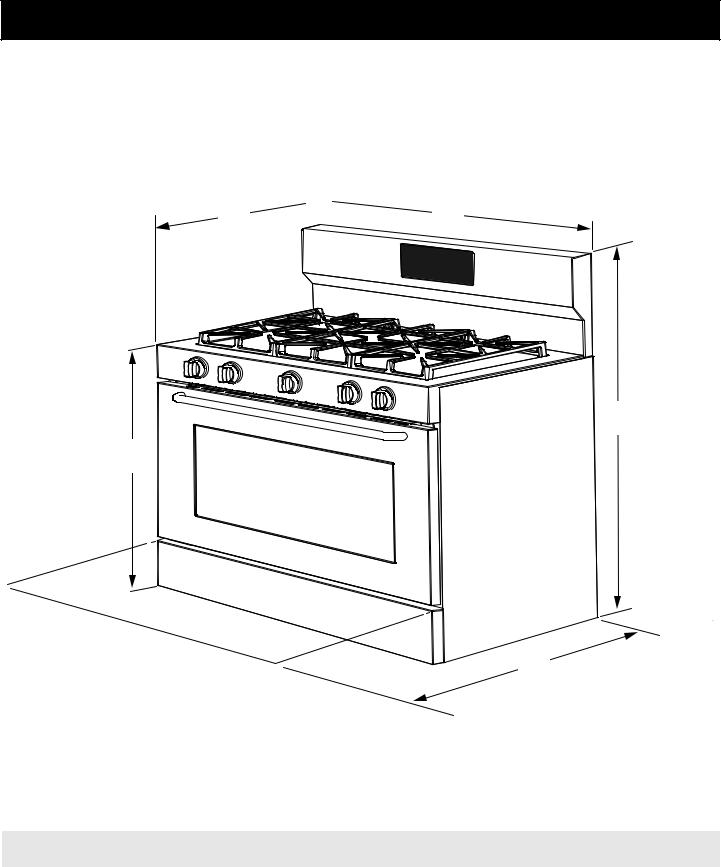
Product Dimensions
 Do not install the unit in the cabinet before reading next two pages.
C 
 B
B
A
D
E
Figure 1: Product Dimensions
MODEL |
A. HEIGHT |
B. WIDTH |
C. DEPTH TO FRONT |
D. HEIGHT OF |
E. DEPTH WITH |
|
OF RANGE |
COOKTOP |
DOOR OPEN |
||||
|
|
|
||||
36" |
49" (124.5cm) Max. |
36" (91.4cm) |
28 1/2" (72.4cm) Max. |
36" (91.4cm) Max. |
47 3/4" (121.3 cm) |
5
36" GAS RANGE INSTALLATION INSTRUCTIONS
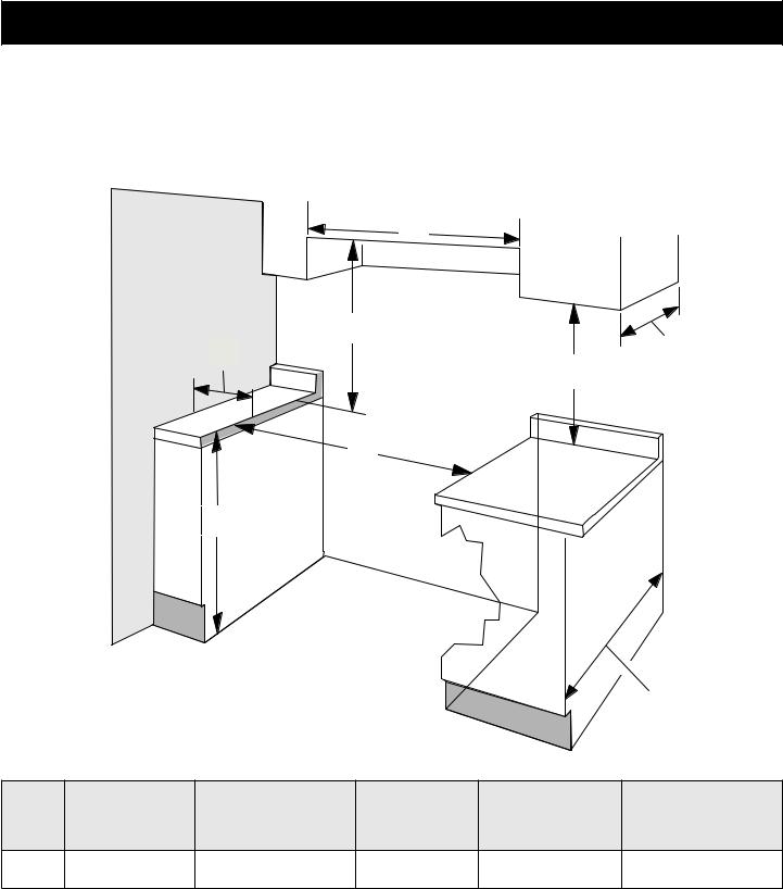
Cabinet Dimensions
Clearances and Dimensions
•Provide adequate clearances between the appliance and adjacent combustible surfaces.
•Location - Check location where the appliance will be installed. Check for proper electrical supply and floor stability.
•Dimensions shown must be used. Given dimensions provide minimum clearance. Contact surface must be solid and level.
J
|
|
H |
I |
|
|
13" Max. |
|
|
|
|
|
18" Min. |
(33 cm Max.) |
||
|
|
|
|
|
|||
|
|
|
|
|
(45.7 cm Min.) |
|
|
|
|
|
F |
|
|
|
|
|
|
G |
|
|
|
|
|
|
|
|
|
|
|
24" Min. |
|
|
|
|
|
|
|
(61 cm Min.) |
|
|
|
|
|
|
|
24½" max. |
|
|
|
Figure 2: Cabinet Dimensions |
(62.2 cm Max.) |
||||
|
|
|
|||||
|
F. MINIMUM |
G. HEIGHT OF |
H. CLEARANCE |
I. CLEARNACE |
J. CLEARANCE |
||
|
FROM COOKTOP |
WIDTH OF |
|||||
MODEL |
FROM SIDE |
||||||
CUTOUT WIDTH |
COUNTERTOP |
AND CABINET |
OVERHEAD |
||||
|
WALLS |
2 |
|||||
|
|
|
|
BOTTOM 3 |
CABINETS |
||
36" |
36 1/4" (92.1cm) |
36" (91.4cm) Standard |
5" (12.7cm) Min. |
36" (91.4cm) Min. |
36" (91.4cm) Min. |
||
35 3/4" (90.8cm) Min. |
|||||||
|
|
|
|
|
|
||
NOTES:
1.Do not seal the range to the side cabinets.
2.Clearance from adjacent walls or other vertical surfaces or structures such as cabinets.
3.Measurements listed are minimum clearance between the cooktop and the bottom of the cabinet.
4.0" clearance between range and cabinets or vertical surfaces that are below the cooktop height.
5.0" clearance between range back and rear wall or cabinet.
6
36" GAS RANGE INSTALLATION INSTRUCTIONS
1 |
Cabinet Construction |
2 Electrical Requirements
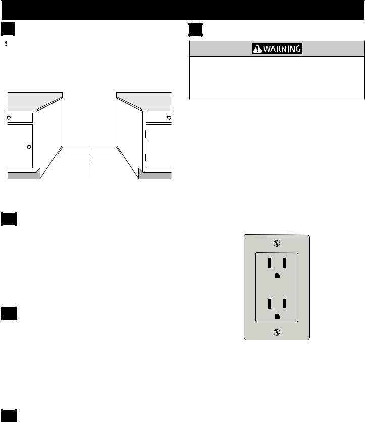
 To eliminate the risk of burns or fire by reaching over heated surface units, do not have cabinet storage space above the range. If there is cabinet storage space above range, reduce risk by installing a range hood that projects horizontally a minimum of 5" (12.7 cm) beyond the bottom of the cabinet.
Center
Line of
Range
Follow instructions for
the type of installation you have
Figure 3: Cabinet construction
1.1 |
Installation: Cabinet on Both Sides |
1.If range will be installed with a cabinet on both sides,
Draw a center line on the floor between the cabinets
(Figure 3).
2.If back of range will not be flush with the wall (the location of the outlet may not allow the range to be positioned against the wall), draw a line on the floor where the back edge of the range will be.
3.Install anti-tip brackets (see "Anti-Tip Bracket Installation").
1.2 |
Installation: Cabinet on One Side Only |
1.If range will be installed with a cabinet on one side only, move the range into final position.
2.Draw a line on the floor along the side of the range that is not against the cabinet. If back of range will not be flush with the wall (the location of the outlet may not allow the range to be positioned against the wall), draw a line on the floor where the back edge of the range will be.
3.Install anti-tip brackets (see "Anti-Tip Bracket Installation").
1.3 |
Installation: Without Cabinet |
1.If range will not be installed against a cabinet, move range into final position.
2.Mark on the floor along both sides of the range. If back of range will not be flush with the wall (the
location of the outlet may not allow the range to be positioned against the wall), draw a line on the floor where the back edge of the range will be.
3.Install anti-tip brackets (see "Anti-Tip Bracket Installation").
Electrical Shock Hazard –Electrical ground is required on this appliance. Use only the power cord supplied with the appliance. Improper connections and grounding may result in electric shock, damage to the appliance, personal injury, fire or death.
Grounding Requirements
This appliance must be installed and grounded by a qualified technician.
In the United States, install in accordance with the National Fuel Gas Code ANSI Z223.1/NPFA No. 54, latest edition and National Electrical Code NFPA No. 70 latest edition, and local electrical code requirements. In Canada, install in accordance with CAN/CGA B149.1 and CAN/CGA B149.2 and CSA Standard C22.1, Canadian Electrical code, Part 1-latest editions and local electrical code requirements.
This appliance requires a dedicated, properly grounded and polarized branch circuit protected by a 15 amp GFI (ground fault interrupter) circuit breaker or time delay fuse. See serial plate for proper voltage.
Figure 4: 3-Prong Gounded Electrical Outlet
For personal safety, this appliance must be properly grounded. For maximum safety, the power cord must be plugged into an electrical outlet that is the correct voltage, is correctly polarized and properly grounded in accordance with local codes. It is the personal responsibility of the consumer to have the appropriate
outlet with the correct, properly grounded wall receptacle installed by a qualified electrician.
Be sure the wall receptacle is within reach of the appliance's final installed location.
Do not pinch the power supply cord between the range and the wall.
7
36" GAS RANGE INSTALLATION INSTRUCTIONS
Recommended Wall Outlet Installation Locations
Suggested location of the wall outlet is shown in Figure 5. The outlet may also be located in the lower corner of the adjacent cabinets, as shown in Figure 6.
3 Power Supply Cord
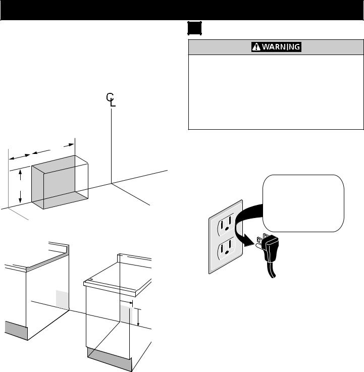
Electrical Shock Hazard –Do not attempt to install the appliance directly to a junction box, modify the factory-installed cord, or connect a different power cord to the appliance. If the wall outlet is not sufficient to support the requirements of this appliance, it is the responsibility of the consumer to have the appropriate outlet installed by an electrician. Improper installation and electrical connections can result in electric shock, damage to the appliance, personal injury, fire, or death.
5" Max. |
8" |
|
20.3 cm |
||
12.7 cm |
||
|
||
|
|
7" Max. 17.8 cm
WALL FLOOR
Figure 5: Outlet location behind range
This appliance is equipped with a 3-prong grounding plug for your protection against shock hazard and should be plugged directly into a properly grounded receptacle. Do not cut or remove the grounding prong from this plug.
Do not, under any circumstances, cut, remove, or bypass the grounding prong.
8”

 (20.3 cm)
 12” (30.5 cm)
Figure 6: Adjacent cabinet outlet location
Figure 7: Factory connected power supply cord
For personal safety, the appliance must be properly grounded. For maximum safety, the power cord must be plugged into an electrical outlet that is correctly polarized and properly grounded.
If a 2-prong wall receptacle is the only available outlet, it is the personal responsibility of the consumer to have it replaced with a properly grounded 3-prong wall receptacle, installed by a qualified technician.
8
36" GAS RANGE INSTALLATION INSTRUCTIONS
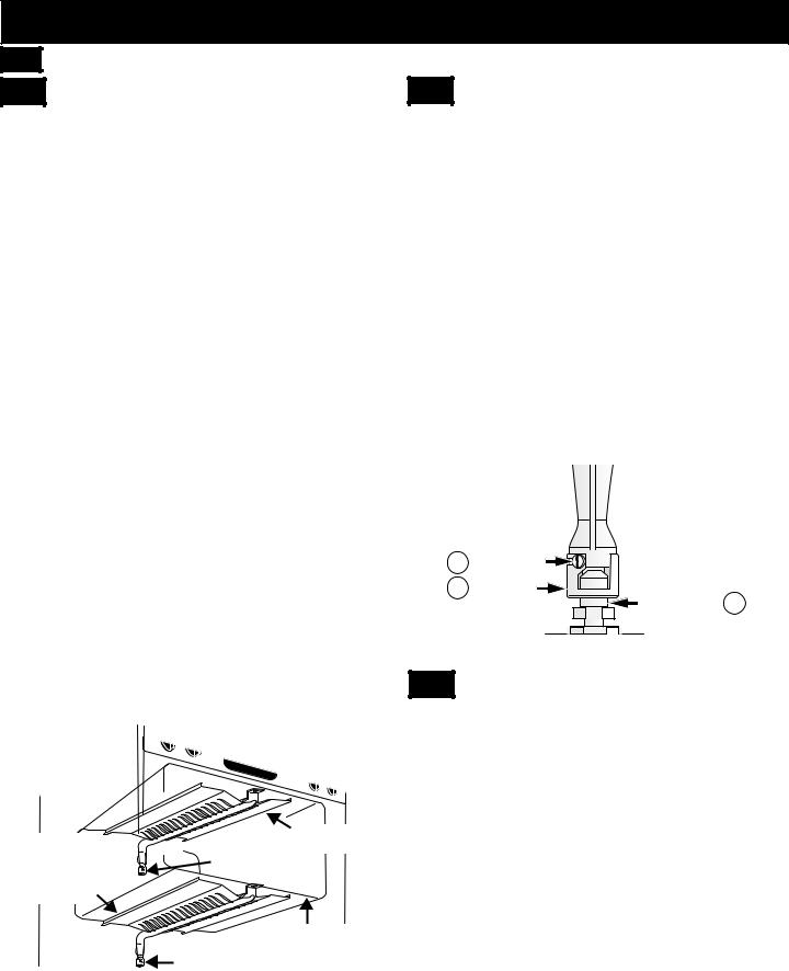
4 Fuel Supply Requirements
This unit is designed to operate on 4"(10.16 cm) water column (1.0 kPa) natural gas manifold pressure.
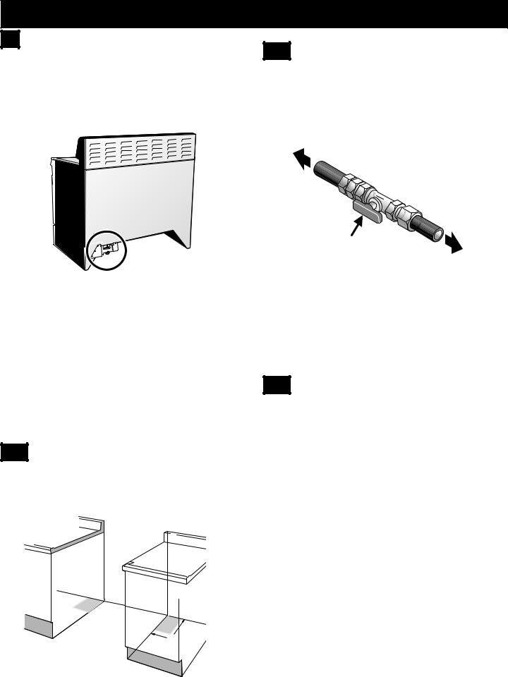
A convertible pressure regulator is connected to the range manifold and MUST be connected in series with the gas supply line. The regulator is located as shown on Figure 8.
Figure 8: Regulator location
For proper operation, the maximum inlet pressure to the regulator should be no more than 14" (35.56 cm) of water column pressure (3.5 kPa).
The inlet pressure to the regulator must be at least 1" (0.25 kPa) greater than the regulator manifold
pressure setting. The regulator is set for 4" (10.16 cm) water column (1.0 kPa) Natural gas manifold pressure; the inlet pressure must be at least 5" (12.60 cm) water column (1.25 kPa) Natural gas.
For operation at 2000 ft. above sea level, appliance rating is reduced by 4 percent for each additional 1000 ft.
4.1 |
Gas Supply Location |
The gas supply piping can be through the side walls of the adjacent cabinets. Cabinets are ideal locations for the main shutoff valve if the appliance is installed between cabinets.
12”
8“ 
 (30.5 cm) (20.3 cm)
4.2 |
Shutoff Valve |
The supply line should be equipped with an approved shutoff valve as shown in Figure 10. This valve should be located in the same room as the range and should be in a location that allows ease of opening and closing. Do not block access to the shutoff valve. The valve is for turning on or shutting off gas to the appliance.
to |
|
|
appliance |
|
|
|
to |
|
|
gas |
suppl |
|
|
|
|
|
y |
Shutoff Valve - |
|
line |
|
|
|
Open position |
|
|
Figure 10: Shutoff valve
The gas supply between the shutoff valve and the regulator may be connected by rigid piping or by A.G.A./
C.G.A.- approved flexible metallic union-connected piping where local codes permit use.
The user must know the location of the main shutoff valve and have easy access to it.
4.3 Conversion to Liquefied Petroleum |
(L.P.) Gas |
This appliance allows for conversion to Liquefied
Petroleum (L.P.) Gas.
 Personal injury or death from electrical shock may occur if the conversion to L.P. gas is not made by a qualified installer or electrician. Any additions, changes or conversions required in order for this appliance to satisfactorily meet the application needs must be made by a qualified technician.
If L.P. conversion is needed, contact your local L.P. Gas provider for assistance. The L.P. conversion kit is provided with this appliance and is located on the lower REAR (back side) panel of the range. Before installing the kit be sure to read the L.P. Installation Instructions and follow them carefully when making the installation.
For LP/Propane gas, the regulator must be set for 10"(25.4 cm) water column (2.5 kPa) manifold pressure; the inlet pressure must be at least 11"(27.9 cm) water column (2.75 kPa).
Figure 9: Recommended gas supply location
9
36" GAS RANGE INSTALLATION INSTRUCTIONS
5 Connect Fuel Supply
5.1 |
Fuel Supply Connection |
 This appliance must be installed, grounded, and serviced by a qualified installer or service technician.
 Do not make connections too tight. The regulator is die cast. Overtightening may crack the regulator resulting in a gas leak and possible fire or explosion.
This appliance includes a regulator. The gas supply line requires the following parts which are not supplied with the appliance:
•Manual shutoff valve
•1/2" nipples (2)
•1/2" flare union adapter (2)
•Flexible connector
The gas supply line to the shutoff valve should be 1/2"(1.27 cm) or 3/4"(1.9 cm) solid pipe.
Install the gas supply pipe to the pressure regulator in the order shown in Figure 11. All connections should be tightened with a wrench.
Manual |
|
|
GAS FLO |
Flare |
Pressure |
||
Shutoff |
Flare |
Regulator |
|||||
Union |
Union |
||||||
Valve |
|
|
|
|
|
|
|
|
|
|
|
|
|
||
|
|
|
|
|
|
|
|
|
|
|
|
|
|
|
|
|
|
|
|
|
|
|
|
On
Nipple |
Flexible |
Nipple |
Access |
Off |
Connector |
|
|
|
|
Cap |
|
|
|
|
Figure 11: Fuel supply connection flow
When using flexible gas conduit on the range, allow sufficient slack to pull the range outside the cutout for cleaning or servicing.
Use pipe-joint compound made for use with Natural and
LP/Propane gas to seal all gas connections. If flexible connectors are used, be certain connectors are not kinked.
Do not allow the flexible conduit to get pinched between the wall and the range.
5.2 |
Check For Leaks |
 Do not use a flame to check for leaks from gas connections. Checking for leaks with a flame may result in a fire or explosion.
After connecting the range to the gas supply, check the system for leaks with a manometer. If a manometer is not available, turn on the gas supply and use a liquid leak detector (or soap and water) at all joints and connections to check for leaks. Leaks will be indicated by bubbles appearing at the connections or joints.
All openings in the wall or floor where the range is to be installed must be sealed.
1.Tighten all connections if necessary to prevent gas leakage in the cooktop or supply line.
2.Disconnect this range and its individual shutoff valve from the gas supply piping system during any pressure testing of the system at test pressures greater than 1/2 psig (3.5 kPa or 14"(35.56 cm) water column).
3.Isolate the range from the gas supply piping system by closing its individual manual shutoff valve during any pressure testing of the gas supply piping system at test pressures equal to or less than 1/2 psig (3.5 kPa or 14"(35.56 cm) water column).
10

36" GAS RANGE INSTALLATION INSTRUCTIONS
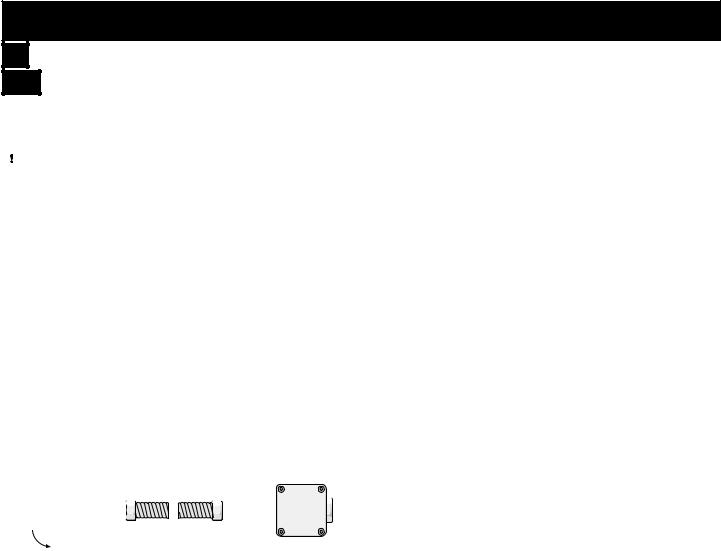
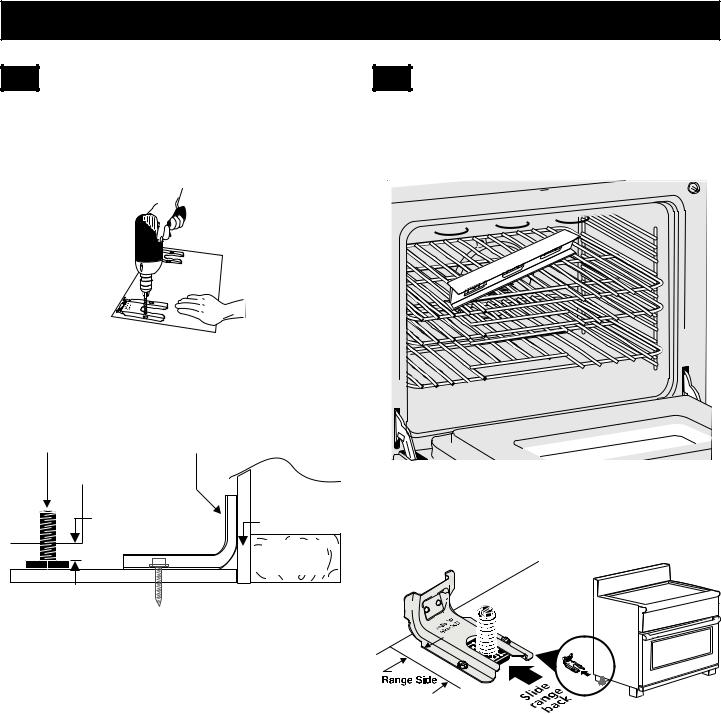
6 Install the Oven Racks
The oven racks are supported inside the oven cavity by two ladder racks, installed on the oven walls.
1.Place the ladder racks hook-side up into the support brackets located on the oven sides (see Figure 12).
7 |
Level the Range |
Level the range and set cooktop height before installation in the cut-out opening (if applicable).
1.Install an oven rack in the center of the oven.
2.Place a level on the rack (Figure 13). Take two readings with the level placed diagonally in one direction and then the other.
Figure 12: Ladder rack supports
2. Place the flat oven racks into the desired positions.
To aid installation and movement of oven racks, apply a thin layer of cooking oil to the sides of the oven racks that contact the ladder supports.
Figure 13: Use the oven racks to level appliance
3.Level the range, if necessary, by adjusting the four leg levelers with a wrench (Figure 14).
4.Slide range into cut-out opening and double check for levelness. If the range is not level, pull unit out and readjust leveling legs, or make sure floor is level.
Leg
Leveler
Raise 
Lower
Figure 14: Adjusting appliance height
11
36" GAS RANGE INSTALLATION INSTRUCTIONS
8 |
Install Anti-Tip Bracket |

 To reduce the risk of tipping the appliance, the appliance must be secured to the floor by the properly installed anti-tip bracket and screws packed with the range. These parts are located in the oven. Failure to install the anti-tip bracket will allow the range to tip over if excessive weight is placed on an open door or if a child climbs on it. Serious injury might result from spilled hot liquids or from the range itself.
If range is ever moved to a different location, the antitip brackets must also be moved and installed with the range.
Tools Required:
•Adjustable Wrench
•Ratchet
•Drill & 1/8" (0.32 cm) bit
•5/16" (0.8 cm) Nut driver
•Level
Tip Over Hazard
•A child or adult can tip the range and be killed.
•Verify the anti-tip device has been
installed to floor or wall.
•Ensure the anti-tip device is re-engaged to floor or wall when the range is moved.
•Do not operate the range without the anti-tip device in place and engaged.
•Failure to follow these instructions can result in death or serious burns to children and adults.
Range leveling leg
Anti-tip bracket
To check if the anti-tip bracket is installed properly, use both arms to grasp the rear edge of the range back. Carefully attempt to tilt range forward. When properly installed, the range should not tilt forward.
Refer to the anti-tip bracket installation instructions supplied with your range for proper installation.
8.1 |
Locate the Bracket Using the Template |
Bracket may be located on either the left or right side of the range. Mark the floor or wall where left or right side of the range will be located.
Figure 15: Bracket template
If rear of range is against the wall or no further than 1 1/4” (3.2 cm) from wall when installed, you may use the wall or floor mount method. If moulding is installed and does not allow the bracket to fit flush against the wall, remove moulding or mount bracket to the floor.
For wall mount, locate the bracket by placing the back edge of the template against the rear wall and the side edge of template on the mark made referencing the side of the range. Place bracket on top of template and mark location of the screw holes in wall.
If rear of range is further than 1 1/4” (3.2 cm) from the wall when installed, attach bracket to the floor. For floor mount, locate the bracket by placing back edge of the template where the rear of the range will be located.
Mark the location of the screw holes shown in template.
12
36" GAS RANGE INSTALLATION INSTRUCTIONS
8.2 |
Drill Pilot Holes and Fasten Bracket |
Drill a 1/8” pilot hole where screws are to be located. If bracket is to be mounted to the wall, drill pilot hole at an approximate 20° downward angle. If bracket is to be mounted to masonry or ceramic floors, drill a 3/16”
(4.8 mm) pilot hole 1-3/4” deep.
8.3 |
Check Level and Position the Range |
Check the level of the final installation. Note: A minimum clearance of 1/8” is required between the bottom of the range and the levelling leg to allow room for the bracket. Use a spirit level to check your adjustments.
Figure 16: Drill pilot holes
The screws provided may be used in wood or concrete material. Use a 5/16” nut-driver or flat head screwdriver to secure the bracket in place.
Leveling Leg |
Anti-Tip Bracket |
1/8" Minimum |
Wall Mount |
|
 Wall Plate
Floor Mount 
Figure 17: Fastening the bracket
Figure 18: Use the oven racks to level appliance
Slide range into position.
Figure 19: Slide appliance into bracket
To check if the anti-tip bracket is installed properly, use both arms and grasp the rear edge of range back. Carefully attempt to tilt range forward. When properly installed, the range should not tilt forward.
If range is moved to a different location, the anti-tip brackets must also be moved and installed with the range.
13

36" GAS RANGE INSTALLATION INSTRUCTIONS
9 |
Prepare Burner Assemblies |
9.1 |
Install Burner Caps |
 To prevent flare-ups use the cooktop with all burner caps properly installed.
1.Place a burner cap on each burner head, matching the cap size to the head size (see Figure 20). The cap for each burner has an inner locating ring which centers the cap correctly on the burner head.
 Burner cap
 Locating ring
Burner head
To check for proper lighting:
1.Push in and turn a surface burner knob to the sparking position. All electronic surface ignitors will spark at the same time. Only the burner you are turning on will ignite.
2.The surface burner should light once the flow of gas reached the surface burner. Each burner should light within four seconds in normal operation after air has been purged from supply lines. Visually check that burner has lit.
3.Once the burner lights, the control knob should be turned out of the LITE position.
Turn on each of the surface burners and check to see that they light properly and that the flames are even.
Adjust settings if necessary.
Burner cap
Burner head
Figure 20: Burner cap assembly
2.Make sure each burner cap is properly aligned and level, as shown in Figure 21. Burners may not light or burn evenly if the burner caps are not correctly place on the head.
9.3 Adjusting Low Settings on |
Surface Burners |
To adjust the low setting of surface burners:
1.Push in and turn control to LITE until burner ignites.
2.Quickly turn knob to LOWEST POSITION.
3.If burner goes out, reset control to OFF.
4.Remove the surface burner control knob.
5.Insert a thin-bladed screwdriver into the hollow valve stem and engage the slotted screw inside as shown in Figure 22. Flame size can be increased or decreased by turning the screw.
6.Adjust flame until you can quickly turn knob from the
Correct cap placement |
Incorrect cap placement |
Figure 21: Burner cap placement
9.2 Check Ignition on Surface |
Burners |
Operation of electric igniters should be checked after range and supply line connectors have been carefully checked for leaks and range has been connected to electric power.
Figure 22: Turn to adjust surface flame
sparking position to the lowest flame position without extinguishing the flame. Flame should be as small as possible without going out.
Notes:
•Air mixture adjustment is not required on surface burners.
•Some models have two flames on a burner. The center flame on these burners is not adjustable.
14
36" GAS RANGE INSTALLATION INSTRUCTIONS
10 Adjusting Oven Burners
10.1 Electric Ignition Burners
Operation of electric igniters should be checked after range and supply line connectors have been carefully checked for leaks, and range has been connected to electric power. The oven burner is equipped with an electric control system as well as an electric oven burner igniter. If your model is equipped with a waist-high broil burner igniter, it will also have an electric burner igniter. These control systems require no adjustment. When
the oven is set to operate, current will flow to the igniter.
It will "glow" similar to a light bulb. When the igniter has reached a temperature sufficient to ignite gas, the
electrically controlled oven valve will open and flame will appear at the oven burner. There is a time lapse from 30 to 60 seconds after thermostat is turned ON before the flame appears at the oven burner. When the oven reaches the display setting, the glowing igniter will go off. The burner flame will go "out" in 20 to 30 seconds after igniter goes "OFF". To maintain any given oven temperature, this cycle will continue as long as the display is set to operate.
After removing all packing materials and literature from the oven:
1.Set the oven to BAKE at 300°F. See Use & Care Guide for operating instructions.
2.Within 60 seconds the oven burner should ignite.
Check for proper flame (see 10.2), and allow the burner to cycle once. Reset controls to off.
3.If your model is equipped with a waist-high broiler burner, set oven to broil. See Use & Care Guide for operating instructions.
4.Within 60 seconds the broil burner should ignite.
Check for proper flame. Reset controls to off.
Lower |
|
Waist-High Burner |
|
Air Shutter |
|||
Oven Burner |
|||
Baffle |
|
|
|
(removable) |
|
|
|
|
|
Lower Oven |
|
|
|
Bottom |
|
|
Air Shutter |
removable) |
|
Figure 23: Oven Burners
10.2 |
Oven Burner Flame Adjustment |
The approximate oven burner flame length is 1 inch (distinct inner cone of blue flame).
To determine if the oven burner flame is proper, remove the oven bottom and burner baffle and set the oven to bake at 300°F.
To remove the oven bottom, remove the oven racks and the ladder racks. Slide the oven bottom forward to disengage the back tab. Lift and slide back to disengage
front of oven bottom from oven front frame. Pull the oven bottom out of the cavity. The baffle is attached to the oven bottom and requires no further disassembly.
If the flame is yellow, increase air shutter opening size (see "2" in Figure 24). If the entire flame is blue, reduce the air shutter opening size.
To adjust flame loosen lock screw (see "3" in Figure 24), reposition air shutter, and tighten lock screw. Replace oven bottom.
 Oven Burner Tube
3 |
Lock Screw |
|
2 Air Shutter |
1 |
|
|
Orifice Hood |
|
Figure 24: Oven Burner Adjustments
10.3 |
Broil Burner Flame Adjustment |
The approximate flame length of the burner is 1 inch (distinct inner cone of blue flame). To determine if the broil burner flame is proper, set the oven to broil. If flame is yellow, increase air shutter opening size (see "2" in
Figure 24). If the entire flame is blue, reduce the air shutter opening size. To adjust, loosen lock screw (see "3" in Figure 24), reposition air shutter, and tighten lock screw.
15
 Loading...