


INSTALLATION INSTRUCTIONS 30" GAS SLIDE-IN RANGE
INSTALLATION AND SERVICE MUST BE PERFORMED BY A QUALIFIED INSTALLER. IMPORTANT: SAVE FOR LOCAL ELECTRICAL INSPECTOR'S USE.
READ AND SAVE THESE INSTRUCTIONS FOR FUTURE REFERENCE.
United States
Canada
Refer to your serial plate for applicable agency certification.


 If the information in this manual is not followed exactly, a fire or explosion may result causing property damage, personal injury or death.
FOR YOUR SAFETY:
—Do not store or use gasoline or other flammable vapors and liquids in the vicinity of this or any other appliance.
—WHAT TO DO IF YOU SMELL GAS:
•Do not try to light any appliance.
•Do not touch any electrical switch; do not use any phone in your building.
•Immediately call your gas supplier from a neighbor's phone. Follow the gas supplier's instructions.
• If you cannot reach your gas supplier, call the fire department.
—Installation and service must be performed by a qualified installer, service agency or the gas supplier.
Table of Contents |
|
Important Safety Instructions.......................................... |
2 |
Product & Cabinet Dimensions.................................... |
3-4 |
To Avoid Breakage.......................................................... |
5 |
Before Starting................................................................ |
6 |
Cabinet Construction.................................................... |
6-7 |
Provide an Adequate Gas Supply................................... |
7 |
Seal the Openings........................................................... |
7 |
Connect the Range to the Gas Supply......................... |
7-8 |
LP/Propane Gas Conversion.......................................... |
8 |
Electrical Requirements.................................................. |
8 |
Moving the Appliance for servicing and Cleaning. |
.......... 8 |
Range Installation........................................................... |
9 |
Leveling the Range....................................................... |
10 |
Decorative Rear Trim Installation.................................. |
10 |
Check Operation...................................................... |
11 - 12 |
When All Hookups are Complete.................................. |
12 |
Model and Serial Number Location............................... |
12 |
Before You Call for Service........................................... |
12 |
Anti-Tip Brackets Installation.................................... |
13 - 14 |
Notes............................................................................. |
44 |
Important Notes to the Installer |
Appliances Installed in the state of |
||
1. |
Read all instructions contained in these installation |
Massachusetts: |
|
|
instructions before installing range. |
This Appliance can only be installed in the state of |
|
2. |
Remove all packing material from the oven and the |
Massachusetts by a Massachusetts licensed plumber or |
|
|
drawer compartments before connecting the gas and |
gasfitter. |
|
|
electrical supply to the range. |
This appliance must be installed with a three (3) foot / 36 |
|
3. |
Observe all governing codes and ordinances. |
||
in. long flexible gas connector. |
|||
4. |
Be sure to leave these instructions with the consumer. |
||
A"T" handle type manual gas valve must be installed in |
|||
5. |
Note: For operation at 2000 ft. elevations above see |
||
|
level, appliance rating shall be reduced by 4 percent for |
the gas supply line to this appliance. |
|
|
each additional 1000 ft. |
|
|
Important Note to the Consumer |
|
Cold temperature can damage the |
electronic control. When using the appliance for the |
||
Keep these instructions with your owner's guide for the |
first time, or when the appliance has not been used |
|
local electrical inspector's use and future reference. |
for an extended period, be certain the unit has been |
|
|
in temperatures above 32°F (0°C) for at least 3 hours |
||
P/N 318201697 (1304) Rev. A |
before turning on the power to the appliance. |
||
|
Printed in United States |
||
English – pages 1-14; Spanish - pages 15-28; French – pages 29-44 |
|||
|
|||

30" GAS SLIDE-IN RANGE INSTALLATION INSTRUCTIONS
(Models with Sealed Top Burners)
IMPORTANT SAFETY INSTRUCTIONS
This manual contains important safety symbols and instructions. Please pay attention to these symbols and follow all instructions given.


 This symbol will help alert you to situations that may cause serious bodily harm, death or property damage.


 This symbol will help alert you to situations that may cause bodily injury or property damage.
Installation of this range must conform with local codes or, in the absence of local codes, with the National Fuel Gas Code ANSI Z223.1/NFPA .54-latest edition or CAN/ ACGB149.1 and CAN/ACG - B149.2.
ThisrangehasbeendesigncertifiedbyCSAInternational.
As with any appliance using gas and generating heat, there are certain safety precautions you should follow. You will find them in the Use and Care Guide, read it carefully.
•Be sure your range is installed and grounded properly by a qualified installer or service technician.
•This range must be electrically grounded in accordance with local codes or, in their absence, with the National Electrical Code ANSI/NFPA No. 70—latest edition in United States or with CSA Standard C22.1, Canadian Electrical Code, Part 1 in Canada. See Grounding Instructions.
•Air curtain or other overhead hoods, which operate by blowing a downward air flow on to a range, shall not be used in conjunction with gas ranges other than when the hood and range have been designed, tested and listen by an independent test laboratory for use in combination with each other.
•Before installing the range in an area covered with linoleum or any other synthetic floor covering, make sure the floor covering can withstand heat at least 90°F above room temperature without shrinking, warping or discoloring. Do not install the range over carpeting unless you place an insulating pad or sheet of ¼" (0,64 cm) thick plywood between the range and carpeting.
•Make sure the wall coverings around the range can withstand the heat generated by the range.
•Do not obstruct the flow of combustion air at the oven vent nor around the base or beneath the lower front panel of the range. Avoid touching the vent openings or nearby surfaces as they may become hot while the oven is in operation. This range requires fresh air for proper burner combustion.
 Never leave children alone or unattended in the area where an appliance is in use.
As children grow, teach them the proper, safe use of all appliances. Never leave the oven door open when the range is unattended.
 Stepping, leaning or sitting on the doors or drawers of this range can result in serious injuries and can also cause damage to the range.
•Do not store items of interest to children in the cabinets above the range. Children could be seriously
2
burned climbing on the range to reach items.
•To eliminate the need to reach over the surface burners, cabinet storage space above the burners should be avoided.
•Adjust surface burner flame size so it does not extend beyond the edge of the cooking utensil.
Excessive flame is hazardous.
•Do not use the oven as a storage space. This creates a potentially hazardous situation.
•Never use your range for warming or heating the room. Prolonged use of the range without adequate ventilation can be dangerous.
•Do not store or use gasoline or other flammable vapors and liquids near this or any other appliance.
Explosions or fires could result.
•In the event of an electrical power outage, the surface burners can be lit manually. To light a surface burner, hold a lit match to the burner head and slowly turn the Surface Control knob to LITE. Use caution when lighting surface burners manually.
•Reset all controls to the "off" position after using a programmable timing operation.
FOR MODELS WITH SELF-CLEAN FEATURE:
•Remove broiler pan, food and other utensils before self-cleaning the oven. Wipe up excess spillage. Follow the precleaning instructions in the Use and Care Guide.
•Unlike the standard gas range, THIS COOKTOP IS NOT REMOVABLE. Do not attempt to remove the cooktop.


 Tip Over Hazard
•A child or adult can tip the range and be killed.
•Verify the anti-tip device has been
installed to floor or wall as per installation instructions.
•Ensure the anti-tip device is re-engaged to floor or wall when the range is moved.
•Do not operate the range without the anti-tip device in place and engaged.
•Failure to follow these instructions can result in death or serious burns to children and adults.
To check if the anti-tip bracket is installed properly, use both arms and grasp
the rear edge of range back. Carefully attempt to tilt range forward. When properly installed, the range should not tilt forward.
Refer to the anti-tip bracket installation instructions supplied with your range for proper installation.
30" GAS SLIDE-IN RANGE INSTALLATION INSTRUCTIONS
(Models with Sealed Top Burners)
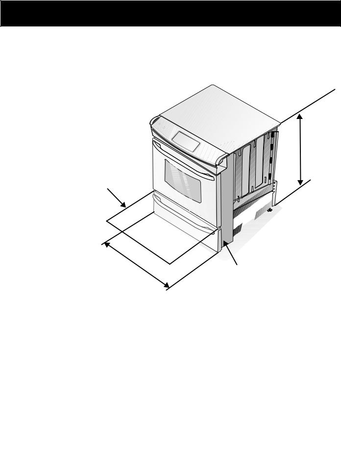
Product Dimensions


 Do not install the unit in the cabinet before reading next two pages.
Door Open (see note 5)
21¾”
(55.25 cm)
C
A

 D
D
B
Side Panel
A. HEIGHT |
B. |
C. |
D. TOTAL DEPTH |
E. CUTOUT WIDTH |
F. CUTOUT DEPTH |
G. HEIGHT |
(Under Cooktop) |
WIDTH |
COOKTOP |
TO FRONT OF |
(Countertop and |
|
OF COUNTERTOP |
|
|
WIDTH |
RANGE |
cabinet) |
|
|
35 7/8" (91,1 cm) |
30" |
31 ½" |
28 5/16" |
30±1/16" |
21 3/4" (55,2 cm) Min. |
36 5/8" (93 cm) Max. |
36 5/8" (93 cm) |
(76,2 cm) |
(80 cm) |
(71,9 cm) |
(76,2±0,15 cm) |
22 1/8" (56,2 cm) Max |
35 7/8" (91,1 cm) Min. |
|
|
|
|
|
24" (61 cm) Min. with |
|
|
|
|
|
|
backguard |
|
NOTES:
1Do not pinch the power supply cord or the flexible gas conduit between the range and the wall.
2Do not seal the range to the side cabinets.
324" (61 cm) minimum clearance between the cooktop and the bottom of the cabinet when the bottom of wood or metal cabinet is protected by not less than 1/4" (0,64 cm) flame retardant millboard covered with not less than No. 28 MSG sheet metal, 0,015" (0,4 mm) stainless steel,
0,024" (0,6 mm) aluminum, or 0,020" (0,5 mm) copper.
30" (76,2 cm) minimum clearance when the cabinet is unprotected.
4For cutouts below 22 7/8" (58,1 cm), appliance will slightly show out of the cabinet.
5Allow at least 19 ¼" (48.9 cm) clearance for door depth when it is open.
3
30" GAS SLIDE-IN RANGE INSTALLATION INSTRUCTIONS
(Models with Sealed Top Burners)
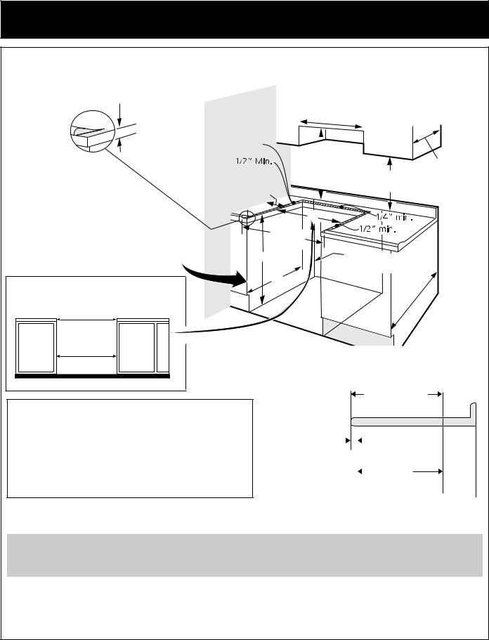
Cabinet Dimensions
Shave |
1 ½" Max. |
Raised Edge |
(3,8 cm Max.) |
to Clear |
|
Space for a |
|
311/2" min (80 |
|
cm) Wide |
|
Cooktop. |
|
See |
|
Dimension C |
|
in table. |
|
|
|
WALL
These surfaces should be flat & leveled
(hatched area).
5" Min. (12,7 cm Min.) From Wall Both Sides
|
30" Min. |
|
|
|||||
|
(76,2 cm |
Min.) |
|
|
||||
|
|
|||||||
30" |
|
|
Min. |
|
|
13" |
||
|
|
|
|
|||||
|
|
|
|
|||||
|
|
|
|
|||||
(76,2 |
cm) Min. |
|
||||||
|
(33 cm) |
|||||||
(see |
page 3, |
18" Min. |
||||||
|
||||||||
|
note 3) |
|
|
|||||
|
(45,7 cm) Min. |
|
||||||
|
|
|
|
|
|
|||
|
|
|
|
|
|
|
|
|
Locate Cabinet Doors 1" (2,5 cm) Min. from Cutout Opening.
IMPORTANT: Cabinet and countertop width should match the cutout width.
E
|
E |
31 1/2" |
|
(80 cm) |
|
G Exact |
Approx. 1 7/8" |
F |
(4,8 cm) |
|
 24" Min.
(61 cm Min.)
E
*IMPORTANT: To avoid cooktop breakage for cutout width (E dimension) of more than 30 1/16" (76,4 cm), make sure the appliance is centered in the counter opening while pushing into it. Raise leveling legs at a higher position than the cabinet height (see page 5), insert the appliance in the counter and then level. Make sure the unit is supported by the leveling legs and
NOT by the cooktop itself.
22 7/8" (58,1 cm) min.
23 1/4" (59,05 cm) max.
(see page 3, note 4)
|
|
|
1 1/8" |
|||
|
|
|
|
|
(2,86 cm) |
|
FRONT |
|
|
|
FRef. |
||
OF |
|
|
|
|||
CABINET |
|
|
|
|
||
 Do not install the unit in the cabinet before reading next these 2 pages.
A. HEIGHT |
|
C. |
D. TOTAL |
E. CUTOUT WIDTH |
|
G. HEIGHT |
|
B. WIDTH |
DEPTH TO |
F. CUTOUT DEPTH |
|||||
COOKTOP |
(Countertop and |
||||||
(Under Cooktop) |
FRONT OF |
OF COUNTERTOP |
|||||
|
|
WIDTH |
RANGE |
cabinet)* |
|
|
|
|
|
|
|
|
|
||
|
|
|
|
|
21 3/4" (55,2 cm) Min. |
|
|
35 7/8" (91,1 cm) |
30" |
31 ½" |
28 5/16" |
30±1/16" |
22 1/8" (56,2 cm) Max |
36 5/8" (93 cm) Max. |
|
36 5/8" (93 cm) |
(76,2 cm) |
(80 cm) |
(71,9 cm) |
(76,2±0,15 cm) |
24" (61 cm) Min. with |
35 7/8" (91,1 cm) |
|
|
|
|
|
|
backguard |
|
NOTE: Wiring diagram for these appliances are enclosed in this booklet.
4

30" GAS SLIDE-IN RANGE INSTALLATION INSTRUCTIONS
(Models with Sealed Top Burners)
To avoid breakage: Do NOT handle or manipulate the unit by the cooktop.
1 The counter-top around the cut-out should be flat and leveled (see hatched area on illustration 1).
2 |
Before installing the unit, measure the heights of the two (2) cabinet |
|
|
|
sides (H1-4), front and back (see illustration 1) from the floor to the |
|
|
3 |
top of the counter. |
1 ½" Max. |
|
Level the range using the |
|
||
(3,8 cm Max.) |
|
||
|
leveling legs or leveling device |
|
H2 |
|
so that the height from the |
|
|
|
floor to the underside of the |
H1 |
H4 |
|
|
||
|
cooktop frame is greater than |
Shave Raised Edge |
|
|
the tallest cabinet measurement |
H3 |
|
|
by at least 1/16" (0,16 cm) (see |
to Clear Space for |
|
|
a 31½" (80 cm) |
|
|
|
illustration 2). |
|
|
4 |
Wide Cooktop. |
|
|
Model equipped with leveling |
Illustration 1 |
|
|
|
device: Remove and discard the two rear leveling legs, they are only in place to |
||
solidify the unit during the transport.
5
6
Slide the unit into the cabinet. Make sure the center of the unit is ali gned with the center of the cabinet cut-out.


Remove the protective channels on each side of cookto p (i
p (i
 f
f


 equipped).


7 The metal flange under each side of the cooktop MUST be placed


 over the cabinet countertop for proper unit support. The cooktop


should NOT directly touch the countertop (see illustration 2) or else it could cause damage to the cooktop
voiding the warranty. Level the unit if needed.
8 After the installation,
MAKE SURE |
|
|
that the unit is |
|
|
supported by the |
Illustration 2 |
|
leveling legs NOT |
||
|
||
by the cooktop. |
|
Metal
Flange
To successfully install the range, the initial level height from floor to underside of cooktop
frame should be at least 1/16" (0,16 cm) taller than cabinet sides as measured in step 2.
5
30" GAS SLIDE-IN RANGE INSTALLATION INSTRUCTIONS
(Models with Sealed Top Burners)
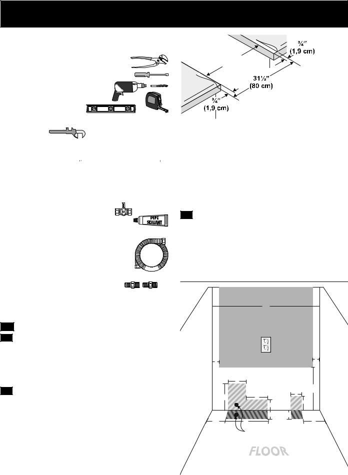
Before Starting
Tools you will need
For leveling legs and anti-tip brackets:
●Adjustable wrench or channel lock pliers 
●5/16" Nutdriver or Flat Head Screw Driver 
● Electric Drill & 1/8 Diameter
Drill Bit (5/32" Masonry Drill Bit if installing in concrete)
● Level & Measuring Tape
For gas supply connection:
● Pipe Wrench  ● Brush

For burner flame adjustment:
●Phillips head 
 and blade-type
  screwdrivers
For gas conversion (LP/Propane or Natural):
● Open end wrench - 1/2" 
Additional materials you will need:
● Gas line shut-off valve
● Pipe joint sealant that resists action of LP/Propane gas
● A new flexible metal appliance conduit
(½" NPT x ¾" or ½" I.D.) must be design certified by CSA International. Because solid pipe restricts moving the range we recommend using a new flexible conduit
(4 feet length) for each new installation and 


 additional reinstallations.
● Always use the (2) new flare union
adapters ½" NPT x ¾" or ½" I.D.) supplied with the new flexible appliance conduit for connection of the range.
1. Cabinet Construction
1.1  To eliminate the risk of cabinet
burns and fire, do not have cabinet storage space above the range. If there is cabinet storage space above range, reduce risk by installing a range hood that projects horizontally a minimum of 5" (12,7 cm) beyond the bottom of the cabinet.
1.2Countertop Preparation (figure 1)
•The cooktop sides of the range fit over the cutout edge of your countertop.
•If you have a square finish (flat) countertop, no countertop preparation is required. Cooktop sides lay directly on edge of countertop.
•Formed front-edged countertops must have molded edge shaved flat 3/4" (1,9 cm) from each front corner of opening (Figure 1).
•Tile countertops may need trim cut back 3/4"(1,9 cm) from each front corner and/or rounded edge flattened (Figure 1).
Min. |
Cutout |
Width |
Formed or tile |
countertop trimmed ¾" |
(1,9 cm) back at front |
corners of countertop |
opening. |
Figure 1 |
•If the existing cutout width is greater than 30-1/16" (76,4 cm), reduce the ¾" (1,9 cm) dimension.
•Countertop must be level. Place a level on the countertop, first side to side, then front to back. If the countertop is not level, the range will not be level. The oven must be level for satisfactory baking results. Cooktop sides of range fit over edges of countertop opening.
1.3Gas and Electric Entry Preparation
•The hatched areas are the locations where the gas line can enter the cabinet (figure 2).
•The recommended position for the gas entry line is located at 7" (17,8 cm) from the left cabinet wall and
2" (5,1 cm) from the floor (figure 2).
•The shaded area is the location where the electric outlet can be located (figure 2).
|
|
30 |
|
|
|
|
|
(76.2) |
|
|
|
|
2 |
|
|
(52.1) |
|
|
(5.1) |
|
|
|
|
ALL |
|
5 |
|
W |
|
|
|
12 |
|
||
|
|
|
|
||
|
|
3 |
(30.5) |
ALL |
|
7½ |
6 |
|
|||
W |
|
4 |
|
||
|
3 |
|
|
||
|
|
|
|
||
|
2½ |
2½ |
|
|
|
|
4.5 |
|
|
||
|
11 |
|
5 |
|
|
|
|
Recommended |
|
|
|
|
|
position |
|
|
|
Note: All dimensions are in inches (centimeter).
Figure 2
6
30" GAS SLIDE-IN RANGE INSTALLATION INSTRUCTIONS
(Models with Sealed Top Burners)
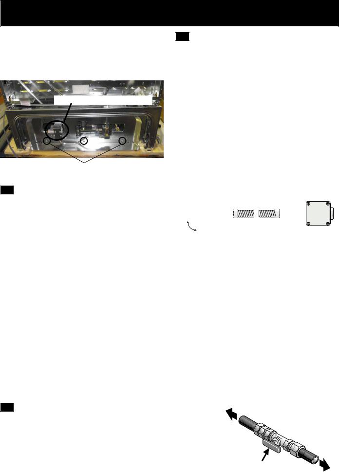
•If you are using a through the floor gas entry, remove the line protector shield from the bottom of the unit to allow access for the pipe line (figure 3).
•We recommend to install a pipe elbow right out of the floor or wall towards the center of the unit to ease the installation.
Gas pressure regulator location
To remove the line protector, remove the 3 |
|
screws. |
Figure 3 |
2. Provide an adequate Gas Supply
When shipped from the factory, this unit is designed to operate on 4" (10,16 cm) water column (1.0 kPa) Natural gas manifold pressure. A convertible pressure regulator is connected to the range manifold and MUST be connected in series with the gas supply line. If LP/Propane conversion kit has been used, follow instructions provided with the kit for converting the pressure regulator to LP/Propane use.
Care must be taken during installation of range not to obstruct the flow of combustion and ventilation air.
For proper operation, the maximum inlet pressure to the regulator should be no more than 14" (35,56 cm) of water column pressure (3,5 kPa). The inlet
pressure to the regulator must be at least 1" (0,25 kPa) greater than the regulator manifold pressure setting.
Examples: If regulator is set for natural gas 4" (10,16 cm) manifold pressure, inlet pressure must be at least 5" (12,7 cm); if regulator has been converted for LP/ Propane gas 10" (25,4 cm) manifold pressure, inlet pressure must be at least 11" (27,9 cm).
Leak testing of the appliance shall be conducted according to the instructions in step 4.
The gas supply line should be ½" or ¾" I.D. (Interior
Diameter)
4. Connect the range to the gas supply
Important: Remove all packing material and literature from range before connecting gas and electrical
supply.
To prevent leaks, put pipe joint sealant on all external pipe threads.
Your regulator is in location as shown in figure 3.
 Do not allow regulator to rotate on pipe when tightening fittings.
Connection to Pressure Regulator
The regulator is already installed on the appliance.
 Do not make the connection too tight. The regulator is die cast. Overtightening may crack the regulator resulting in a gas leak and possible fire or explosion.
Manual |
Flare |
GAS FLOW |
Flare |
Pressure |
|
Shutoff |
|
Regulator |
|||
Union |
|
Union |
|||
Valve |
|
|
|||
|
|
|
|
||
On |
Nipple |
|
Nipple |
|
|
Off |
Flexible |
Access |
|||
|
Connector |
|
|||
|
|
|
Cap |
||
All connections must be wrench-tightened |
|||||
|
|||||
|
|
Figure 4 |
|
|
|
Assemble the flexible connector from the gas supply pipe to the pressure regulator in the following order:
1.manual shutoff valve (not included)
2.1/2" nipple (not included)
3.1/2" flare union adapter (not included)
4.flexible connector (not included)
5.1/2" flare union adapter (not included)
6.1/2" nipple (not included)
7.pressure regulator (included)
Use pipe-joint compound made for use with Natural and LP/Propane gas to seal all gas connections. If flexible connectors are used, be certain connectors are not kinked.
The supply line must be equipped with an approved manual shutoff valve. This valve should be located in the same room as the range and should be in a location that allows ease of opening and closing.
3. Seal the openings
Seal any openings in the wall behind the range and in the floor under the range after gas supply line is installed.
Do not block access to the shutoff valve.
The valve is for turning on or shutting off gas to the appliance.
to appliance
Shutoff Valve -
Open position
to |
|
gas |
suppl |
|
|
|
y |
|
line |
7
30" GAS SLIDE-IN RANGE INSTALLATION INSTRUCTIONS
(Models with Sealed Top Burners)
Once regulator is in place, open the shutoff valve in the gas supply line. Wait a few minutes for gas to move through the gas line.
Check for leaks. After connecting the range to the gas supply, check the system for leaks with a manometer. If a manometer is not available, turn on the gas supply and use a liquid leak detector (or soap and water) at all joints and connections to check for leaks.


 Do not use a flame to check for leaks from gas connections. Checking for leaks with a flame may result in a fire or explosion.
Tighten all connections as necessary to prevent gas leakage in the range or supply line.
Disconnect this range and its individual manual shutoff valve from the gas supply piping system during any pressure testing of that system at test pressures greater than 1/2 psig (3,5 kPa or 14" water column).
Isolate the range from the gas supply piping system by closing its individual manual shutoff valve during any pressure testing of the gas supply piping system at test pressures equal to or less than 1/2 psig (3,5 kPa or 14" water column).
5. LP/Propane Gas Conversion
This appliance can be used with Natural gas or LP/ Propane gas. It is shipped from the factory for use with natural gas.
If you wish to convert your range for use with LP/
Propane gas, use the supplied fixed orifices located in a bag containing the literature marked "FOR LP/PROPANE GAS CONVERSION". Follow the instructions packaged with the orifices for surface, oven and broil burners conversion.
The conversion must be performed by a qualified service technician in accordance with the manufacturer's instructions and all local codes and requirements. Failure to follow these instructions could result in serious injury or property damage.
The qualified agency performing this work assumes responsibility for the conversion.
 Failure to make the appropriate conversion can result in serious personal injury and property damage.
6. Electrical Requirements
120 volt, 60 Hertz, properly grounded dedicated circuit protected by a 15 amp circuit breaker or time delay fuse.
Note: Not recommended to be installed with a Ground Fault Interrupt (GFI).
Do not use an extension cord with this range.
Grounding Instructions
IMPORTANT Please read carefully.
For personal safety, this appliance must be properly grounded.
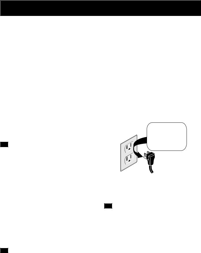
The power cord of this appliance is equipped with a 3-prong (grounding) plug which mates with a standard 3-prong grounding wall receptacle (see Figure 5) to minimize the possibility of electric shock hazard from the appliance.
The wall receptacle and circuit should be checked by a qualified electrician to make sure the receptacle is properly grounded.
Where a standard 2-prong wall receptacle is installed, it is the personal responsibility and obligation of the consumer to have it replaced by a properly grounded 3-prong wall receptacle.
Do not, under any circumstances, cut or remove the third (ground) prong from the power cord.
Preferred Method
Grounding type
wall receptacle Do not, under any circumstances, cut, remove,
or bypass the grounding prong.
Power supply cord with 3-prong grounding plug.
Figure 5
 Disconnect electrical supply cord from wall receptacle before servicing the appliance.
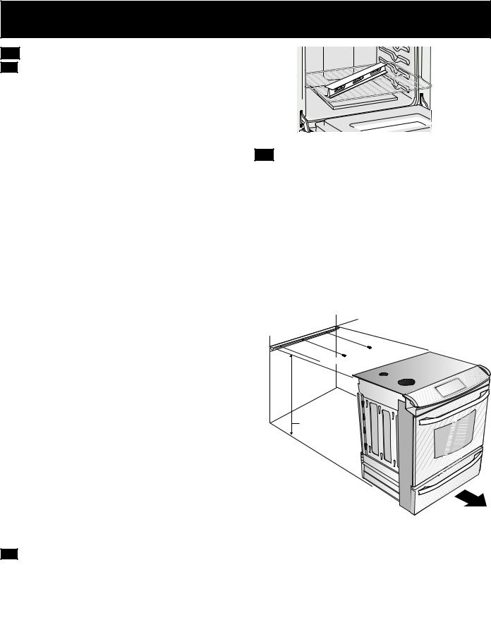
7. Moving the Appliance for Servicing and Cleaning
Turn off the range line fuse or circuit breakers at the main power source, and turn off the manual gas shut-off valve. Make sure the range is cold. Remove
the service drawer (warmer drawer on some models) and open the oven door. Lift the range at the front and slide it out of the cut-out opening without creating undue strain on the flexible gas conduit. Make sure not to pinch the flexible gas conduit at the back of the range when replacing the unit into the cut-out opening. Replace the drawer, close the door and switch on the electrical power and gas to the range.
8
30" GAS SLIDE-IN RANGE INSTALLATION INSTRUCTIONS
(Models with Sealed Top Burners)
8. Range Installation
Important Note: Door removal is not a requirement for installation of the range, but is an added convenience.
Refer to the Use and Care Guide for oven door removal instructions.
Figure 6
Standard Installation
8.1The range cooktop overlaps the countertop at the sides and the range rests on the floor. The cooktop is 31 1/2" (80 cm) wide.
8.2Install base cabinets 30" (76,2 cm) apart. Make sure they are plumb and level before attaching cooktop. Shave raised countertop edge to clear 31 1/2" (80 cm) wide range top rim.
8.3Install cabinet doors 31" (78,7 cm) min. apart so it will not interfere with range door opening.
8.4Cutout countertop exactly as shown on page 4.
For models equipped with Leveling Device:
8.5Make sure the front leveling legs and the rear leveling device are setup higher than the height of the cabinet.
8.6
 Install the anti-tip bracket at this point before placing the range at its final position. Follow the installation instructions on page 12 or 13 or on the anti-tip bracket template supplied with the range.
8.7To provide an optimum installation, the top surface of the countertop must be level and flat (lie on the same plane) around the 3 sides that are adjacent to range cooktop. Proper
adjustments to make the top flat should be made or gaps between the countertop and the range cooktop may occur.
8.8  To reduce the risk of damaging your appliance, do not handle or manipulate it by the cooktop or control console. Manipulate with
8.9Positioncare. range in front of the cabinet opening.
8.10Make sure that the cooktop which overhangs the countertop clears the countertop. If necessary, raise the unit by lowering the leveling legs.
8.11Slide the range into the cutout opening and center it before leveling it.
8.12Level the range (see section 9). The floor where the range is to be installed must be level. Follow the instructions under "Leveling the RangeModels Equipped with Leveling Device".
8.13Adjust leveling legs so that the underside of the cooktop is sitting on the countertop. Carefully screw in (refer to Leveling the range: Models equipped with Leveling Device") the back leveling leg until the cooktop overhang touches slightly the countertop. Then carefully screw in the front two leveling legs until the cooktop overhang touches slightly the countertop.
For models equipped with Leveling Leg only (no leveling device):
8.5Make sure the four leveling legs (front and rear) are setup higher than the height of the cabinet (shown on page 3).
8.6
 Install the anti-tip bracket at this point before placing the range at its final position. Follow the installation instructions on page 12 or 13 or on the anti-tip bracket template supplied with the range.
8.7To provide an optimum installation, the top surface of the countertop must be level and flat (lie on the same plane) around the 3 sides that are adjacent to range cooktop. Proper
adjustments to make the top flat should be made or gaps between the countertop and the range cooktop may occur.
8.8
 To reduce the risk of damaging your appliance, do not handle or manipulate it by the cooktop. Manipulate with care.
8.9Position range in front of the cabinet opening.
8.10Make sure that the cooktop which overhangs the countertop clears the countertop. If necessary, raise the unit by lowering the leveling legs.
8.11Level the range (see section 9). The floor where the range is to be installed must be level. Follow the instructions under "Leveling the RangeModels Equipped with Leveling Legs".
8.12Slide the range into the cutout opening.
IMPORTANT If Accessories Needed
Installation With Backguard
A backguard kit can be ordered through a Service
Center. The cutout depth (21¾" (55,2 cm) Min., 221/8" (56,2 cm) Max.) needs to be increased to 24" (61 cm) when installing a backguard
Installation With End Panel
An end panel kit can be ordered through a Service Center.
Installation With Side Panel
A side panels kit can be ordered through a Service Center. Install cabinet doors 31" (78,7 cm) min. apart so as not to interfere with range door opening.
9
30" GAS SLIDE-IN RANGE INSTALLATION INSTRUCTIONS
(Models with Sealed Top Burners)
9. Leveling the Range
9.1 Models Equipped with Leveling Device
Level the range after installation in the cutout opening.
1.Open the range drawer. The leveling screws control the height of the rear leg.
2.Adjust the appliance legs as follows until the underside of the cooktop (or cooktop glass) surface is sitting level on the countertop (Figure 7).
a.To adjust the front legs, use a wrench on the leg base and turn counterclockwise to lower or clockwise to raise the range.
b.To adjust the rear legs, use a ratchet or a nutdriver and turn the leveling screws
counterclockwise to lower or clockwise to raise the range.
3.Check if the range is level by installing an oven rack in the center of the oven and placing a level on the rack (Figure 8).
4.Take 2 readings with the level placed diagonally in one direction and then the other. Level the range, if necessary, by adjusting the leveling legs.
5.If the range cannot be level, contact a carpenter to correct sagging or sloping floor.
Figure 8
10. Decorative Rear Trim Installation (if required)
1.Disconnect the power from the range.
2.Make sure the range is leveled.
3.Pull range toward you.
4.Measure the distance between the floor and the surface underneath the cooktop frame.
5.Mark that distance on the wall where the decorative trim will be installed.
6.Draw a line.
7.Place the top of the decorative trim under that line.
8.Using the screws provided fix the decorative trim into the wall.
9.Slide the range back into position as far as it will go and reconnect the power source.
 Decorative Trim
 Screw (3)
Distance between the floor and the surface underneath the cooktop frame.
Figure 7
9.2 Models Equipped with Leveling Legs
Level the range and set cooktop height before installation in the cut-out opening.
1.Install an oven rack in the center of the oven.
2.Place a level on the rack (see Figure 8). Take 2 readings with the level placed diagonally in one direction and then the other. Level the range, if necessary, by adjusting the 4 leg levelers with a wrench (see Figure 23).
3.Taking care to not damage the countertop, slide range into cutout opening and double check for levelness.
Figure 9
11. Check Operation
Refer to the Use and Care Guide packaged with the range for operating instructions and for care and cleaning of your range.
Do not touch the burners. They may be hot enough to cause burns.
Remove all packaging from the oven before testing.
11.1 Check Burner Cap Placement
It is very important to be sure that all surface burner caps and burner grates are properly installed and in the correct locations before operating the appliance. Please note that the burner heads are secured to the cooktop. The cooktop is not removable. Do not attempt to remove or lift the cooktop.
10
30" GAS SLIDE-IN RANGE INSTALLATION INSTRUCTIONS
(Models with Sealed Top Burners)


 To prevent flare-ups and avoid creation of harmful by-products, do not use the cooktop without all burner caps properly installed to insure proper ignition and gas flame size.
Always keep the burner caps and burner heads in place whenever the surface burners are in use. DO not allow spills, food, cleaning agents or any other material to enter the gas orifice holder openings.
Check and be sure the size of each burner cap matches the size of the burner head. Check and be sure that all round style burner caps are correctly in place on round burner heads.
Check and be sure that all oval style burner caps are correctly in place on oval burner heads (if equipped). Check and be sure that all dual or twin style burner caps are correctly in place on dual or twin heads (if equipped).
On round style burners, the burner cap lip (Figure 10) should fit snug into the center of burner head and be level. Refer to figures 11 & 12 for correct and incorrect burner cap placement.
Once in place, you may check the fit by gently sliding the burner cap from side to side (Figure 13) to be sure it is centered and firmly seated. When the burner cap lip makes contact inside the center of the burner head you will be able to hear the burner cap click. Please note that the burner cap should NOT move off the center of the burner head when sliding from side to side.
Burner Cap
Burner |
Burner |
Head |
|
|
Cap Lip |
11.3 Check the Igniters
Operation of electric igniters should be checked after range and supply line connectors have been carefully checked for leaks and range has been connected to electric power.
a.To check for proper lighting, push in and turn a surface burner knob to the LITE position. You will hear the igniter sparking.
b.The surface burner should ignite when gas is available to the burner. Purge air from supply lines by leaving knob in the LITE position until burner ignites. Each burner should light within four (4) seconds in normal operation after air has been purged from supply lines.
c.Visually check that burner has a flame, Once the burner ignites, the control knob should be turned out of the LITE position.
d.Try each surface control knob separately until all burner valves have been checked. Each burner location is equipped with a separate electrode.
11.4Adjust the "LOW" Setting of Surface
Burner Valves (linear flow)
Test to verify if LOW setting should be adjusted:
a.Push in and turn control to LITE until burner ignites.
b.Push in and quickly turn knob to lowest position.
c.If burner goes out, reset control to OFF.
d.Remove the surface burner control knob.
For all burner styles (except Dual and Bridge burner)
e.Insert a thin-bladed screwdriver into the hollow valve stem and engage the slotted screw inside. Flame size can be increased or decreased with the turn of screw.
Turn counterclockwise to increase flame size. Turn clockwise to decrease flame size (Figure 14).
Adjust flame until you can quickly turn knob from LITE to lowest position without extinguishing the flame. Flame should be as small as possible without extinguishing.
Fig. 10
Correct Burner Cap |
|
Incorrect Burner Cap |
||||
Placement - Fig. 11 |
|
Placement - Fig. 12 |
||||
|
|
|
|
|
|
|
|
|
|
|
|
|
|
|
|
|
|
|
|
|
|
|
|
|
|
|
|
For Dual and Bridge burner style adjustment only:
e.The inner portion (Simmer) of the dual burner flame size or the rear portion of the bridge burner flame size can be increase or decrease with the turn of screw A.
Use screw B to adjust flame size of the outer portion of the Dual Burner or the center portion of the Bridge Burner (Figure 15). Turn the screw counterclockwise to increase flame size. Turn clockwise to decrease flame size. Adjust flame size until you can quickly turn the knob from LITE to lowest position without extinguishing the flame. Flame should be as small as possible without going out.
Note: Air mixture adjustments are not required on surface burners.
|
Hollow |
|
|
|
Valve |
B |
|
|
Stem |
||
11.2 Turn on Electrical Power and Open |
A |
||
|
|||
|
|
||
Main Shutoff Gas Valve |
Figure 14 |
Figure 15 |
|
|
|
11
30" GAS SLIDE-IN RANGE INSTALLATION INSTRUCTIONS
(Models with Sealed Top Burners)
11.5 Operation of Oven Burners and Oven
Adjustments
11.5.1 Electric Ignition Burners
Operation of electric igniters should be checked after range and supply line connectors have been carefully checked for leaks, and range has been connected to electric power.
The oven burner is equipped with an electric control system as well as an electric oven burner igniter. If your model is equipped with a waist-high broil burner igniter, it will also have an electric burner igniter. These control systems require no adjustment. When the oven is set to
operate, current will flow to the igniter. It will "glow" similar to a light bulb. When the igniter has reached a temperature sufficient to ignite gas, the electrically controlled oven valve will open and flame will appear at the oven burner. There is a time lapse from 30 to 60 seconds after thermostat is turned ON before the flame appears at the oven burner.
When the oven reaches the display setting, the glowing igniter will go off. The burner flame will go "out" in 20 to 30 seconds after igniter goes "OFF". To maintain any given oven temperature, this cycle will continue as long as the display is set to operate.
After removing all packing materials and literature from the oven:
a)Set the oven to BAKE at 300°F. See Use & Care Guide for operating instructions.
b)Within 60 seconds the oven burner should ignite.
Check for proper flame, and allow the burner to cycle once. Reset controls to off.
c)If your model is equipped with a high-waist broiler, set oven to broil. See Use & Care Guide for operating instructions.
d)Within 60 seconds the broil burner should ignite.
Check for proper flame. Reset controls to off.
Lower |
Waist-High Burner |
|
Air Shutter |
||
Oven Baffle |
||
|
||
(removable) |
|
|
|
Lower Oven Bottom |
|
Figure 16 |
Air Shutter (removable) |
|
|
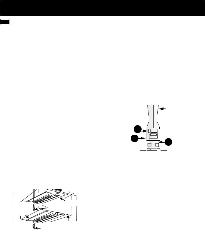
11.5.2 Air Shutter-Oven Burner
The approximate oven burner flame length is 1 inch (distinct inner cone of blue flame).
To determine if the oven burner flame is proper, remove the oven bottom and burner baffle and set the oven to bake at 300°F.
To remove the oven bottom, remove oven hold down screws at rear of oven bottom. Pull up at rear, disengage front of oven bottom from oven front frame, and pull the
oven bottom out of the oven. Remove burner baffle so that burner flame can be observed.
If the flame is yellow, increase air shutter opening size (see "2" in Figure 17). If the entire flame is blue, reduce the air shutter opening size.
To adjust frame loosen lock screw (see "3" in Figure 17), reposition air shutter, and tighten lock screw. Replace oven bottom.
11.5.3 Air Shutter-Broil Burner
The approximate flame length of the burner is 1 inch (distinct inner cone of blue flame). To determine if the broil burner flame is proper, set the oven to broil. If flame is yellow, increase air shutter opening size (see "2" in Figure 17). If the entire flame is blue, reduce the air shutter opening size. To adjust, loosen lock screw (see
"3" in Figure 17), reposition air shutter, and tighten lock |
|
screw. |
Oven Burner Tube |
|
|
Lock Screw 3 |
|
Air Shutter 2 |
1 Orifice Hood |
|
|
Figure 17
When All Hookups are Complete
Make sure all controls are left in the OFF position.
Make sure the flow of combustion and ventilation air to the range is unobstructed.
Model and Serial Number Location
The serial plate is located on the oven front frame behind the oven door (some models) or on the drawer side frame (some models).
When ordering parts for or making inquiries about your range, always be sure to include the model and serial numbers and a lot number or letter from the serial plate on your range.
Your serial plate also tells you the rating of the burners, the type of fuel and the pressure the range was adjusted for when it left the factory.
Before You Call for Service
Read the Before You Call Checklist and operating instructions in your Use and Care Guide. It may save you time and expense. The list includes common occurrences that are not the result of defective workmanship or materials in this appliance.
Refer to your Use & Care Guide for service phone numbers.
12
30" GAS SLIDE-IN RANGE INSTALLATION INSTRUCTIONS
(Models with Sealed Top Burners)
12. Anti-Tip Brackets Installation
Instructions
12.1 Models Equipped with Leveling Device


 To reduce the risk of tipping of the range, the range must be secured to the floor by properly installed anti-tip bracket and screws packed with the range. These parts are located in the oven. Failure to install the anti-tip bracket will allow the range to tip over if excessive weight is placed on an open door or if a child climbs upon it. Serious injury might result from spilled hot liquids or from the range itself.
Follow the instructions below to install the anti-tip brackets.
If range is ever moved to a different location, the antitip brackets must also be moved and installed with the range.
Tools Required:
Adjustable Wrench Ratchet
Drill & 1/8" (0,32 cm) bit 5/16" (0,8 cm) Nutdriver Level
The anti-tip bracket attaches to the floor at the back of the range to prevent range from tipping. When fastening bracket to the floor, be sure that screws do not penetrate electrical wiring or plumbing. The screws provided will work in either wood or concrete.
1.Draw a center line (CL) on the floor where the range should be installed. Also draw a line on the floor at the range back position if there is no wall.
2.Unfold paper template and place it flat on the floor with the right rear corner positioned exactly on the intersection of the center and back lines you just drew before. (Use the diagram below to locate brackets if template is not available (Figure 18)).
3.Mark on the floor the location of the 4 mounting holes shown on the template. For easier installation, 3/16" (0,48 cm) diameter pilot holes 1/2" (1,27 cm) deep can be drilled into the floor.
4.Remove template and place bracket on floor. Line up holes in bracket with marks on floor and attach with
4 screws provided. Bracket must be secured to solid floor (Figure 19). If attaching to concrete floor, first drill 3/16" (0,48 cm) dia. pilot holes using masonry drill bit.
5.Be sure the 4 leveling legs are at the highest position they can be.
6.Slide range into place making sure structure of the range is trapped by the anti-tip bracket (Figure 19). Lower the range by adjusting the 4 leveling legs until the underside of the cooktop is sitting level on the countertop. Refer to "Leveling the Range" section.
7.After installation, verify that the anti-tip bracket is engaged by grasping the top rear edge of the range and carefully attempt to tilt it forward to make sure range is properly anchored.
|
Anti-Tip Bracket |
|
Range |
|
Floor |
|
Floor Mount |
|
Screws |
(CL = Center line) |
Figure 19 |
Rear of Range
Wall
Figure 18 |
13

30" GAS SLIDE-IN RANGE INSTALLATION INSTRUCTIONS
(Models with Sealed Top Burners)
12.2 Models Equipped with Leveling Legs |

 To reduce the risk of tipping of the range, the range must be secured to the floor by the properly installed anti-tip bracket and screws packed with the range. Failure to install the anti-tip bracket will allow the range to tip over if excessive weight is placed on an open door or if child climbs upon it. Serious injury might result from spilled hot liquids or from the range itself.
If range is ever moved to a different location, the antitip bracket must also be moved and installed with the range.
Instructions are provided for installation in wood or cement floor. When fastening to floor, be sure that screws do not penetrate electrical wiring, gas line or plumbing.
A. Locate the Bracket Using the Template - Locate the bracket position (right or left side) by placing the template symmetrically to the center of the final range position. Mark the location of the screw holes, shown on template. 
Figure 20
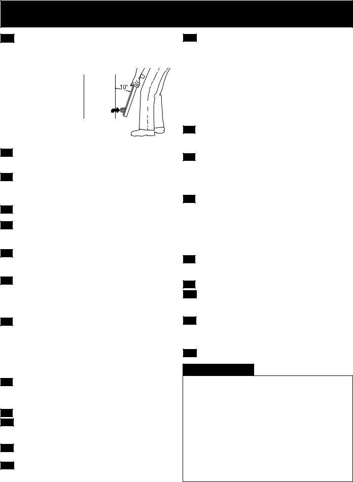
B. Drill Pilot Holes and Fasten Bracket - Drill a 1/8" (0,3 cm) pilot hole where screws are to be located. If bracket is to be mounted to the wall, drill pilot hole at an approximate 20° downward angle. If bracket is to be mounted to masonry or ceramic floors, drill a 3/16" (0,5
cm) pilot hole 1-3/4" (4,4 cm) deep. The screws provided may be used in wood or concrete material. Use a 5/16"
(0,8 cm) nut-driver or flat head screwdriver to secure the bracket in place.
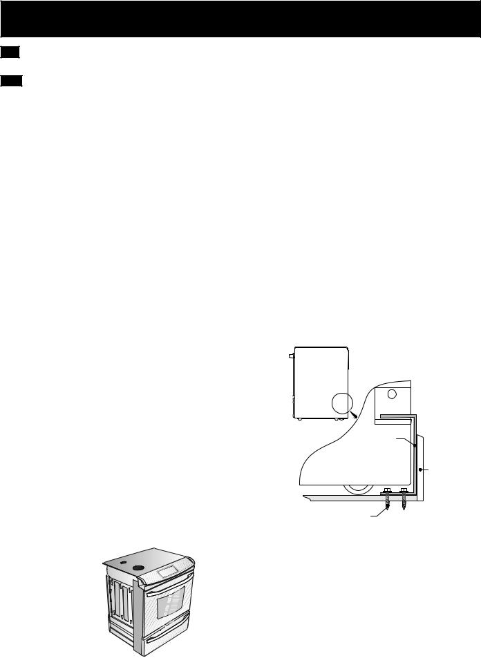
FASTEN BRACKET (WALL OR FLOOR MOUNTING)
Leveling leg
|
Range |
Wall mount |
|
Rearof |
|
|
|
|
|
|
Wall Plate |
Floor Mount |
|
Anti-Tip Bracket |
|
Figure 21 |
|
C. Level and position the range - Slide range to its final position. Insert the range leveling leg in the anti-tip bracket. Visually verify if the anti-tip bracket is engaged. Lower the range by adjusting the 4 leveling legs alternatively until the range is level. Check if the range is level by placing a spirit level on the oven rack. Take 2 readings with the spirit level placed diagonally; take a reading in one direction and then in the other direction. Level the range if necessary by adjusting the leveling legs.
Range side
Figure 22
Leg
Leveler
Raise
Lower 
Figure 23
Figure 24
14
 Loading...