


CFLE3900UW1
TABLE OF CONTENTS
www.frigidaire.com USA 1-800-944-9044 www.frigidaire.ca Canada 1-800-265-8352
All about the
Installation
of your Laundry Center
A11270802 (August 2018)
Important Safety Instructions .....................2
Installation Requirements ..........................4
Unpacking Laundry Center ....................... 13
Installation Instructions ...........................14
Accessories and Replacement Parts ..........20
2
IMPORTANT SAFETY INSTRUCTIONS
WARNING
WARNING indicates a potentially hazardous
situation which, if not avoided, could result
in death or serious injury.
IMPORTANT
IMPORTANT indicates installation, operation
or maintenance information which is
important but not hazard-related.
DANGER
DANGER indicates an imminently hazardous
situation which, if not avoided, will result in
death or serious injury.
CAUTION
CAUTION indicates a potentially hazardous
situation which, if not avoided, may result in
minor or moderate injury.
Denitions
This is the safety alert symbol. It is used to alert you to potential personal injury hazards.
Obey all safety messages that follow this symbol to avoid possible injury or death.
WARNING
For your safety the information in this manual must be followed to minimize the risk of re or
explosion or to prevent property damage, personal injury or loss of life. Save these instructions.
WARNING - RISK OF FIRE
Read all of the following instructions before installing and using this appliance:
• Destroy the carton and plastic bags after the laundry center is unpacked. Children might
use them to play. Cartons covered with rugs, bedspreads, or plastic sheets can become
airtight chambers causing suffocation. Place all materials in a garbage container or make
materials inaccessible to children.
• Laundry center installation and service must be performed by a qualied installer, service
agency or the gas supplier.
• Install the appliance according to the manufacturer’s instructions and local codes.
• The electrical service to the appliance must conform with local codes and ordinances
and the latest edition of the National Electrical Code, ANSI/NFPA 70, or in Canada, the
Canadian Electrical Code CSA C22.1 part 1.
• The gas service to the dryer must conform with local codes and ordinances and the latest
edition of The National Fuel Gas Code ANSI Z223.1/NFPA 54, or in Canada, The Natural
Gas and Propane Installation Code CSA B149.1. An individual manual shut-off valve must
be installed within 6 ft (1.83 m) of the dryer in accordance with the National Fuel Gas
Code, ANSI Z223.1/NFPA 54.
• The laundry center is designed under ANSI Z21.5.1/CSA 7.1 or UL 2158 - CAN/CSA C22.2
No. 112 and UL 2157 - CSA C22.2 No. 169 (latest editions) for HOME USE only. This
laundry center is not recommended for commercial applications such as restaurants, beauty
salons, etc.
• DO NOT install a clothes dryer with exible plastic or exible foil venting
material. Flexible venting materials are known to collapse, be easily crushed
and trap lint. These conditions will obstruct clothes dryer airow and increase
the risk of re.
• The instructions in this manual and all other literature included with this appliance are not
meant to cover every possible condition and situation that may occur. Good safe practice
and caution MUST be applied when installing, operating and maintaining any appliance.
SAVE THESE INSTRUCTIONS FOR FUTURE REFERENCE.
3
IMPORTANT SAFETY INSTRUCTIONS
Shipping Hardware
Foam shipping restraint (inside wash
tub) removed and stored
Foam shipping support (underneath
appliance) removed and stored
Leveling
Laundry center is level, side-to-side and
front-to-back
Cabinet is setting solid on all corners
Water Supply
Use only new hoses and verify rubber
sealing washers are installed
HOT supply is connected to HOT inlet and
COLD supply is connected to COLD inlet
HOT and COLD water supply turned on
No leaks present at water supply con-
nections or appliance inlet connections
-recheck in 24 hours
Drain
Stand pipe or wall drain height min. 33”
Drain hose secured in place with cable
tie (shipped in drum)
Exhaust Venting
Free-owing, clear of lint buildup
4 inch (102 mm) rigid or semi-rigid
ducting of minimal length and turns
NO foil or plastic venting material
Approved vent hood exhausted to
outdoors
Installation Checklist
For your Safety
• DO NOT store or use gasoline, or other
ammable liquids in the vicinity of this or
any other appliance. Read product labels
for warnings regarding ammability and
other hazards.
• DO NOT operate the appliance in the
presence of explosive fumes.
• Remove all staples from the carton.
Staples can cause severe cuts, and also
destroy nishes if they come in contact
with other appliances or furniture.
Gas Supply (Gas Dryer)
Manual shutoff valve present in supply
All connections sealed with approved
sealer and wrench tight
Conversion kit for LP system
Gas supply turned on
No leaks present at all connections -
check with soapy water, NEVER check
with ame
240v Electric Supply
(Electric Dryer)
Approved NEMA 10-30R or 14-30R
service cord with all screws tight on
terminal block
Approved strain relief installed
Terminal access cover installed before
initial operation
Electrical Power
House power turned on
Laundry Center plugged in
Final Checks
Installation Instructions and Use and
Care Guide read thoroughly
Water enters drum when cycle starts
with lid lowered. Dryer door latches and
drum tumbles when cycle starts.
Registration card sent in
Child Safety
Destroy or recycle the carton, plastic bags, and
any exterior wrapping material immediately
after the appliance is unpacked. Children
should never use these items for play. Cartons
covered with rugs, bedspreads, plastic sheets
or stretch wrap may become airtight chambers,
and can quickly cause suffocation.
CAUTION
EXCESSIVE WEIGHT HAZARD
To avoid back or other injury, have more
than one person move or lift the appliance.
WARNING
ELECTRIC SHOCK HAZARD
Certain internal parts are intentionally not
grounded and may present a risk of electrical
shock if contacted during installation. Do
not contact the following parts while the
appliance is energized:
• Pump
• Drive Motor
• Electronic control boards
• Water valve
NOTE
Hoses are not included with washer purchase.
See “Accessories” section for various inlet hose
kits to t your specic installation.
NOTE
Because of potentially inconsistent voltage
capabilities, the use of this dryer with
power created by gas powered generators,
solar powered generators, wind powered
generators or any other generator other
than the local utility company is not
recommended.
4
INSTALLATION REQUIREMENTS
Electrical requirements for
Laundry Center with electric
dryer
CIRCUIT - Individual 30 amp. branch circuit
fused with 30 amp. time delay fuses or circuit
breakers.
POWER SUPPLY - 3-wire or 4-wire, 240 volt,
single phase, 60 Hz, Alternating Current.
The dryer MUST employ a 3-conductor power
supply cord NEMA 10-30 type SRDT rated at
240 volt AC minimum, 30 amp, with 3 open
end spade lug connectors with upturned ends
3-WIRE POWER SUPPLY CORD KIT
(not supplied)
3-wire receptacle
(NEMA type 10-30R)
Pre-Installation Requirements
Tools and materials needed for installation:
• Adjustable pliers
• Phillips, straight, & square bit
screwdrivers
• Adjustable wrench
• Pipe wrench for gas supply (gas dryer)
• LP-resistant thread tape (for natural gas
or LP supply, gas dryer)
• Carpenter’s level
• External vent hood
• 4-inch (102 mm), rigid metal or semi-
rigid metal exhaust duct work
• 3-wire or 4-wire 240 volt cord kit
(electric dryer)
• 4 in. (102 mm) clamp
• Gas line shutoff valve (gas dryer)
• ½ NPT union are adapters (x2) and
exible gas supply line (gas dryer)
• Metal foil tape (not duct tape)
• Inlet hoses (x2)
IMPORTANT
This laundry center is internally grounded to
neutral unless it was manufactured for sale
in Canada.
Only a 4-conductor cord shall be used when
the appliance is installed in a location where
grounding through the neutral conductor is
prohibited. Grounding through the neutral link
is prohibited for: (1) new branch circuit instal-
lations, (2) mobile homes, (3) recreational
vehicles, and (4) areas where local codes DO
NOT permit grounding through the neutral.
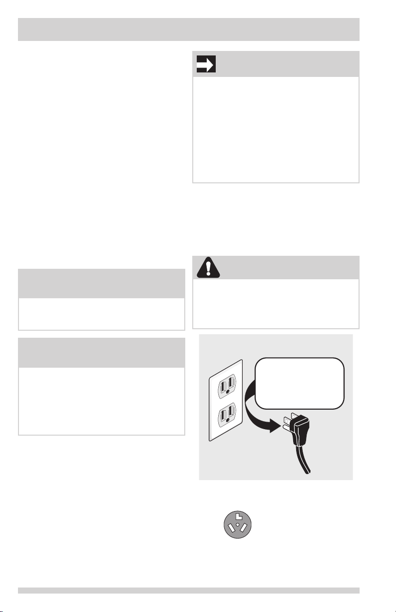
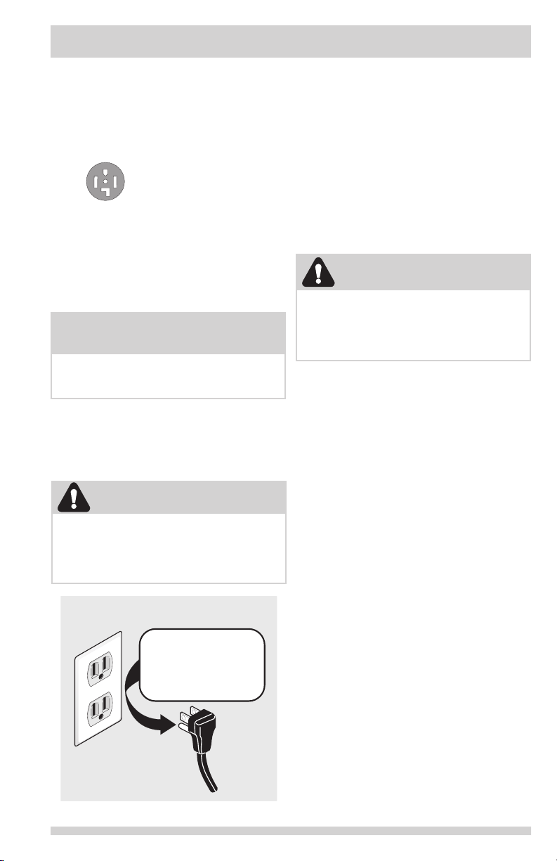
Grounding type wall receptacle
Power cord with
3-prong grounded plug
Do not, under
any circumstances,
cut, remove,
or bypass the
grounding prong.
WARNING
Improper grounding of the laundry center
may cause serious injury or death. Check
with a licensed electrician if you are in doubt
as to whether the appliance is properly
grounded.
OUTLET RECEPTACLE - NEMA 10-30R or NEMA
14-30R receptacle to be located so the power
supply cord is accessible when the dryer is in
the installed position.
GROUNDING CONNECTION - See “Grounding
requirements” in Electrical Installation section.
NOTE
Laundry centers manufactured for sale in
Canada have factory-installed, 4-wire power
supply cord (NEMA 14-30R).
5
INSTALLATION REQUIREMENTS
The dryer MUST employ a 4-conductor power
supply cord NEMA 14-30 type SRDT or DRT
(as required) rated at 240 volt AC minimum,
30 amp, with 4 open end spade lug connectors
with upturned ends or closed loop connectors
and marked for use with clothes dryers. For
4-wire cord connection instructions see ELEC-
TRICAL CONNECTIONS FOR A 4-WIRE SYSTEM.
4-WIRE POWER SUPPLY CORD KIT
(not supplied)
4-wire receptacle
(NEMA type 14-30R)
Gas supply requirements
Electrical requirements for
Laundry Center with gas dryer
CIRCUIT - Individual, properly polarized and
grounded 15 amp. branch circuit fused with 15
amp. time delay fuse or circuit breaker.
POWER SUPPLY - 2-wire, with ground, 120
volt, single phase, 60 Hz, Alternating Current.
POWER SUPPLY CORD - The dryer is equipped
with a 120 volt 3-wire power cord.
GROUNDING CONNECTION - See “Grounding
requirements” in Electrical Installation section.
1. Installation MUST conform with local codes,
or in the absence of local codes, with the
National Fuel Gas Code, ANSI Z223.1 (lat-
est edition).
2. The gas supply line should be 1/2 inch
(1.27 cm) pipe.
3. If codes allow, exible metal tubing may be
used to connect your dryer to the gas sup-
ply line. The tubing MUST be constructed
of stainless steel or plastic-coated brass.
4. The gas supply line MUST have an indi-
vidual shutoff valve installed in accordance
with the B149.1, Natural Gas and Propane
Installation Code.
5. A 1/8 inch (0.32 cm) N.P.T. plugged tap-
ping, accessible for test gauge connection,
MUST be installed immediately upstream of
the gas supply connection to the dryer.
6. The dryer MUST be disconnected from
the gas supply piping system during any
pressure testing of the gas supply piping
system at test pressures in excess of 1/2
psig (3.45 kPa).
7. The dryer MUST be isolated from the gas
supply piping system during any pressure
testing of the gas supply piping system at
test pressures equal to or less than 1/2
psig (3.45 kPa).
8. Connections for the gas supply must com-
ply with the Standard for Connectors for
Gas Appliances, ANSI Z21.24 - CSA 6.10.
WARNING
EXPLOSION HAZARD
Uncoated copper tubing will corrode when
subjected to natural gas, causing gas leaks.
Use ONLY black iron, stainless steel, or
plastic-coated brass piping for gas supply.
WARNING
Improper grounding of the laundry center.
may cause serious injury or death. Check
with a licensed electrician if you are in doubt
as to whether the appliance is properly
grounded.
or closed loop connectors and marked for use
with clothes dryers. For 3-wire cord connection
instructions see ELECTRICAL CONNECTIONS
FOR A 3-WIRE SYSTEM.
Grounding type wall receptacle
Power cord with
3-prong grounded plug
Do not, under
any circumstances,
cut, remove,
or bypass the
grounding prong.
Drain system requirements
1. Drain capable of eliminating 17 gals
(64.3 L) per minute.
2. A standpipe diameter of 1-1/4 in. (3.18 cm)
minimum.
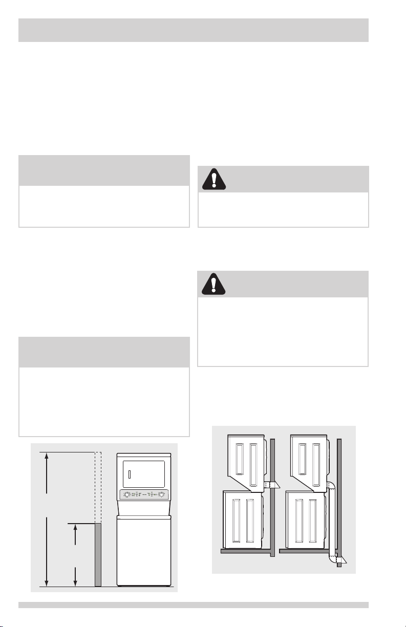
3. Standpipe height above the oor should be:
Minimum height: 33 in. (84 cm)
Maximum height: 96 in. (244 cm)
NOTE
Washers connected to water supplies with
lower inlet pressure will experience longer
lling times and may not complete cycles as
quickly.
6
96"
(244cm)
max.
33"
(84cm)
min.
INSTALLATION REQUIREMENTS
Correct
Exhaust system requirements
If your present system is made up of plastic
duct or metal foil duct, replace it with a
rigid or semi-rigid metal duct. Also, ensure
the present duct is free of any lint prior to
installing dryer duct.
The following are specic requirements
for proper and safe operation of your
dryer.
NOTE
For installations requiring a longer drain
hose, have a qualied technician install a
longer drain hose (according to your model
number) available from an authorized parts
distributor. For drain systems in the oor,
install a syphon break kit available from your
local hardware store.
WARNING
FIRE HAZARD
DO NOT install a clothes dryer with exible
plastic or metal foil venting materials.
Flexible venting materials are known to
collapse, be easily crushed and trap lint.
These conditions will obstruct clothes dryer
airow and increase the risk of re.
Use only 4 inch (102 mm) diameter rigid or
exible metal duct and approved vent hood
which has a swing-out damper(s) that open
when the dryer is in operation. When the
dryer stops, the dampers automatically close
to prevent drafts and the entrance of insects
and rodents. To avoid restricting the outlet,
maintain a minimum of 12 inches (30.5 cm)
clearance between the vent hood and the
ground or any other obstruction.
Water supply requirements
Hot and cold water faucets MUST be installed
within 42 inches (107 cm) of your washer’s
water inlet. The faucets MUST be 3/4 inch (1.9
cm) with threading for laundry hose connection.
Water pressure MUST be between 10 psi
(0.69 bars) and 120 psi (8.27 bars). Pressure
difference between hot and cold cannot be
more than 10 psi. Your water department can
advise you of your water pressure.
WARNING
FIRE HAZARD
Failure to follow these instructions can create
excessive drying times and re hazards.
 Loading...