


CFES3025PBA
Frigidaire CFES3025PBA, CPES3085PFA, CPES3085PFB, CPES3085PFC, CPES3085PFE Installation Guide
...
INSTALLATION INSTRUCTIONS
30" ELECTRIC SLIDE-IN RANGE
INSTALLATION AND SERVICE MUST BE PERFORMED BY A QUALIFIED
INSTALLER.
IMPORTANT: SAVE FOR LOCAL ELECTRICAL INSPECTOR'S USE.
READ AND SAVE THESE INSTRUCTIONS FOR FUTURE REFERENCE.
United States
FOR YOUR SAFETY: Do not store or
use gasoline or other ammable vapors and liquids
in the vicinity of this or any other appliance.
Table of Contents
Important Safety Instructions .......................................... 2
Product & Cabinet Dimensions....................................3-4
To Avoid Breakage .......................................................... 5
Serial Plate Location....................................................... 6
Factory Connected Power Supply Cord ......................... 6
Power Supply Cord Kit ................................................... 6
Access to Terminal Block & Grounding Strap ................. 6
Important Notes to the Installer
1. Read all instructions contained in these installation
instructions before installing range.
2. Remove all packing material from the oven and
the drawer compartments before connecting the
electrical supply to the range.
3. Observe all governing codes and ordinances.
4. Be sure to leave these instructions with the
consumer.
Canada
Electrical Connection to the Range ............................. 7-8
Cabinet Construction ................................................... 8-9
Range Installation ......................................................9-10
Leveling the range ........................................................ 10
Check Operation............................................................11
Anti-Tip Brackets Installation ................................... 12-13
Important Note to the Consumer
Keep these instructions with your owner's guide for
future reference.
Printed in United States
P/N 318201632 (1602) Rev.B
English – pages 1-13
Spanish - pages 14-26
Français – pages 27-40
30" ELECTRIC SLIDE-IN RANGE INSTALLATION INSTRUCTIONS
IMPORTANT SAFETY INSTRUCTIONS
This manual contains important safety symbols and instructions. Please pay attention to these symbols and
follow all instructions given.
This symbol will help alert you to situations that may cause serious bodily harm, death or
property damage.
damage.
This symbol will help alert you to situations that may cause bodily injury or property
Cold temperatures can damage the
electronic control. When using the appliance for the
rsttime,orwhentheappliancehasnotbeenused
for an extended period of time, be certain the unit has
been in temperatures above 32°F (0°C) for at least 3
hours before turning on the power to the appliance.
• Be sure your range is installed and grounded
properly by a qualied installer or service
technician.
• This range must be electrically grounded in
accordance with local codes or, in their absence,
with the National Electrical Code ANSI/NFPA No.
70—latest edition in United States or with CSA
Standard C22.1, Canadian Electrical Code, Part 1
in Canada.
• Theinstallationofappliancesdesignedfor
manufactured (mobile) home installation must conform
with Manufactured Home Construction and Safety
Standard, title 24CFR, part 3280 [Formerly the Federal
Standard for Mobile Home Construction and Safety,
title 24, HUD (part 280)] or when such standard
is not applicable, the Standard for Manufactured
Home Installation 1982 (Manufactured Home Sites,
Communities and Setups), ANSI Z225.1/NFPA 501Alatest edition, or with local codes in United States and
with CAN/CSA-Z240 MH in Canada.
• Make sure the wall coverings around the range
can withstand the heat generated by the range.
• Before installing the range in an area covered with
linoleum or any other synthetic oor covering,
make sure the oor covering can withstand heat
at least 90°F (32,2°C) above room temperature
without shrinking, warping or discoloring. Do not
install the range over carpeting unless you place an
insulating pad or sheet of ¼" (0,64 cm) thick plywood
between the range and carpeting.
Never leave children alone or
unattended in the area where an appliance is in
use. As children grow, teach them the proper, safe
use of all appliances. Never leave the oven door open
when the range is unattended.
Stepping, leaning or sitting on the
door or drawer of this range can result in serious
injuries and can also cause damage to the range.
• Do not store items of interest to children in
the cabinets above the range. Children could be
seriously burned climbing on the range to reach items.
• To eliminate the risk of burns or re by reaching
over heated surface units, cabinet storage space
above the surface unit should be avoided. If
cabinet storage is to be provided the risk can be
reduce by installing a range hood that projects
horizontally a minimum of 5 inches beyond the
bottom of the cabinet.
• Do not use the oven as a storage space. This
creates a potentially hazardous situation.
• Never use your range for warming or heating the
room. Prolonged use of the range without adequate
ventilation can be dangerous.
• Do not store or use gasoline or other ammable
vapors and liquids near this or any other
appliance. Explosionsorrescouldresult.
• Reset all controls to the "off" position after using
a programmable timing operation.
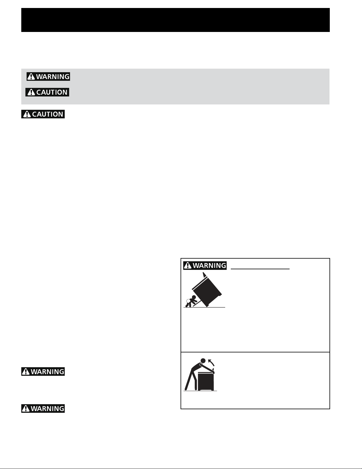
Tip Over Hazard
• A child or adult can tip the range and
be killed.
• Verify the anti-tip device has been
installedtooororwallasper
installation instructions.
• Ensuretheanti-tipdeviceisre-engagedtoooror
wall when the range is moved.
• Do not operate the range without the anti-tip device
in place and engaged.
• Failure to follow these instructions can result in
death or serious burns to children and adults.
To check if the anti-tip bracket is installed
properly, use both arms and grasp
the rear edge of range back. Carefully
attempt to tilt range forward. When
properly installed, the range should not
tilt forward.
Refer to the anti-tip bracket installation instructions
supplied with your range for proper installation.
2
30" ELECTRIC SLIDE-IN RANGE INSTALLATION INSTRUCTIONS
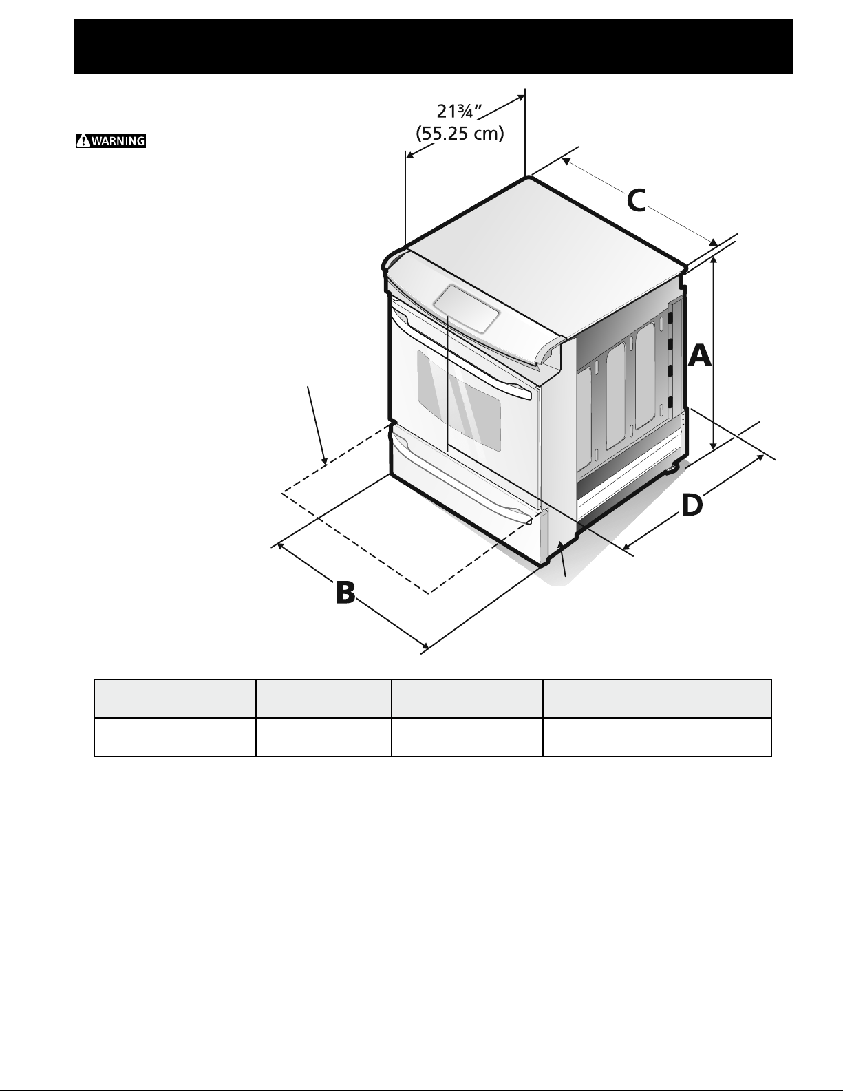
Product Dimensions
Do not
install the unit in the
cabinet before reading
next two pages.
Open Door
(see note 5)
Side Panel
A. HEIGHT
(Under Cooktop)
35 3/4" (90,8 cm)
36 5/8" (93 cm)
B. WIDTH
30" (76,2 cm) 31 1/2" (80 cm) 28 5/16" (71,9 cm)
C. COOKTOP
WIDTH
D. TOTAL DEPTH TO FRONT
OF RANGE
NOTE:
1. Donotpinchthepowersupplycordortheexiblegasconduitbetweentherangeandthewall.
2. Do not seal the range to the side cabinets.
3. 24" (61 cm) minimum clearance between the cooktop and the bottom of the overhead cabinet when
thebottomofwoodormetalcabinetisprotectedbynotlessthan¼"(0,64cm)ameretardant
millboard covered with not less than No. 28 MSG sheet metal, 0,015" (0,4 mm) stainless steel, 0,024"
(0,6 mm) aluminum, or 0,020" (0,5 mm) copper.
30" (76,2 cm) minimum clearance when the cabinet is unprotected.
4. For cutouts below 22 7/8" (58,1 cm), appliance will slightly show out of the cabinet.
5. Allow at least 19 ¼" (48,9 cm) clearance for door depth when it is open.
3
30" ELECTRIC SLIDE-IN RANGE INSTALLATION INSTRUCTIONS
G
E
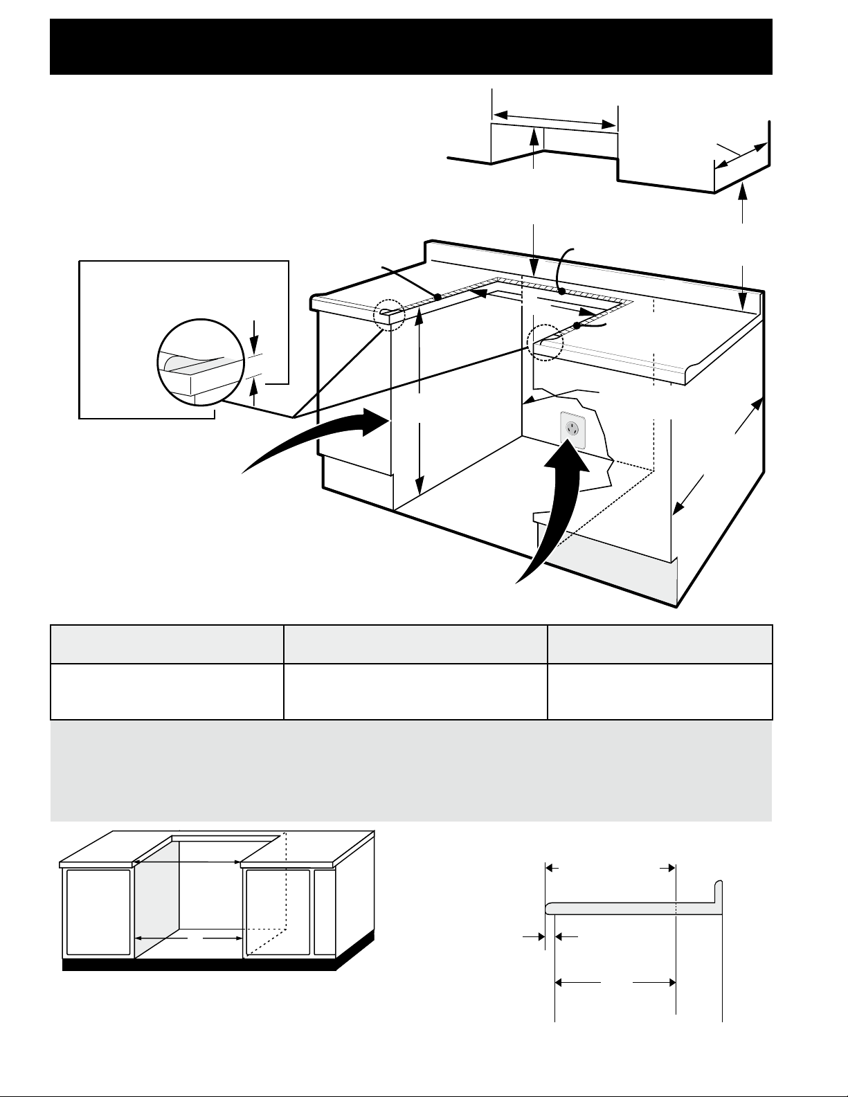
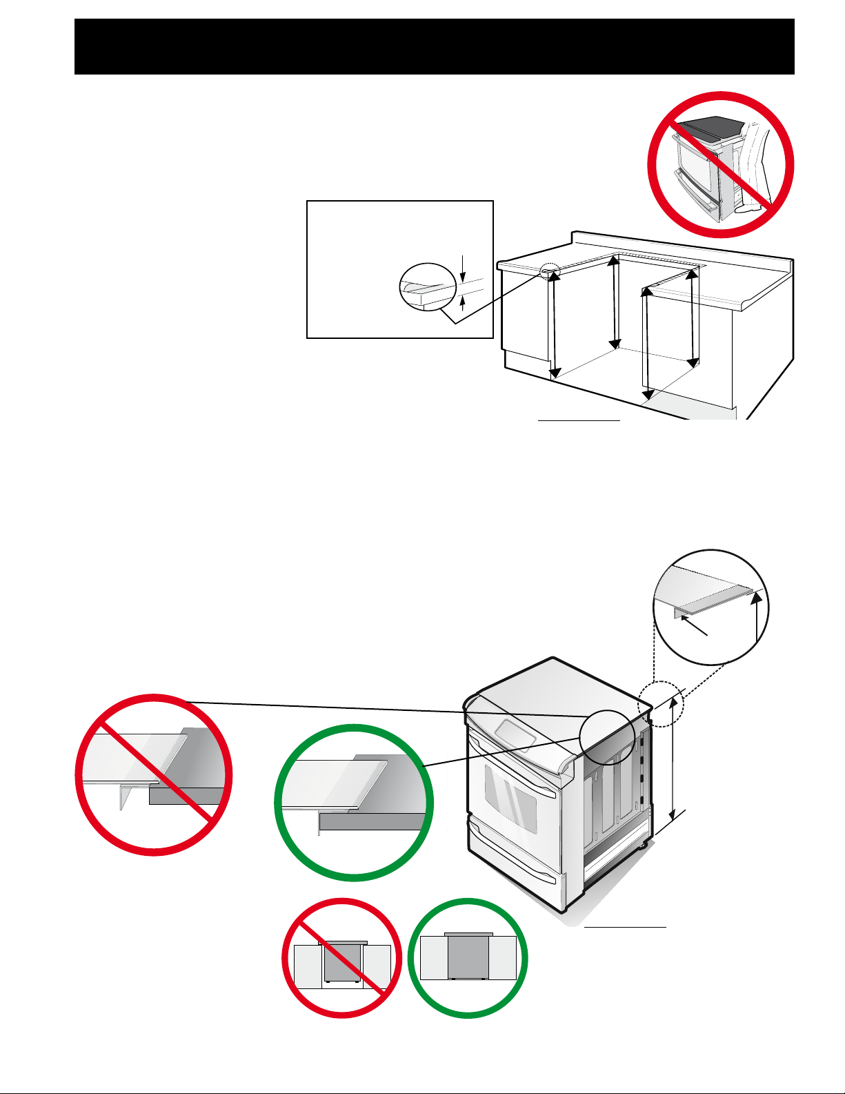
Cabinet Dimensions
Countertop hatched
surfaces should be at
& leveled.
Shave
Raised
Edge To
Clear
Space for
31½" (80
cm) Wide
Cooktop
Rim.
Locate Cabinet Doors 1" (2,5 cm) Min.
From Cutout Opening
1½" Max.
(3,8 cm Max.)
½" Min.
(1,3 cm) Min.
30" Min.
(76,2 cm) Min.
30" Min. (See page 3,
note 3)
(76,2 cm) Min. (See
page 3, note 3)
3/8" Min.
(0,95 cm) Min.
13"
(33 cm)
18" Min.
(45,7 cm) Min.
½" Min.
(1,3 cm) Min.
Approx. 1 7/8"
(4,8 cm)
24" Min.
(61 cm) Min.
Grounded Junction Box or Wall Outlet Should Be
Located 8" to 17" (20,3 - 43,2 cm) From Right Cabinet
and 2" to 4" (5,1-10,2 cm) From Floor
E. CUTOUT WIDTH
(Countertop and cabinet)***
30±1/16"
(76,2±0,16 cm)
F. CUTOUT DEPTH
21 3/4" (55,2 cm) Min.
22 1/8" (56,2 cm) Max
24" (61 cm) Min. with backguard
G. HEIGHT
OF COUNTERTOP
35 7/8" (91,1 cm) Min.
36 5/8" (93 cm) Max.
***IMPORTANT: To avoid cooktop breakage for cutout width (E dimension) of more than 30 1/16"
(76,4 cm), make sure the appliance is centered in the counter opening while pushing into it. Raise
leveling legs and the rear adjustable wheels at a higher position than the cabinet height (see page
5), insert the appliance in the counter and then level. Make sure the unit is supported by the leveling
legs at the front and the wheels at the back and NOT by the cooktop itself.
22 7/8"(58,1 cm) min.
23 1/4"(59,05 cm) max.
E
(see Note 4)
E
IMPORTANT: Cabinet and countertop
width should match the cutout width.
FRONT OF
CABINET
1 1/8"
(2,86 cm)
F
Ref.
4
30" ELECTRIC SLIDE-IN RANGE INSTALLATION INSTRUCTIONS
H1
H2
H3
H4
To avoid breakage: Do NOT handle or manipulate
the unit by the cooktop.
1. Thecounter-toparoundthecut-outshouldbeatandleveled(see
hatched area on illustration 1)
2. Before installing the unit,
measure the heights of
the two (2) cabinet sides
(H1-4), front and back
(see illustration 1) from
theoortothetopofthe
counter.
Shave
Raised
Edge to
Clear Space
for a 31½"
(80 cm) Wide
Cooktop.
1 ½" Max.
(3.8 cm Max.)
3. Level the range using the leveling legs and leveling
device (if equipped) so that the height from the
oortotheundersideofthecooktopglassframeis
Illustration 1
greater than the tallest cabinet measurement by at
least 1/16" (0,16 cm) (see illustration 2).
4. Slide the unit into the cabinet. Make sure the center of the unit is aligned with the center of
the cabinet cut-out.
5. Remove the protective channels on each side of the cooktop (if provided).
6. ThemetalangeundereachsideofthecooktopMUST be placed
over the cabinet countertop for proper unit support. The cooktop
should NOT rest directly on the countertop (see illustration 2) or else
it could cause damage to the cooktop voiding the warranty. Level the
unit if needed.
Metal
Flange
7. After the installation,
MAKE SURE that the
unit is supported by
the leveling legs and
NOT by the cooktop.
To successfully
install the range,
the initial level
heightfromoor
to underside of
cooktop frame
should be at
Illustration 2
5
least 1/16" (0,16
cm) taller than
cabinet sides
as measured in
step 2.
30" ELECTRIC SLIDE-IN RANGE INSTALLATION INSTRUCTIONS
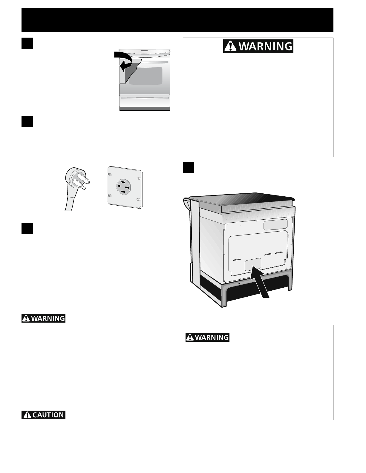
1.
Serial Plate Location
Youwillndthemodelandserial
number printed on the serial plate.
The serial plate is located as
shown.
Remember to record the serial
number for future reference.
Factory Connected Power
2.
Supply Cord (Canada only)
This range is equipped with a factory-connected power
cord (see Figure 1). Cord must be connected to a
grounded 120/240 volt or 120/208 volt range outlet. If
nooutletisavailable,haveoneinstalledbyaqualied
electrician.
Canada Style
Figure 1
Electrical Shock Hazard
• Electrical ground is required on this appliance.
• Do not connect to the electrical supply until
appliance is permanently grounded.
• Disconnect power to the circuit breaker or fuse
box before making the electrical connection.
• This appliance must be connected to a
grounded, metallic, permanent wiring system,
or a grounding connector should be connected
to the grounding terminal or wire lead on the
appliance.
Failure to do any of the above could result in a
re, personal injury or electrical shock.
4.
Access to Terminal Block &
Grounding Strap (U.S.A.)
3.
Power Supply Cord Kit (U.S.A.)
The user is responsible for connecting the power
supply cord to the connection block located behind the
back panel access cover.
This appliance may be connected by means of
permanent"hardwiring";exiblearmoredor
nonmetallic shielded copper cable (when local code
allow it) or by means of a power supply cord kit.
NOTE: Electric Slide-in Range is shipped from factory
with11/8"(2,9cm)dia.holeasshownongure3.Ifa
larger hole is required, punch out the knockout.
Risk of re or electrical shock
exists if an incorrect size range cord kit is used,
the Installation Instructions are not followed, or the
strain relief bracket is discarded.
For mobile homes, new installations or recreational
vehicles, use only a power supply kit designed for a
range at 125V/250V 50A recommended (minimum
40A). Cord must have either 3 (when local code
permits grounding through neutral) or 4 conductors.
Terminal on end of wires must be either closed loop or
open spade lug with upturned ends. Cord must have
strain-relief clamp.
Do not loosen the nuts which
secure the factory-installed range wiring to
terminal block while connecting range. Electrical
failure or loss of electrical connection may occur.
Remove the wire cover here
for access to terminal block
Figure 2
This appliance is manufactured
with the frame grounded by connection of a
grounding strap between the neutral power
supply terminal and the frame. If used in USA,
in a new branch circuit installation (1996 NEC),
mobile home or recreational vehicle, where local
code do not permit grounding through neutral
(white) wire or in Canada; remove the grounding
strap from the frame and cut the other end, near
the neutral terminal. Connect the appliance in
usual manner.
6
30" ELECTRIC SLIDE-IN RANGE INSTALLATION INSTRUCTIONS
5.
Electrical Connection to the
Range (U.S.A.)
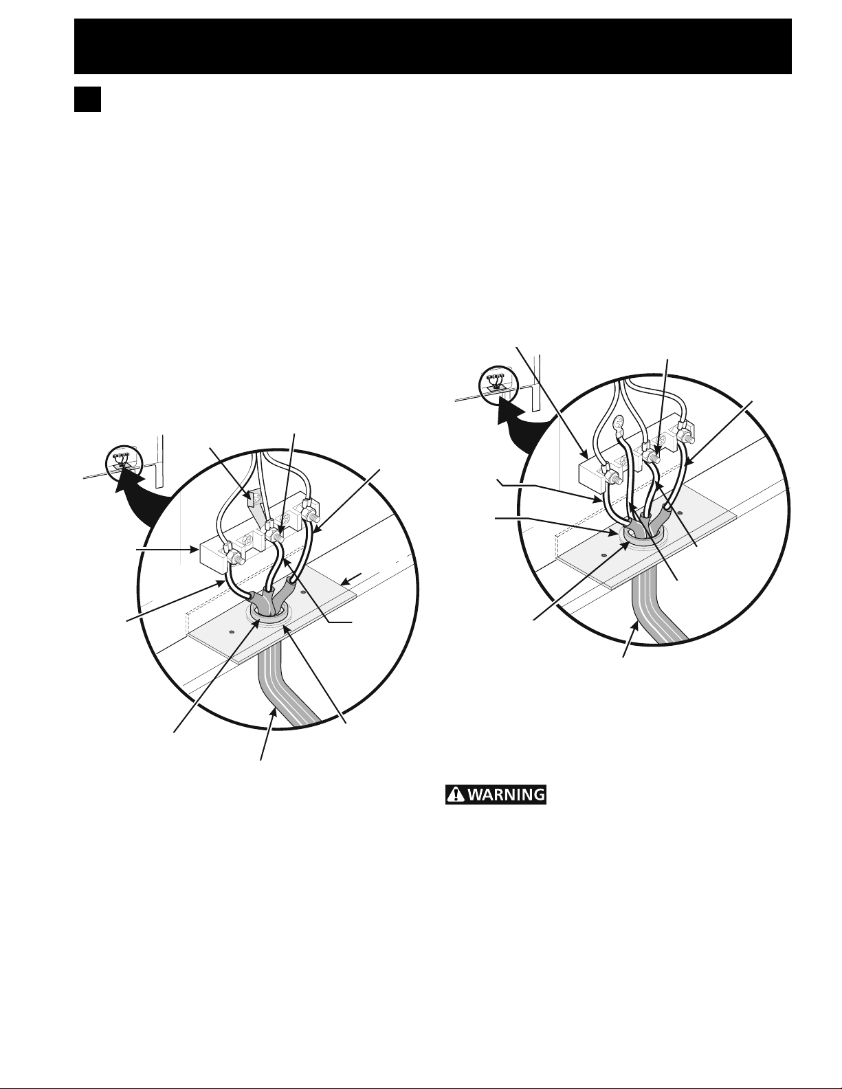
Three Conductor Wire Connection to
Range
If local codes permit connection of the frame grounding
conductor to the neutral wire of the copper power
supply cord (see Figure 3):
1. Remove the screw holding the rear wire cover,
then remove the rear wire cover (access cover)
to expose range terminal connection block (see
Figure 2).
2. Using the nuts supplied in the literature package,
connect the neutral of the copper power supply
cord to the center silver-colored terminal of the
terminal block, and connect the other wires to the
outer terminals. Match wires and terminals by color
(red wires connected to the right terminal, black
wiresconnectedtotheleftterminal)(seegure3).
3. Put back the rear wire cover using the screw
removed on step 1.
Grounding
Strap
Silver Colored Terminal
Red Wire
DO NOT loosen the screws that attach the terminal
block to the appliance.
3. Using the nuts supplied with the literature package,
connect the ground wire (green) of the copper
power supply cord to the frame of the appliance with
the ground screw, using the hole in the frame where
the ground strap was removed (see Figure 4).
4. Connect the neutral of the copper power supply
cord to the center silver-colored terminal of the
terminal block, and connect the other wires to the
outer terminals. Match wires and terminals by color
(red wires connected to the right terminal, black
wires connected to the left terminal).
5. Put back the rear wire cover using the screw
removed on step 1.
Terminal Block
Silver Colored Terminal
Red
Wire
Black Wire
Terminal
Block
Black
Wire
A User Supplied
Strain-relief Must
Be Installed at This
Location.
To 240 V
Receptacle
Figure 3
1 1/8" (2,9 cm) Dia.
Knockout for 1 3/8"
Cord
Mounting
Plate
Neutral
(White Wire)
Direct Connection
Hole. Punch Out
(3,5 cm) Dia. Cord
Kit Hole.
Four Conductor Wire Connection to Range
Where local codes DO NOT permit connection of the
frame grounding conductor to the neutral wire of the
copper power supply cord (see Figure 4):
1. Remove the screw holding the rear wire cover,
then remove the rear wire cover (access cover)
to expose range terminal connection block (see
Figure 2).
2. Remove the grounding strap. Remove the screw
that holds the strap against the appliance. Cut the
strap off at the terminal block, or bend the strap
back and forth to break it from the terminal block.
1 1/8" (2,9
cm) Dia.
Direct
Connection
Hole. Punch
Out Knockout
for 1 3/8" (3,5
cm) Dia. Cord
Kit Hole.
A User Supplied
Strain-relief Must
Be Installed at
This Location
To 240 V
Receptacle
Neutral
(White Wire)
Ground (Bare
Copper Wire)
Figure 4
Direct Electrical Connection to the Circuit
Breaker, Fuse Box or Junction Box
Disconnect power to the circuit breaker
or fuse box before making the electrical connection.
If the appliance is connected directly to the circuit
breaker,fuseboxorjunctionbox,useexible,armored
or nonmetallic sheathed copper cable (with grounding
wire). Supply a U.L. listed strain-relief at each end of
the cable. At the appliance end, the cable goes through
the Direct Connection Hole (see Figure 4) on the Cord
Mounting Plate. Wire sizes (copper wire only) and
connections must conform to the rating of the appliance.
Where local codes permit connecting the
appliance-grounding conductor to the neutral
(white) wire (see Figure 5):
7

30" ELECTRIC SLIDE-IN RANGE INSTALLATION INSTRUCTIONS
1. Be sure that no power is supplied on the cable from
residence.
2. DO NOT remove the grounding strap for 3-wire
installation.
3. In the circuit breaker, fuse box or junction box:
a) Connect the green (or bare copper) wire, the white
appliance cable wire, and the neutral (white) wire
together.
b) Connect the 2 black wires together.
c) Connect the 2 red wires together.
Where local codes DO NOT permit connecting
the appliance-grounding conductor to the neutral
(white) wire, or if connecting to 4-wire electrical
system (see Figure 6):
1. Be sure that no power is supplied on the cable
from residence.
2. Remove the grounding strap from the terminal
block and from the appliance frame.
3. In the circuit breaker, fuse box or junction box:
a) Connect the white appliance cable wire to the
neutral (white) wire.
b) Connect the 2 black wires together.
c) Connect the 2 red wires together.
d) Connect the green (or bare copper) grounding
wire to the grounding wire of the circuit breaker,
fuse box or junction box.
Cable from Residence
Neutral
(white) Wire
Red
Wires
Green
(or Bare Copper)
Wire
Cable from
Appliance
Black
Wires
Junction
Box
White Wire
U.L.-listed Conduit
Connector (or CSA
listed)
Figure 5 - 3-Wire (Grounded Neutral) Electrical
System (Example: Junction Box)
Green (or Bare
Copper) Wire
Red
Wires
Cable from Residence
White Wire
6.
Cabinet Construction
6.1
To eliminate the risk of burns
orrebyreachingoverheatedsurfaceunits,donot
have cabinet storage space above the range. If there
is cabinet storage space above range, reduce risk
by installing a range hood that projects horizontally
a minimum of 5" (12,7 cm) beyond the bottom of the
cabinet.
6.2
Countertop Preparation
• Thecooktopsidesoftherangetoverthecutout
edge of your countertop.
• Ifyouhaveasquare nish (at) countertop, no
countertop preparation is required. Cooktop sides lay
directly on edge of countertop.
• Formed front-edged countertops must have
moldededgeshavedat3/4"(1,9cm)fromeach
front corner of opening (Figure 7).
• Tile countertops may need trim cut back 3/4" (1,9
cm) from each front corner and/or rounded edge
attened(Figure7).
Min.
Cutout
Width
Formed or tile countertop
trimmed ¾" (1,9 cm) back at
front corners of countertop
opening.
Figure 7
• If the existing cutout width is greater than 30
1/16" (76,4 cm), reduce the ¾" (1,9 cm) dimension.
• Countertop must be level. Place a level on the
countertop,rstsidetoside,thenfronttoback.Ifthe
countertop is not level, the range will not be level. The
oven must be level for satisfactory baking results.
Cooktopsidesofrangetoveredgesofcountertop
opening
Green (or Bare
Copper) Wire
Junction
Box
Figure 6 – 4-Wire Electrical System
U.L.-listed Conduit
Cable from
Appliance
Connector (or CSA
listed)
(Example: Junction Box)
Black
Wires
White Wire
8
30" ELECTRIC SLIDE-IN RANGE INSTALLATION INSTRUCTIONS
Floor Mount
Mount
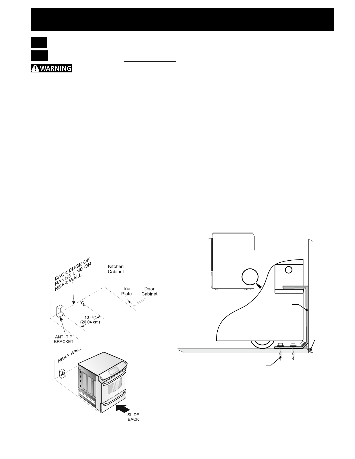
7.
Anti-Tip Brackets Installation
7.1
Models Equipped with Leveling Device
To reduce the risk of tipping of the
range,therangemustbesecuredtotheoorby
properly installed anti-tip bracket and screws packed
with the range. These parts are located in the oven.
Failure to install the anti-tip bracket will allow the range
to tip over if excessive weight is placed on an open door
or if a child climbs upon it. Serious injury might result
from spilled hot liquids or from the range itself.
Follow the instructions below to install the anti-tip
brackets.
If range is ever moved to a different location, the antitip brackets must also be moved and installed with the
range.
Tools Required:
Adjustable Wrench
Ratchet
Drill & 1/8" (0,32 cm) bit
5/16" (0,8 cm) Nutdriver
Level
Theanti-tipbracketattachestotheoor(orbackwall)
at the back of the range to prevent range from tipping.
Whenfasteningbrackettotheoor,besurethatscrews
do not penetrate electrical wiring or plumbing. The
screws provided will work in either wood or concrete.
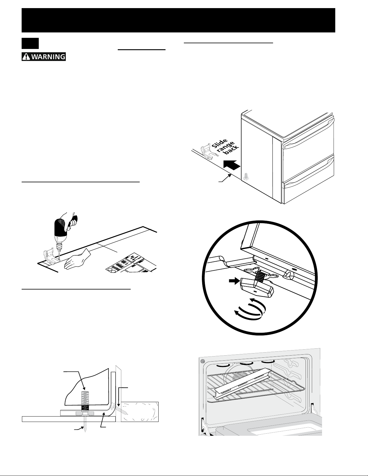
1. Drawacenterline(CL)ontheoorwheretherange
shouldbeinstalled.Alsodrawalineontheoorat
the range back position if there is no wall.
2. Unfoldpapertemplateandplaceitatontheoor
with the right rear corner positioned exactly on the
intersection of the center and back lines you just
drew before. (Use the diagram below to locate
brackets if template is not available. (Figure 8))
3. Markontheoor(orwall)thelocationofthe
mounting holes shown on the template. For easier
installation, 3/16" (0,48 cm) diameter pilot holes 1/2"
(1,27cm)deepcanbedrilledintotheoor(orwall).
4. Removetemplateandplacebracketonoor.Lineup
holesinbracketwithmarksonoor/wallandattach
with screws provided. Bracket must be secured to
solidoororwall(Figure9).Ifattachingtoconcrete
oor,rstdrill3/16"(0,48cm)dia.pilotholesusing
masonry drill bit.
5. Be sure the 4 levelling legs are at the highest
position they can be.
6. Slide range into place making sure structure of the
range is trapped by the anti-tip bracket (Figure 9).
Lower the range by adjusting the levelling legs until
the underside of the cooktop is sitting level on the
countertop. Refer to “Levelling the Range” section.
7. After installation, verify that the anti-tip bracket is
engaged by grasping the top rear edge of the range
and carefully attempt to tilt it forward to make sure
range is properly anchored.
(CL = Center line)
Figure 8
Range
Wall
Anti-Tip Bracket
Wall
Rear of Range
Floor
Figure 9
9
30" ELECTRIC SLIDE-IN RANGE INSTALLATION INSTRUCTIONS
Range side
FASTEN BRACKET
ALL OR FLOOR MOUNTING)
7.2
Models Equipped with Leveling Legs
To reduce the risk of tipping of the
range,therangemustbesecuredtotheoorbythe
properly installed anti-tip bracket and screws packed
with the range. Failure to install the anti-tip bracket will
allow the range to tip over if excessive weight is placed
on an open door or if child climbs upon it. Serious injury
might result from spilled hot liquids or from the range
itself.
If range is ever moved to a different location, the antitip bracket must also be moved and installed with the
range.
Instructions are provided for installation in wood or
cementoor.Whenfasteningtooor,besurethat
screws do not penetrate electrical wiring or plumbing.
A. Locate the Bracket Using the Template - Locate
the bracket position (right or left side) by placing the
templatesymmetricallytothecenterofthenalrange
position. Mark the location of the screw holes, shown on
template.
C. Level and position the range - Slide range to its
nalposition.Inserttherangelevelinglegintheanti-tip
bracket. Visually verify if the anti-tip bracket is engaged.
Lower the range by adjusting the 4 leveling legs
alternatively until the range is level. Check if the range
is level by placing a spirit level on the oven rack. Take
2 readings with the spirit level placed diagonally; take a
reading in one direction and then in the other direction.
Level the range if necessary by adjusting the leveling
legs.
Figure 12
B. Drill Pilot Holes and Fasten Bracket - Drill a 1/8"
(0,3 cm) pilot hole where screws are to be located. If
bracket is to be mounted to the wall, drill pilot hole at
an approximate 20° downward angle. If bracket is to be
mountedtomasonryorceramicoors,drilla3/16"(0,5
cm) pilot hole 1-3/4" (4,4 cm) deep. The screws provided
may be used in wood or concrete material. Use a 5/16"
(0,8cm)nut-driveroratheadscrewdrivertosecurethe
bracket in place.
Leveling leg
Floor Mount
Figure 10
(W
Wall mount
Rear of Range
Wall Plate
Anti-Tip Bracket
Figure 11
Leg
Leveler
Raise
Lower
Figure 13
Figure 14
10

30" ELECTRIC SLIDE-IN RANGE INSTALLATION INSTRUCTIONS
8.
Range
Installation
Important Note:
Door removal is not
a requirement for
installation of the
range, but is an added
convenience. Refer to
the Use and Care Guide
for oven door removal
instructions.
Standard Installation
The range cooktop overlaps the countertop at
8.1
thesidesandtherangerestsontheoor.The
cooktop is 31½" (80 cm) wide.
Install base cabinets 30" (76,2 cm) apart. Make
8.2
sure they are plumb and level before attaching
cooktop. Shave raised countertop edge to clear
31½" (80 cm) wide range top rim.
Install cabinet doors 32" (81,3 cm) min. apart so
8.3
as not to interfere with range door opening.
Cutout countertop exactly as shown on page 4.
8.4
For models equipped with Leveling Device:
Make sure the front leveling legs and the rear
8.5
leveling device are setup higher than the height
of the cabinet.
Install the anti-tip bracket at
8.6
this point before placing the range at its nal
position. Follow the installation instructions
on page 12 or on the anti-tip bracket template
supplied with the range.
To provide an optimum installation, the top
8.7
surface of the countertop must be level and
at(lieonthesameplane)aroundthe3sides
that are adjacent to range cooktop. Proper
adjustmentstomakethetopatshouldbemade
or gaps between the countertop and the range
cooktop may occur.
To reduce the risk of damaging
8.8
your appliance, do not handle or manipulate it by the
ceramic glass. Manipulate with care.
8.9
Position range in front of the cabinet opening.
Make sure the cooktop glass that overhangs the
8.10
countertop clears the countertop before sliding
range into position. If necessary, raise the unit by
lowering the leveling legs.
Slide the range into the cutout opening and
8.11
center it before leveling it.
8.12
Level the range (see section 9). Theoor
where the range is to be installed must be level.
Follow the instructions under "Leveling the
Figure 15
Range- Models Equipped with Leveling Device".
On models with a leveling device, remove the
8.13
rear legs and discard. Adjust the leveling legs
on the front of the appliance so that the cooktop
glass clears the countertop. Level the appliance
(see Leveling the range: Models Equipped
with Leveling Device). The glass should not be
supported by the countertop or any hatched or
shaved areas of the countertop.
For models equipped with Leveling Leg only (no
leveling device):
Make sure the four leveling legs (front and rear)
8.5
are setup higher than the height of the cabinet.
8.6
Install the anti-tip bracket at
this point before placing the range at its nal
position. Follow the installation instructions
on page 13 or on the anti-tip bracket template
supplied with the range.
To provide an optimum installation, the top
8.7
surface of the countertop must be level and
at(lieonthesameplane)aroundthe3sides
that are adjacent to range cooktop. Proper
adjustmentstomakethetopatshouldbemade
or gaps between the countertop and the range
cooktop may occur.
To reduce the risk of damaging
8.8
your appliance, do not handle or manipulate it
by the ceramic glass. Manipulate with care.
Position range in front of the cabinet opening.
8.9
Make sure that the glass which overhangs the
8.10
countertop clears the countertop. If necessary,
raise the unit by lowering the leveling legs.
Level the range(seesection9).Theoor
8.11
where the range is to be installed must be level.
Follow the instructions under "Leveling the
Range-Models Equipped with Leveling Legs".
8.12
Slide the range into the cutout opening.
IMPORTANT
Installation With Backguard
The cutout depth of (21 3/4" (55,2 cm) Min., 22 1/8"
(56,2 cm) Max.) needs to be increased to 24" (61
cm) when installing a backguard.
Installation With End Panel
A End Panel kit can be ordered through a Service
Center.
Installation With Side Panels
A Side Panels kit can be ordered through a Service
Center. Note: Install cabinet doors 32" (81,3 cm) min.
apart so as not to interfere with range door opening.
If Accessories Needed :
11
30" ELECTRIC SLIDE-IN RANGE INSTALLATION INSTRUCTIONS
9.
Leveling the range
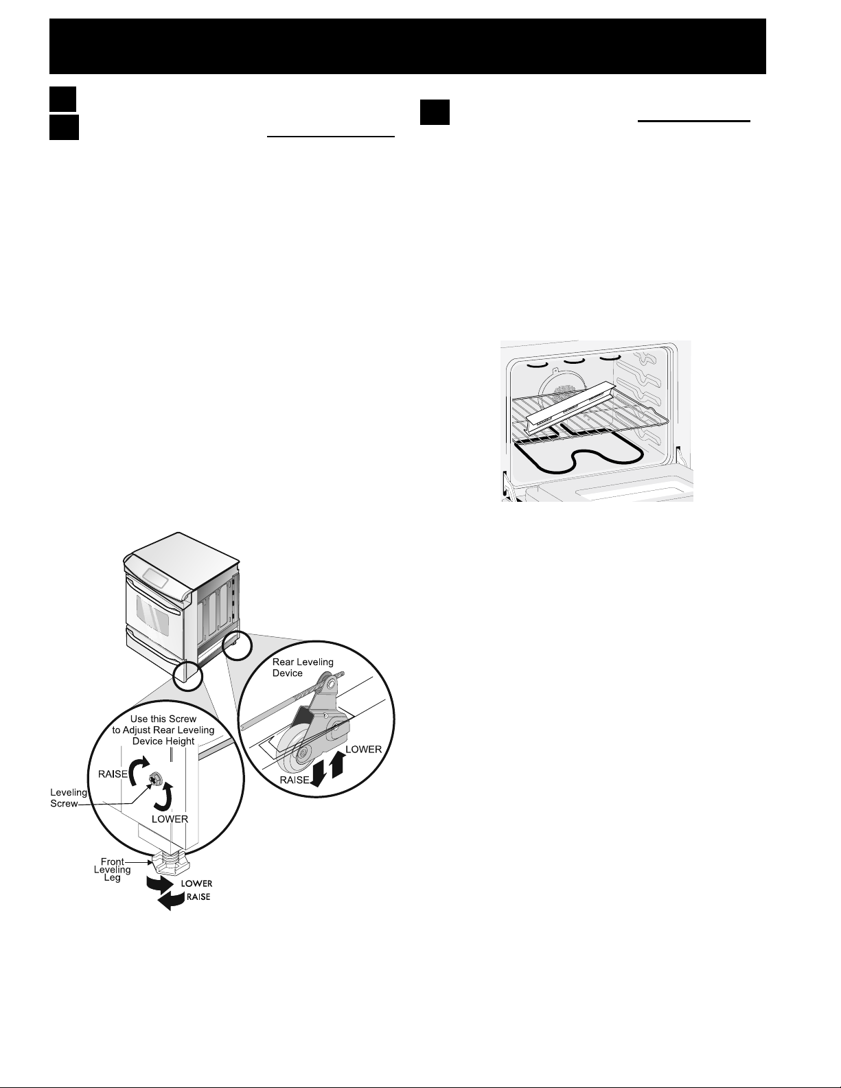
9.1
Models Equipped with Leveling Device
Level the range after installation in the cutout
opening.
1. Open the range drawer. The leveling screws control
the height of the rear wheels.
2. Adjust the appliance wheels and legs as follows
until the underside of the cooktop surface is sitting
level on the countertop (Figure 16).
a. To adjust the front legs, use a wrench on
the leg base and turn clockwise to lower or
counterclockwise to raise.
b. To adjust the rear wheels, use a ratchet
or a nutdriver and turn the leveling screws
counterclockwise to lower or clockwise to raise.
3. Check if the range is level by installing an oven rack
in the center of the oven and placing a level on the
rack (Figure 17).
4. Take 2 readings with the level placed diagonally in
one direction and then the other. Level the range,
if necessary, by adjusting the leveling legs and
wheels.
5. If the range cannot be level, contact a carpenter to
correctsaggingorslopingoor.
9.2
Models Equipped with Leveling Legs
Level the range and set cooktop height before
installation in the cut-out opening.
1. Install an oven rack in the center of the oven.
2. Place a level on the rack (see Figure 17). Take 2
readings with the level placed diagonally in one
direction and then the other. Level the range, if
necessary, by adjusting the 4 leg levelers with a
wrench (see Figure 13).
3. Taking care to not damage the countertop, slide
range into cutout opening and double check for
levelness.
Figure 17
Figure 16
12
 Loading...