


CFEB30S5DB2
Frigidaire CFEB30S5DB2, CFEB30S5DB4, CFEB30S5DB6, CFEB30S5DB7, CFEB30S5DB8 Installation Guide
...
INSTALLATION AND SERVICE MUST BE PERFORMED BY A QUAUFIED INSTALLER.
IMPORTANT: SAVE FOR LOCAL ELECTRICAL INSPECTOR'S USE.
READ AND SAVE THESE INSTRUCTIONS FOR FUTURE REFERENCE.
FOR YOUR SAFETY: Do not store or use gasoline or other flammable vapors and liquids in
the vicinity of this or any other appliance.
Your new wa[[ oven has been designed to fit a Jim[ted variety of cutout sizes to make the job of installing
easier, The first step of your installation should be to measure your current cutout dimensions and
compare them to the cutout dimensions chart below for your mode[, You may find little or no cabinet
work being necessary,
Do not remove spacers (if equipped) on the side walls and/or on the back of the bui[t4n
oven, These spacers center the oven in the space provided. The oven must be centered to prevent
excess heat buildup that may result in heat damage or fire,
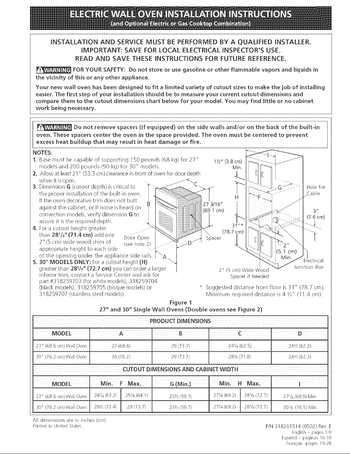
1. Base must be capable of supporting 150 pounds (68 kg) for 27" 1Y2" (3.8 cm)[__
models and 200 pounds (90 kg) for 30" models. Min i
NOTES: __
2. Allow at least21 " (53.3 cm)clearancein front of oven for door depth _.
when it isopen.
the proper installation of the builtqn oven _-.__"_--_ ..... jCab e
If the oven decoratwe trim does not butt B " ' [
aga nst the cab net or fnose sheardon 3/16 [ [
- . ' . . . kb_._cm_ l #-_ 3"
convection models, verify dimension G to _ _ _ ........ _ _ _
. . " H i F...._ '
assure t sthe requ reddepth .. l "'[ _ (_": _=-_- _"_ _'''1
4. For a cutout height greater ......"__ <I ..... [_ _ _ _
.... _, _ / bpacer l _ [
2 (5cm)wldewoodshlmof (seenote2) ..... '" _f _D/ -_i _ [_ "_"_2" _
appropriate height to each side .....".... "--q>._ .... \
of the opening under the appliance side rails A "_ "' -]
,, - • M_n. Electrical
5. 30 MODELS ONLY: Fora cutout height (H) _ __n<
- - ,-.... kb./ cm2
greater than 28sA'' (72.7 cm) you can order a larger 2" (5 cm) Wide Wood _ Junction Box
inferior trim, contact a Service Center and ask for Spacer if Needed
part #318259703 (for white models), 318259704
(black models), 318259705 (bisque models) or * Suggested distance from floor is 31" (78.7 cm).
318259707 (stainlesssteel models). Minimum required distance is 4 Y2" (I 1.4 cm).
Figure 1
27" and 30" Single Wall Ovens (Double ovens see Figure 2)
PRODUCT DIMENSIONS
27" (686 cm)Wall Oven 27 (686)
30" (762 crn) Wall Oven 30 (762)
29 (737)
29 (737)
24sis (625) 24K, (622)
28¼ (71 8) 2@/2 (622)
MODEL Mira F Maxl' G(Min.} " Mira H Max.
27" (686 crn) Wall Oven 247s (632) 2%A (64.1) 23Y2 (597) 27Y4 (69.2) 28s/s (72.7)
30" (762 cm) Wall Oven 28Y_ (724) 29 (737) 23V2 (597) 271_ (69.2) 28s/s (72.7)
All dimensions are in inches (cm)
Printedin United States
i
27Vs (689) Min
30Vs (76.5) Min
P/N 318201514 (0502) Rev E
English - pages 1-9
Espai_o[ - p_ginas 10-18
Francais-pages 19-28
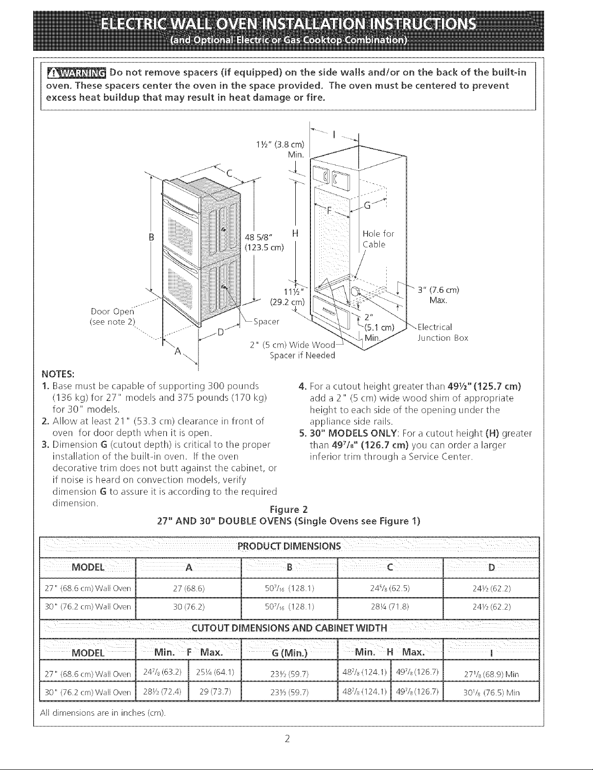
Do not remove spacers (if equipped) on the side wails and/or on the back of the built-in
oven, These spacers center the oven in the space provided, The oven must be centered to prevent
excess heat buildup that may result in heat damage or fire,
3" (7.6 cm)
Max,
2" (5 cm)Wide Wood
-. Spacerif Needed
NOTES:
1. Base must be capable of supporting 300 pounds
(136 kg) for 27" models and 375 pounds (170 kg)
for 30" models.
2. Allow at least 21 " (53.3 cm) clearance in front of
oven for door depth when it is open.
3. Dimension G (cutout depth) is critical to the proper
installation of the built-in oven. If the oven
decorative trim does not butt against the cabinet, or
if noise is heard on convection models, verify
dimension G to assure it is according to the required
dimension. Figure 2
27" AND 30" DOUBLE OVENS (Single Ovens see Figure 1)
27" (68 6 era)Wail Oven 27 (68.6) 1 507//6 (128.1) [ 24s/s (62.5) [ 24Y2 (62.2)
4. For a cutout height greater than 491/:,'' (!25.7 cm)
add a 2" (5 cm) wide wood shim of appropriate
height to ea(h side of the opening under the
appliance side rails.
5. 30" MODELS ONLY: Fora cutout height (H) greater
than 49Ud' (126.7 cm) you can order a larger
inferior trim through a Service Center.
Junction Box
3o"<762crNWa,Oven :30<76.2> _ SOTS6<12s.1> 2s_<71s> _ 24v_<62.2>
CUTOUT DIMENSIONS AND CABINET WIDTH
MODEL Max: GiM,n. J....Min: ]
30" (76 2 cm)Wail Oven J 281/,' (72.4) 29 (73.7) I 231/2(59 7) [ 48Vs (124.1)49Vs (126 7) I 30Vs (76.5) Mir_
A[[ dimensions are in inches (cm),
Important Notes to the [nstammer
1. Read all instructions contained in these installation
instructions before installing the wall oven.
2. Remove all packing material from the oven
compartments before connecting the electrical supply
to the wall oven.
3. Observe all governing codes and ordinances.
4. Be sure to leavethese instructions with the consumer.
5. Oven door may be removed to facilitate installation.
6. THESE OVENS ARE NOT APPROVED FOR
STACKABLE OR S[DE-BY-S[DE [NSTALLAT[ON.
Important Note to the Consumer
Keep these instructions with your Owner's Guide for future
reference.
IMPORTANT SAFETY
[NSTRU S
Be sure your wall oven is installed and grounded
properJy by a qualified installer or service
technician.
• This wall oven must be eIectrka[Iy grounded in
accordance with iota[ codes or, in their absence,
with the Nationa[ EJectrica[ Code ANSJ/NFPA
No.70- tatest edition in United Sates, or with CSA
Standard C22.1, Canadian Electrical Code, Part 1, in
Canada.
Stepping, [eaning or sitting on the
door of this wall oven can resu[t in serious injuries
and can also cause damage to the wait oven.
Never use your wail oven for warming or heating
the room. Prolonged use of the wall oven without
adequate ventilation can be dangerous.
2. Electrical Requirements
This appliance must be supplied with the proper voltage
and frequency, and connected to an individual, properly
grounded branch circuit, protected by a circuit breaker or
fuse, having amperage as noted on the rating plate (the
rating plate is located on the side trim).
Observe all governing codes and local ordinances
1. A 3-wire or 4-wire single phase 120/240 or 120/208
Volt, 60 Hz AC only electrical supply is required on
a separate circuit fused on both sides of the line
(time-delay fuse or circuit breaker is recommended).
DO NOT fuse neutral. The fuse size must not exceed
the circuit rating of the appliance specified on the
nameplate. Only certain cooktop models may be
installed over certain builtqn electric oven models.
Approved cooktops and builtqn ovens are listed by
the MFG ID number (see the insert sheet included in
the literature package).
2. The single wall oven can consume up to 4000W at
240Vac; use a circuit breaker of 30 Amp with wire
gauge #8 AWG. The double wall oven can consume
up to 8000W at 240Vac; use a circuit breaker of 40
Amp with wire gauge #8 AWG.
NOTE: Wire sizes and connections must conform with
the fuse size and rating of the appliance in accordance
with the American National Electrical Code ANSI/NFPA
No. 70qatest edition, or with Canadian CSA Standard
C22.1, Canadian Electrical Code, Part 1, and local codes
and ordinances.
An extension cord should not be used
with this appliance. Such use may result in a fire,
electrical shock, or other persona[ injury. If you need
a longer power cord you can order for purchase a 10'
(3m) power cord kit #903056-9010 by calling the Service
Center.
The electrical power to the oven must
be shut off while Hne connections are being made.
Failure to do so could result [n serious injury or
death.
1. Carpentry
Refer to figure I or 2 for the dimensions applicable to
your appliance, and the space necessary to receive the
oven. The oven support surface may be solid plywood or
similar material, however the surface must be level from
side to side and from front to rear.
3. These appliances should be connected to the fused
disconnect (or circuit breaker) box through flexible
armored or nonmetallic: sheathed cable. The flexible
armored cable extending from the appliance should
be connected directly to the junction box. The
junction box should be located asshown in Figure 1
or Figure 2 and with as much slack as possible
remaining in the cable between the box and the
appliance, so it can be moved if servicing is ever
necessary.
4. A suitable strain relief must be provided to attach
the flexible armored cable to the junction box.
Electrical Shock Hazard
• E[ectrka[ ground [s required on this app!iance,
• Do not connect to the electrical supply until
appliance is permanently grounded,
• Disconnect power to the junction box before
making the eJectrkaJ connection,
• This appliance must be connected to a
grounded, metallic, permanent wiring system,
or a grounding connector should be connected
to the grounding terminal or wire lead on the
appliance.
• Do not use a gas supply line for grounding the
appliance.
Failure to do any of the above could result in a
fire, personal injury or electrical shock,
In cold weather shipping and storage
conditions, make sure that oven is in final location at
least three (3) hours before switching on power.
Switching on power while oven is still cold may damage
the oven controls.
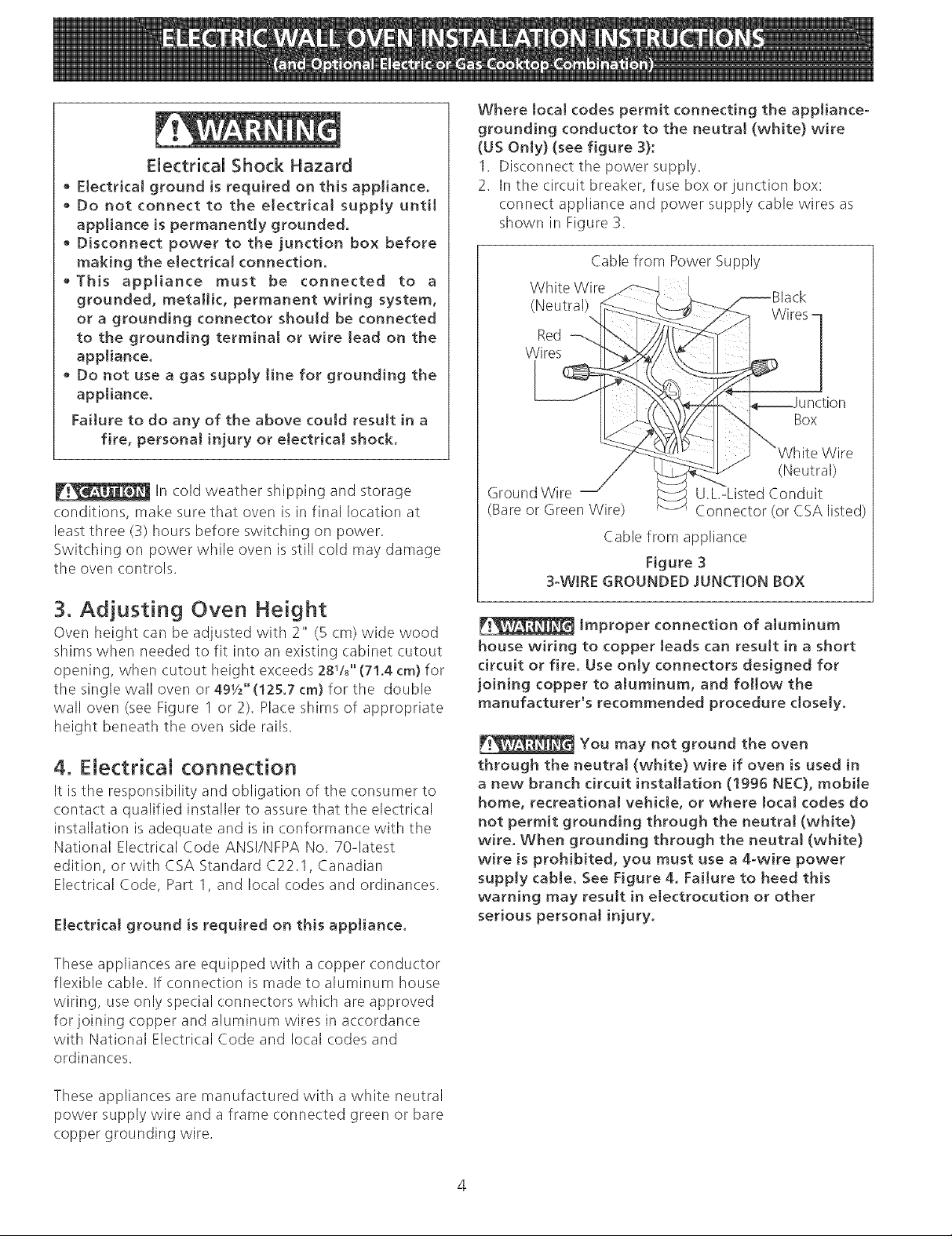
Where local codes permit connecting the appliance-
grounding conductor to the neutra[ (white) wire
(US Only) (see figure 3):
1. Disconnect tile power supply.
2. In the circuit breaker, fuse box or junction box:
connect appliance and power supply cable wires as
shown in Figure 3.
Cable from Power Supply
White Wire
(Neutral)
%
Red
Wires
Wires [
Box
Wire
(Neutral)
Ground Wire U.L-Listed Conduit
(Bare or Green Wire) Connector (or CSA listed)
Cable from appliance
Figure 3
3-WIRE GROUNDED JUNCTION BOX
3. Adjusting Oven Height
Oven height can be adjusted with 2" (5 cm) wide wood
shims when needed to fit into an existing cabinet cutout
opening, when cutout height exceeds 28!/8" (71.4 cm) for
tile single wall oven or 491/2`'(125.7 cm) for the double
wall oven (see Figure 1 or 2). Place shims of appropriate
height beneath the oven side rails.
4. Electrical connection
It is the responsibility and obligation of the consumer to
contact a qualified installer to assure that the electrical
installation is adequate and is in conformance with the
National Electrical Code ANS!/NFPA No. 70qatest
edition, or with CSA Standard C22.1, Canadian
Electrical Code, Part 1, and local codes and ordinances.
Electrical ground is required on this appliance.
These appliances are equipped with a copper conductor
flexible cable. If connection is made to aluminum house
wiring, use only special connectors which are approved
forjoining copper and aluminum wires in accordance
with National Electrical Code and local codes and
ordinances.
__ Improper connection of aluminum
house wiring to copper leads can result in a short
circuit or fire. Use only connectors designed for
joining copper to aluminum, and follow the
manufacturer's recommended procedure dose[yo
You may not ground the oven
through the neutral (white) wire if oven is used in
a new branch circuit installation (1995 NEC), mobi[e
home, recreational vehicle, or where local codes do
not permit grounding through the neutra[ (white)
wire. When grounding through the neutra[ (white)
wire is prohibited, you must use a 4-wire power
supply cable. See Figure 4. Failure to heed this
warning may result in electrocution or other
serious personal injury.
These appliances are manufactured with a white neutral
power supply wire and a frame connected green or bare
copper grounding wire.
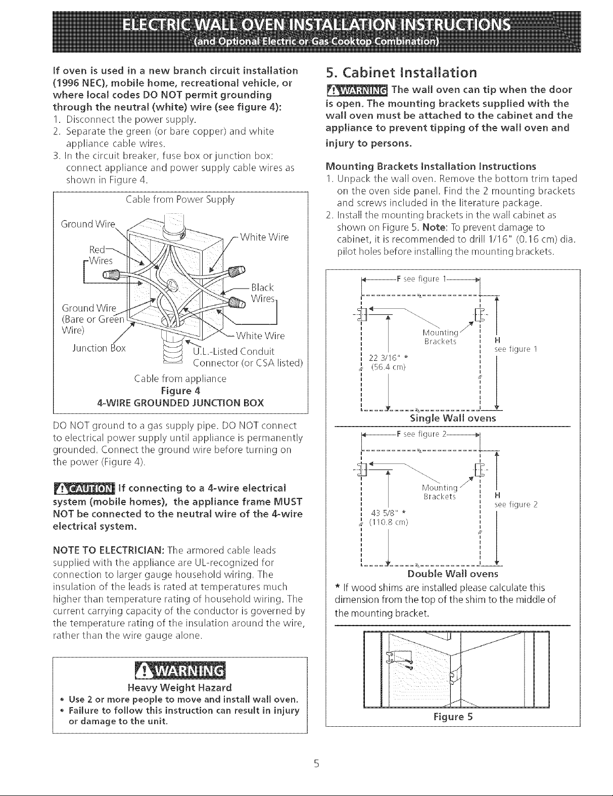
if oven is used in a new branch circuit installation
(!995 NEC), mobile home, recreational vehicle, or
where local codes DO NOT permit grounding
through the neutra! (white) wire (see figure 4):
1. Disconnect the power supply.
2. Separate the green (or bare copper) and white
appliance cable wires.
3. In the circuit breaker, fuse box or junction box:
connect appliance and power supply cable wires as
shown in Figure 4.
Cable from Power Supply
Ground Wire
Wire
Wires
Black
Ground Wire
(Bare or
Wire)
Junction Box
U.L.-Listed Conduit
Connector (or CSA listed)
Cable from appliance
Figure 4
4-WIRE GROUNDED JUNCTtON BOX
DO NOT ground to a gas supply pipe. DO NOTconnect
to electrical power supply until appliance is permanently
grounded. Connect the ground wire before turning on
the power (Figure 4).
5. Cabinet Installation
The wall oven can tip when the door
[s open. The mounting brackets supplied with the
wall oven must be attached to the cabinet and the
appliance to prevent tipping of the wall oven and
injury to persons.
Mounting Brackets Installation Instructions
1. Unpack the wall oven. Remove the bottom trim taped
on the oven side panel. Find the 2 mounting brackets
and screws included in the literature package.
2. Install the mounting brackets in the wall cabinet as
shown on Figure 5. Note: Toprevent damage to
cabinet, it is recommended to drill 1/16" (0.16 cm) dia.
pilot holes before installing the mounting brackets.
I XX
F see figure 1_
H
T
Mountinc
Brackets H
22 3/16" *
(56.4 cm)
Single Wall ovens
see figure 1
If connecting to a 4-wire electrical
system (mobile homes), the appliance frame MUST
NOT be connected to the neutrat wire of the 4-wire
electrical system.
NOTE TO ELECTRICIAN: The armored (:able leads
supplied with the appliance are UUrecognized for
connection to larger gauge household wiring. The
insulation of the leads is rated at temperatures much
higher than temperature rating of household wiring. The
current carrying capacity of the conductor is governed by
the temperature rating of the insulation around the wire,
rather than the wire gauge alone.
Heavy Weight Hazard
Use 2 or more people to move and install wall oven.
Failure to follow this instruction can result in injury
or damage to the unit.
Brackets
43 5/8" *
(110,8 cm)
H
see figure 2
Double Wail ovens
* If wood shims are installed please calculate this
dimension from the top of the shim to the middle of
the mounting bracket.
Figure 5
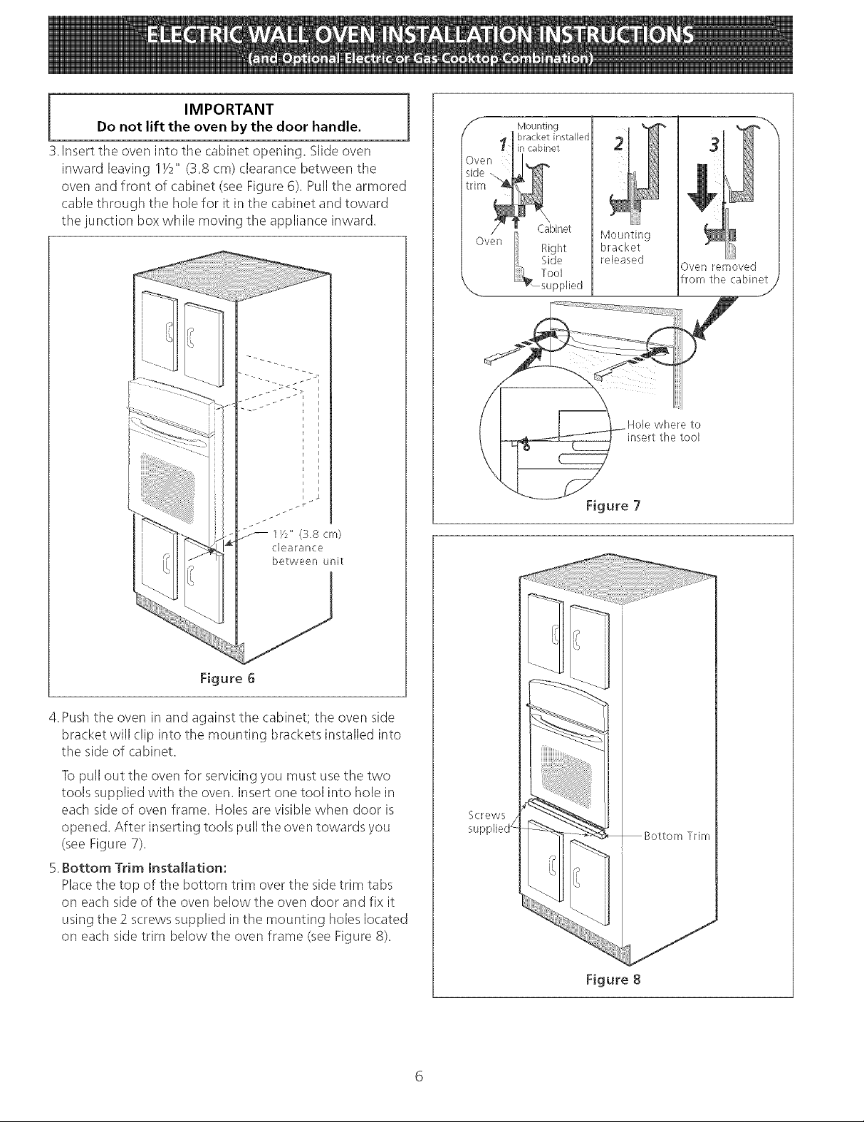
IMPORTANT
Do not lift the oven by the door handle.
3.Insert the oven into the cabinet opening, Slide oven
inward leaving IY2" (3,8 cm) clearance between the
oven and front of cabinet (seeFigure 6), Pull tile armored
cable through tile hole for it in tile cabinet and toward
tile junction box while moving the appliance inward.
S Mounting
Oven
side _,
trim _1
\--.. i_su pplied I
bracket installed
I I in cabinet
/_ Cabinet
Oven
Right
Side
Tool
Mounting
bracket
released
Hole where to
insert the tool
31
1
Oven removed
from the cabinet
J
1/_" (3.8 cm)
clearance
between unit
Figure 6
4.Push the oven in and against the cabinet; the oven side
bracket will clip into the mounting brackets installed into
the side of cabinet.
Topull out the oven for servicing you must use the two
tools supplied with the oven. Insert one tool into hole in
each side of oven frame. Holes are visible when door is
opened. After inserting tools pull the oven towards you
(see Figure 7),
5.Bottom Trim Installation:
Placethe top of the bottom trim over the side trim tabs
on each side of tile oven below the oven door and fix it
using the 2 screws supplied in tile mounting holes located
on each side trim below the oven frame (see Figure 8).
Figure 7
Screws
Figure 8
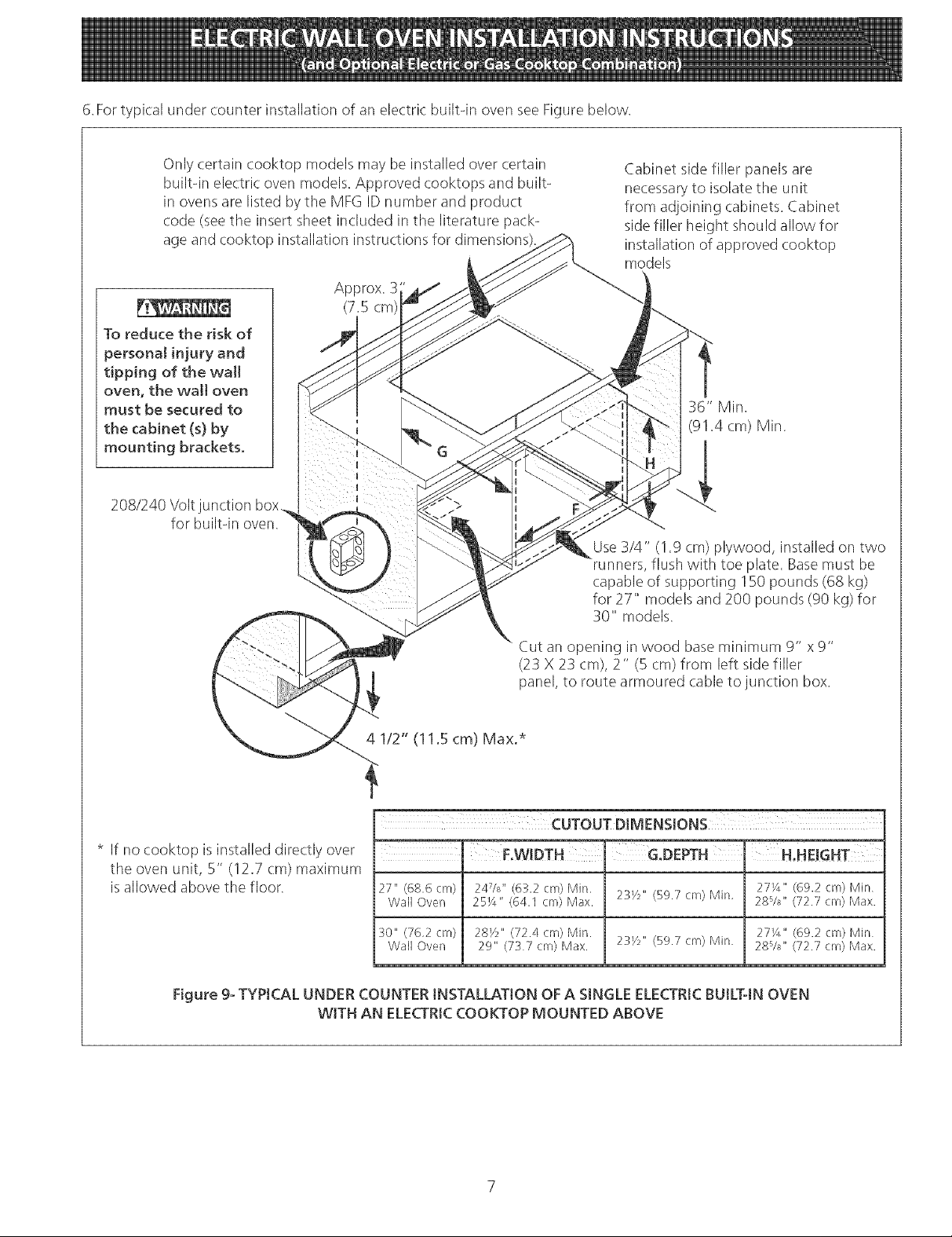
6.FortypicalundercounterinstallationofanelectricbuiltqnovenseeFigurebelow.
Onlycertaincooktopmodelsmaybeinstalledovercertain
builtqnele(tri(ovenmodels.Approvedcooktopsandbuilt-
inovensarelistedbytheMFGIDnumberandproduct
code(seetheinsertsheetincludedintheliteraturepack-
ageandcooktopinstallationinstructionsfordimensions
To reduce the risk of
personal injury and
tipping of the wa]l
oven, the walt oven
must be secured to
the cabinet (s) by
mounting brackets.
208/240 Volt junction box
for builtqn oven.
Cabinet side filler panels are
necessaryto isolate the unit
from adjoining cabinets. Cabinet
sidefiller height should allow for
installation of approved cooktop
models
Approx. 3
(7.5 cm)
36" Min.
(91.4 cm) Min.
4
Use3/4" (! .9 cm) plywood, installed on two
runners, flush with toe plate. Basemust be
capable of supporting 150 pounds (68 kg)
for 27" models and 200 pounds (90 kg) for
30" models.
* If no cooktop is installed directly over
the oven unit, 5" (12.7 cm) maximum
is allowed above the floor.
Figure 9- TYPICAL UNDER COUNTER INSTALLATION OFA SINGLEELECTRICBUILT-IN OVEN
WITH AN ELECTRICCOOKTOP MOUNTED ABOVE
Cut an opening in wood baseminimum 9" x9"
(23 X 23 cm), 2" (5 cm) from left side filler
panel, to route armoured cable to junction box.
4 1/2" (11.5 cm) Max.*
' F°WIDTH H,HDGHT
27" (68,6 cm) 24%" (63,2 cm) blin. 27X" (69.2 cm) Min
Wall Oven 25X" (64.1 cm) Max. 23Y2" (59.7 cm) Min, 28%" (72.7 cm) Max.
:10" (76,2 cm) 28Y2" (72.4 cm) Mir/. 27X" (69.2 cm) Min
Wall Oven 29" (737 cm) Max. 23_//' (59.7 cm) Min 28%" (72.7 cm) Max.
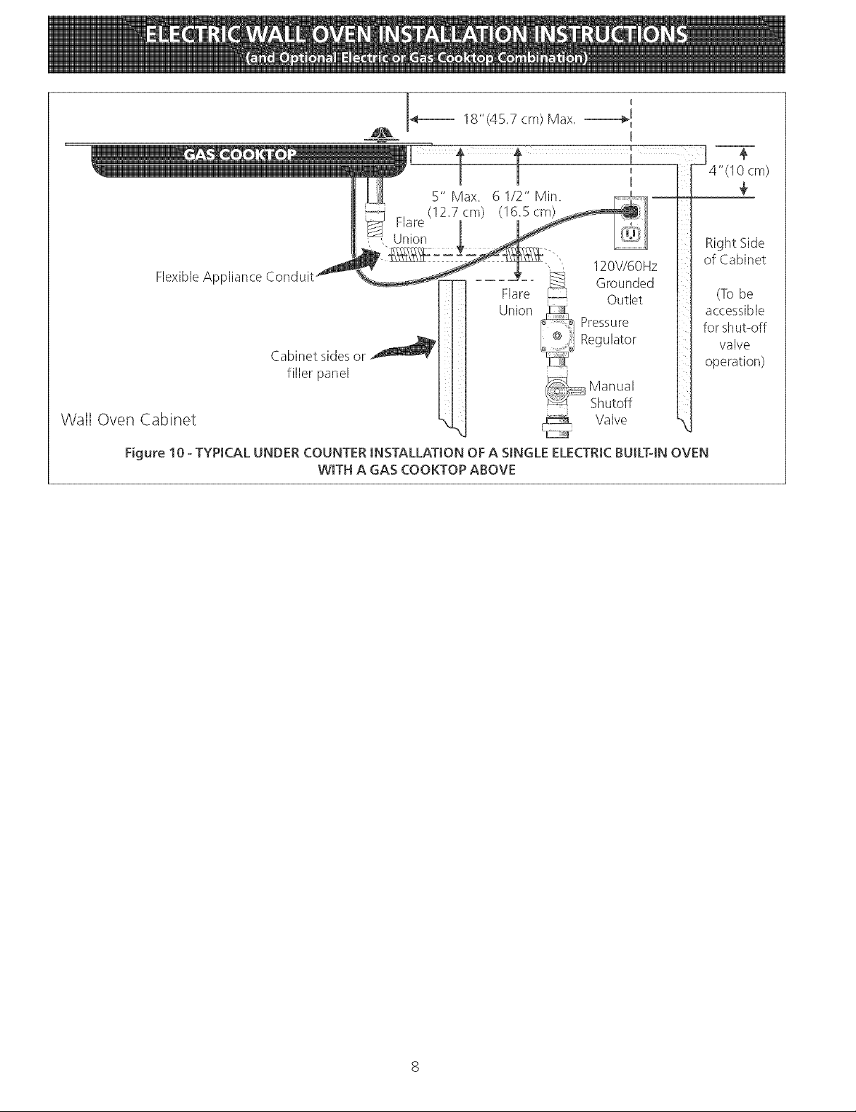
FlexibleApplianceConduit_
Wail Oven Cabinet
Figure 10 - TYPICAL UNDER COUNTER INSTALLATION OFA SINGLE ELECTRICBUILT-IN OVEN
__ 4---- 18"(4E7cm)Max.
fillerpanel
WITH A GAS COOKTOP ABOVE
Union
E
I1 Manual
Pressure
Regulator
Shutoff
Valve
cm)
Right Side
of Cabinet
(To be
accessible
for shut-off
valve
operation)
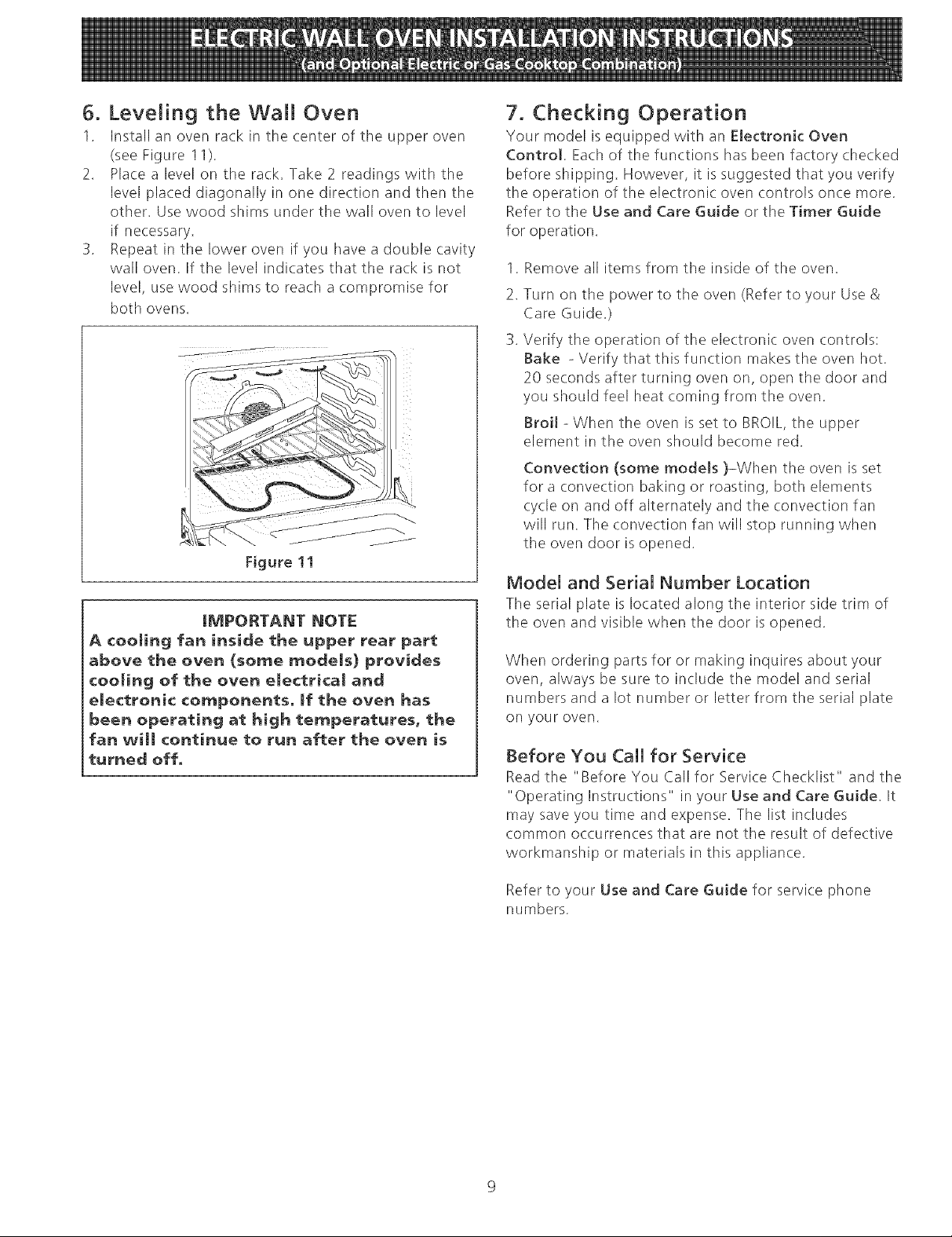
6. LeveJing the WaJJ Oven
1. Install an oven rack in the center of the upper oven
(see Figure 11).
2. Place a level on the ra(k. Take 2 readings with the
level placed diagonally in one direction and then the
other. Usewood shims under the wall oven to level
if necessary.
3. Repeat in the lower oven if you have a double cavity
wall oven. If the level indicates that tile ra(k is not
level, use wood shims to reach a compromise for
both ovens.
Figure 11
IMPORTANT NOTE
A ¢ooJing fan inside the upper rear part
above the oven (some modeJs) provides
¢ooJing of the oven eJectrical aria
eJectroni¢ components, If the oven has
been operating at high temperatures, the
fan will continue to run after the oven is
turned off,
7. Checking Operation
Your model is equipped with an EJectronic Oven
Control Ea(h of tile functions has been factory checked
before shipping. However, it is suggested that you verify
tile operation of the electronic oven controls once more.
Refer to the Use and Care Guide or the Timer Guide
for operation.
.
Remove all items from the inside of the oven.
2.
Turn on the power to tile oven (Refer to your Use &
Care Guide.)
Verify the operation of the electronic oven controls:
Bake - Verify that this function makes the oven hot.
20 seconds after turning oven on, open the door and
you should feel heat coming from the oven.
Broil - When the oven is set to BROIL,tile upper
element in tile oven should become red.
Convection (some models )-When the oven is set
for a convection baking or roasting, both elements
cycle on and off alternately and the convection fan
will run. The convection fan will stop running when
the oven door is opened.
Model and Serial Number Location
The serial plate is located along the interior side trim of
the oven and visible when tile door is opened.
When ordering parts for or making inquires about your
oven, always be sure to include tile model and serial
numbers and a lot number or letter from the serial plate
on your oven.
Before You Call for Service
Read the "Before You Call for Service Che(klist" and tile
"Operating Instructions" in your Use and Care Guide. It
may save you time and expense. Tile list includes
common occurrences that are not tile result of defective
workmanship or materials in this appliance.
Refer to your Use and Care Guide for service phone
numbers.
 Loading...