


HANDBOOK HOOD FSW908TC BK/XS 9925072 110.0019.383 updated JANUARY 2010
CONTROLS : Electronic –Low -tension
CONTROLS : PUSH BUTTONS KEYTOUCH CONTROL MOTOR : NR 01 330 W
TOTAL POWER : 370 W
FLOW RATE - FREE DELIVERY : 920 M3/H MAX FLOW RATE IEC 61591 850 M3/H MAX PRESSURE 440 PA MAX
SOUND POWER(IEC 60704-2-13): 66 DBA
NO SPEED POSITIONS : N0 8 + BOOST
LAMPS : NR 02 HALOGEN LAMPS X 20 W each one LIGHTING SYSTEM CAN BE MODIFIED UP TO FIVE LEVELS. GREASE FILTER : METAL CASSETTE
DIAMETER : 150 MM
IMPUT VOLTAGE 230V -50 HZ
CONTENTS:
TECHNICAL DATA DRAWING
ELECTRICAL CONNECTION
METAL GREASE FILTERS
HOOD BODY MOUNTING
CONTROLS HOW IT WORKS CHARCOAL FILTER SUBSTITUTION OF THE CHARCOAL FILTER REPLACING THE FUSE
LIGHT REPLACEMENT LIST SPARE PARTS EXPLODED VIEW WIRING DIAGRAM
1

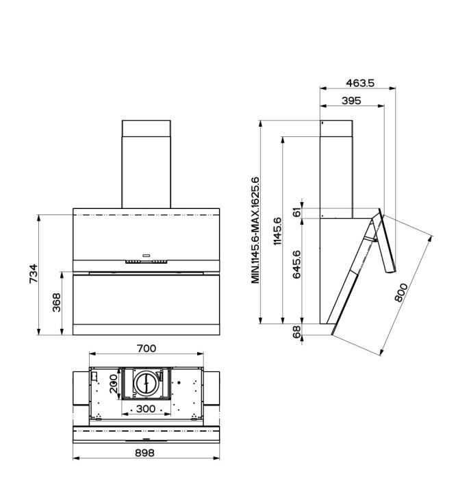
TECHNICAL DATA
SPEED |
|
BOOST |
|
|
8 6 |
7 5 |
4 |
3 |
2 |
1 |
Q |
|
MAX 750 |
|
650920 |
550 |
480 |
410 |
350 |
280 |
200 |
Q |
IEC |
700 |
850 |
620 |
530 |
460 |
390 |
330 |
265 |
190 |
P |
440 |
420 |
|
400 |
390 |
360 |
320 |
280 |
200 |
100 |
W |
330 |
220 |
|
180 |
135 |
110 |
90 |
70 |
50 |
35 |
DBA |
|
66 61 |
|
58 |
55 |
52 |
49 |
46 |
42 |
35 |
2

3
4
ELECTRICAL CONNECTION •
Connect the hood to the mains through a two-pole switch having a contact gap of at least 3 mm.
• Remove the grease filters (see paragraph Maintenance) being sure that the connector of the feeding cable is correctly inserted in the socket placed on the side of the fan.
Metal grease filters
Metal filters can be washed also in a dish machine. They need to be washed every time a drop-symbol appears in the display or at least every two months. In case of very frequent use these have to be washed even more often. Alarm reset • Press the G-key for at least 2 seconds.
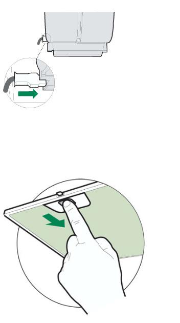
Cleaning
•Open the comfort panel.
•Remove the filters one by one by pushing them backwards and pulling them down contemporaneously.
•Wash the filters. Pay attention not to bend them. Make sure that filters are completely dry before putting them into their seat. (a possible modification of the filter surface doesn’t influence its efficiency).
•Place the filters again into their seats and make sure that the handle of the filter remains outside.
•Close the comfort panel.
5
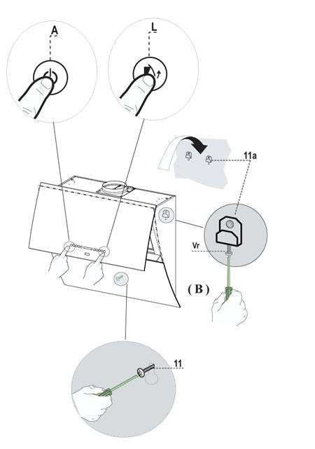
Hood body mounting
Firstly, it is necessary to adjust the two Vr-screws of the 11abrackets, at minimun (B).
•Hang the hood body on the two brackets 11a.
•Connect the hood to the mains supply by means of a bipolar switch with at least 3 mm contact gap.
•Press the “A”-key for one second (see Part USE) to open the upper panel.
•Remove the metal filters.
•In order to align the hood it is necessary to adjust the Vr-screws from inside the hood.
•Fasten the safety screw 11.
•Fit again the metal filters into their seats and close the upper panel by pressing “L”-key for one second (see Part USE).
•Disconnect the hood from the mains supply. Attention: the upper panel stops if any barrier occurs in its way during the panel opening or closing.
To open the panel it is enough to remove the barrier and press the key once again.
6
 Loading...