


Table of Contents
Section 2 – Slide-In Refrigerator Service Manual
Section |
|
|
|
Last |
Number |
Content/Service Operation |
Page No. |
Updated |
|
2.1 |
Trouble Shooting Table |
Page 17-18 |
|
3-4-09 |
2.2 |
Parts List & Component Diagrams |
Page 19 |
|
4-4-06 |
2.3 |
Electric Schematic |
Page 20 |
|
3-9-09 |
|
[General Part Replacement] |
|
|
|
2.4 |
General Service Instructions & Warnings |
Page 21 |
|
3-4-09 |
2.5 |
Door Gasket Replacement |
Page 22 |
12 |
-19-08 |
2.6 |
Digital Temperature Display Replacement |
Page 23 |
12 |
-18-08 |
2.6A |
Temperature Display Battery Replacement |
Page 24 |
|
3-4-09 |
2.7 |
Power ON/OFF Switch Replacement |
Page 25 |
12 |
-18-08 |
2.8 |
Replace Door Hinges |
Page 26 |
12 |
-18-08 |
|
[Part or Component Adjustments] |
|
|
|
2.9 |
Reverse Door Hinges/Change Door Swing |
Page 27 |
12 |
-18-08 |
2.10 |
Thermostat Adjustment |
Page 28 |
12 |
-19-08 |
2.11 |
Temperature Display Calibration |
Page 29 |
12 |
-19-08 |
|
[Refrigeration System Repair & Replacement] |
|
|
|
2.12 |
Condenser Fan Motor Replacement |
Page 30-31 |
12 |
-23-08 |
2.13 |
Thermostat Replacement |
Page 32-33 |
12 |
-19-08 |
2.14 |
Evaporator Fan Motor Replacement |
Page 34-35 |
|
3-4-09 |
2.15 |
Evaporator Coil Replacement |
Page 36-37 |
12 |
-26-08 |
2.16 |
Start Relay & Start Capacitor Replacement |
Page 38 |
|
3-4-09 |
2.17 |
Check Refrigerant Pressure/Check for Leak |
Page 39 |
|
3-4-09 |
2.18 |
Repair System [Refrigerant] Leak |
Page 40 |
12 |
-29-08 |
2.19 |
Expansion Valve Replacement |
Page 41-42 |
|
3-4-09 |
2.20 |
Replace Compressor |
Page 43-44 |
12 |
-29-08 |
Updated 3-4-09
Slide-In Refrigerator Operating & Service Manual |
Page 1 |

|
|
SIR Service Section |
Advanced Troubleshooting Guide / Section 2.1 |
|||
|
|
|
|
|
|
|
|
|
The Problem |
|
Possible Cause |
What To Check & Do |
|
|
|
Main Power Not |
Power not available to |
Breaker OK? Yes = Continue; No = Call electrician |
|
|
|
|
|
|
|||
|
Receptacle OK? Yes = Continue; No = Call |
|
||||
|
|
“ON” |
unit? |
|
||
|
|
|
|
|
electrician |
|
|
|
|
Power cord OK? |
Yes = Continue; No = Replace power cord |
|
|
|
|
|
|
|
|
|
|
|
|
Power switch OK? |
Yes = Continue; No = Replace switch per Section |
|
|
|
|
|
|
|
2.7 |
|
|
|
|
|
|
Unplug refrigerator power cord for 1 hour, then |
|
|
|
|
Compressor thermal |
retry. If problem reoccurs: |
|
|
|
|
|
overload tripped? |
1. Ensure air filter is maintained per PM |
|
|
|
|
|
|
|
Operating Instructions |
|
|
|
Main Power “ON” |
|
|
2. Ensure condenser coil is clear of debris and |
|
|
|
But Compressor |
|
|
cleaned, per PM Operating Instructions |
|
|
|
Does Not Run |
Condenser unit is not |
Check junction box mounted on side wall of service |
|
|
|
|
|
plugged in. |
compartment for compressor power cord. |
|
|
|
|
|
Thermostat defective? |
Replace thermostat per Section 2.13. |
|
|
|
|
|
|
|
|
|
|
|
|
Defective Start Relay |
Per Section 2.16: |
|
|
|
|
|
and/or Start Capacitor |
1. Replace Capacitor first. Try starting |
|
|
|
|
|
|
|
compressor. If it starts, verify working |
|
|
|
|
|
|
temperature. If compressor doesn’t start: |
|
|
|
|
|
|
2. Replace Start Relay. Try starting |
|
|
|
|
|
|
compressor. If it starts, verify working |
|
|
|
|
|
|
temperature. If NO, Continue: |
|
|
|
|
Compressor defective? |
Replace Compressor per Section 2.20 |
|
|
|
|
|
Temperature display |
Verify calibration of digital temperature display with |
|
|
|
|
|
needs to be calibrated? |
calibrated thermometer, per Section 2.11. If out of |
|
|
|
|
|
|
|
calibration, adjust digital display. If OK, Continue. |
|
|
|
Unit Runs, But |
Thermostat needs |
Adjust thermostat setting, per Section 2.10 |
|
|
|
|
adjustment? |
|
|
||
|
|
Refrigerator |
One or both doors |
Inspect door gaskets for damage. If needed, |
|
|
|
|
Compartment Does |
leaking cold air |
replace per Section 2.5 |
|
|
|
|
Not Cool Down To |
Thermostat is |
Replace thermostat, per Section 2.13 |
|
|
|
|
34 - 40° F |
defective? |
|
|
|
|
|
|
Condenser fan not |
Replace condenser fan motor per Section 2.12 |
|
|
|
|
|
functioning |
|
|
|
|
|
|
Low refrigerant |
Check system Discharge and Suction Pressures, |
|
|
|
|
|
pressure? |
per Section 2.17. |
|
|
|
|
|
|
|
1. If Discharge and Suction pressure are low, |
|
|
|
|
|
|
check for system leak per Section 2.17. |
|
|
|
|
|
|
2. If Discharge is High and is Suction Low, |
|
|
|
|
|
|
there is a probable line restriction. Inspect |
|
|
|
|
|
|
for kinked or restricted lines. If found, |
|
|
|
|
|
|
replace. If not found, replace Expansion |
|
|
|
|
|
|
Valve, per Section 2.19. |
|
|
|
For Technical Support, Call 800-537-2653. |
Copyright 2009 Franke, Inc. All rights reserved. |
|||

|
SIR Service Section |
Advanced Troubleshooting Guide / Section 2.1 |
||||
|
|
|
|
|
|
|
|
The Problem |
|
Possible Cause |
|
What To Check & Do |
|
|
Unit Runs, But |
System leak? |
1. |
Check for system leak, per Section 2.17. If |
|
|
|
Refrigerator |
|
|
|
none detected, continue. If leak detected: |
|
|
Compartment Does |
|
|
2. |
Repair or replace lines and recharge system, |
|
|
Not Cool Down To |
|
|
|
per Section 2.18 |
|
|
34 - 40° F [Cont.] |
|
|
|
|
|
Rev. 2 3/09
For Technical Support, Call 800-537-2653. |
Copyright 2009 Franke, Inc. All rights reserved. |

SIR Service Section |
Parts List & Component Diagrams / Section 2.2 |
Rev. 1 4/06
For Technical Support, Call 800-537-2653. |
Copyright 2009 Franke, Inc. All rights reserved. |
SIR Service Section |
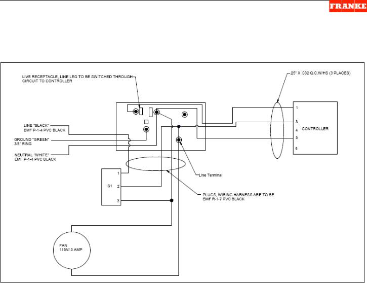
Electric Schematics / Section 2.3 |
Wiring Harness – Refrigeration Circuit (Drawing No. 19000864)
NOTE: Models with a mechanical temperature controller will not have numbered terminals on the controller and will not have a neutral (white) wire to temperature controller.
Rev. 2 3/09
For Technical Support, Call 800-537-2653. |
Copyright 2009 Franke, Inc. All rights reserved. |
SIR Service Section |
General Requirements / Section 2.4 |
2.4Introduction to Slide-In Refrigerator Service
The SIR Module is designed to mount under a Prep Table. It has two refrigerator compartment doors to provide easy access to contents, from either side. The unit FRONT is considered the side with the power switch and temp. display.
The Basics:
1)Technicians should be authorized to work on Franke Equipment and be EPA Certified and qualified to diagnose and repair refrigeration equipment.
2)This Slide-In Refrigerator Module operates on 120-volt power and is provided with a grounded plug and 8’ power cord, which typically plugs into a table outlet.
WARNING:
Unplug unit from its120-volt table mounted power source whenever servicing electrical components or removing service access panels. Failure to unplug unit may result in electric shock, burns or death.
3)The SIR refrigeration system is charged with 23 ounces (650 gm) of ozone-safe R404A refrigerant. Only use R404A refrigerant when recharging this unit.
4)A fully functional SIR will operate at safe food holding temperatures between: 34 F minimum and 40 F maximum (1 C and 4 C).
5)It is typical for this unit to take from 30 to 45 minutes to reach the normal operating temperature range, after a prolonged shutdown. The compressor will cycle on-and- off during this cool-down period.
Suggested [On-Truck] Repair Parts:
Part No. |
Description |
Qty. |
3587645 |
Door Gasket |
2 ea. |
3586246 |
Digital Temperature Display |
1 ea. |
3126151 |
Power On/OFF Switch |
1 ea. |
19000801 |
Power cord set 120-V, 15 AMP, 10’ |
1 ea. |
18001476 |
Door Hinge [Upper] |
2 ea. |
18001477 |
Door Hinge [Lower] |
2 ea. |
19000023 |
Thermostat [Danfoss 077B1262] |
1 ea. |
3589854 |
Condenser Fan Motor |
1 ea. |
19000454 |
Evaporator Fan Motor |
1 ea. |
19001041 |
Evaporator Coil |
1 ea. |
19000884 |
Evaporator Coil Assembly |
1 ea. |
19000024 |
Start Capacitor (117µ5025) |
1 ea. |
19001083 |
Start Relay (117µ4127) |
1 ea. |
19001189 |
Expansion Valve |
1 ea. |
19001079 |
Compressor Only |
1 ea. |
19000881 |
Condenser/Compressor Package |
1 ea. |
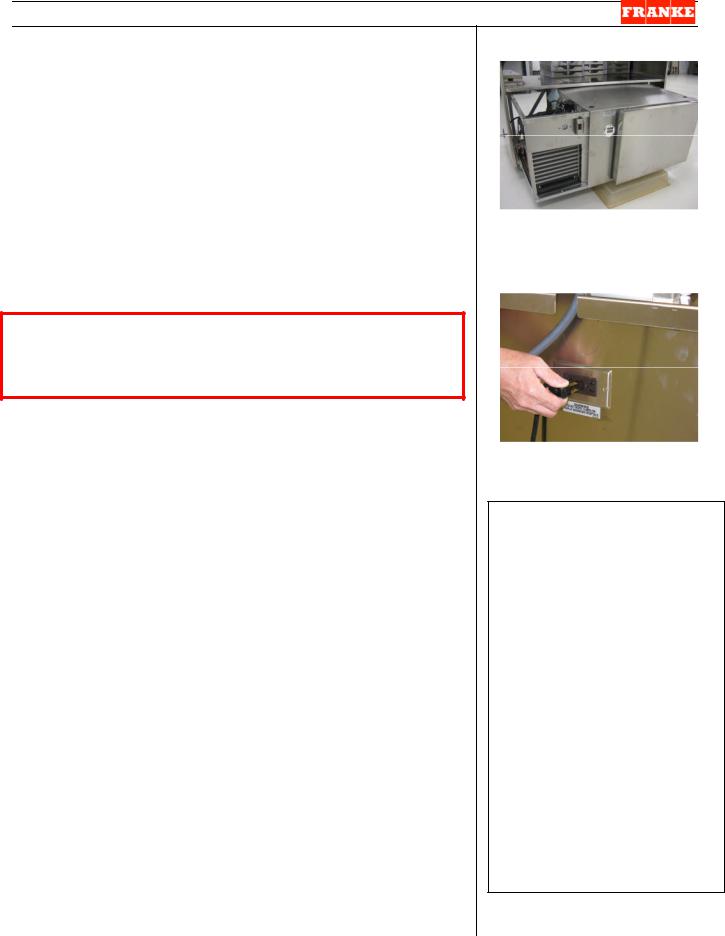
[Photo 1]
The SIR Unit mounts under a prep table & can be pulled out to provide easy top & side access.
[Photo 2]
The SIR plugs into an outlet on the side of the prep table.
Tools Required:
3/8” flat blade screwdriver
¼” flat blade screwdriver
1/16” “mini” screw driver
Medium Phillips screwdriver
Small Phillips screwdriver
¼” nut driver
5/16” nut driver
10 mm box wrench or socket
11 mm box wrench or socket
¼” socket wrench/ratchet
Phillips bit for ratchet
Needle nose pliers
Refrigerant recovery tank & fittings
Nitrogen charge tank
R404A Refrigerant
Tubing cutter
Brazing torch, etc.
Calibrated thermometer
Electronic leak detector
Manifold pressure gauge
Rev. 3 3/09
For Technical Support, Call 800-537-2653. |
Copyright 2009 Franke, Inc. All rights reserved. |
SIR Service Section |
Parts Replacement / Section 2.5 |
2.5SIR Door Gasket Replacement [Part No. 3587645]
1)The Slide-In Refrigerator should be unplugged and the compartment emptied, before proceeding.
2)Open and inspect the one-piece magnetic gasket on both doors. If a gasket is torn or crushed so that it doesn’t completely seal around the full door perimeter, it should be replaced. To replace:
3)Remove the one-piece gasket from the slotted plastic extrusion built into the back of each refrigerator door. [NOTE: Plastic extrusion can be damaged using a razor knife to separate the old gasket from its retaining tailpiece. If a brittle tailpiece separates from the main gasket, remove it by pulling toward each corner using small needle nose pliers.]
4)Clean any grime from area under the old gasket.
5)Take the new gasket [P/N: 3587645] and insert the tailpiece into the gasket-mounting slot. Align the corners and start at the top of the door. Continue around the door perimeter until it is completely seated.
6)Test the replacement SIR Door Gasket by:
7)Close the door and visually check the door seal and fit.
8)Plug power cord into120-volt outlet and turn ON power switch. Allow compressor to draw down Refrigerator Compartment temperature. Check with your hand around the full door perimeter for any cold air leaks.
Tools Required:
Needle nose pliers
Rev. 2 12/08
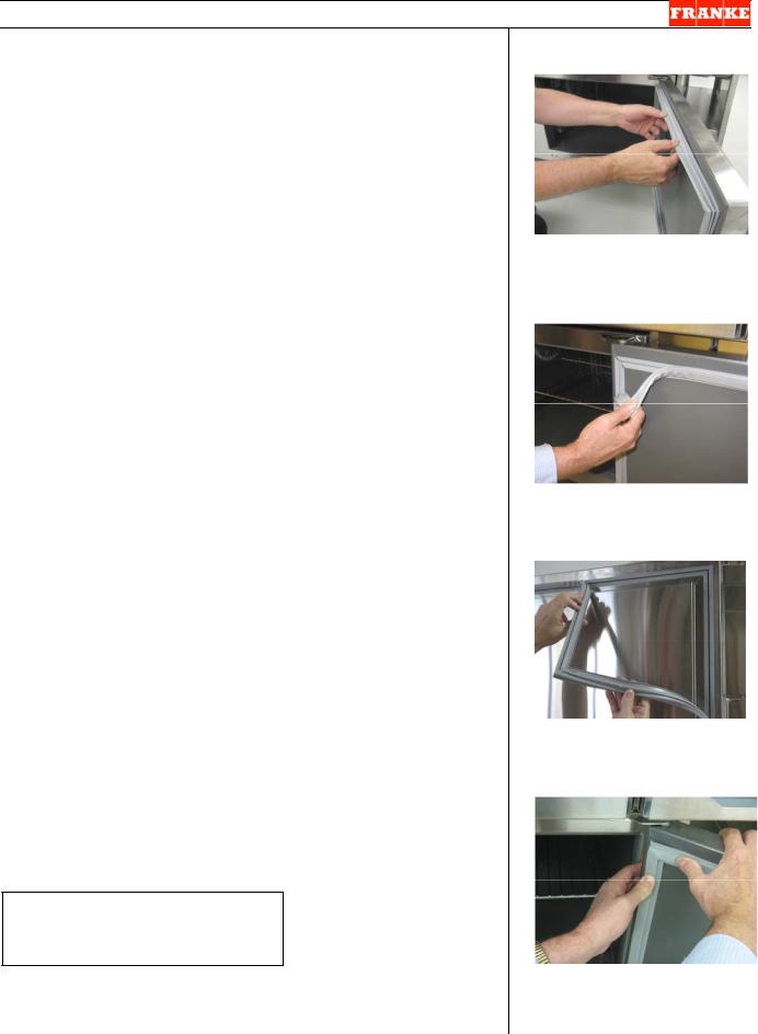
[Photo 1]
Inspect both door gaskets for cuts, cracks or breaks.
[Photo 2]
Pull old gasket tailpiece out of plastic door extrusion.
[Photo 3]
Align corners and insert new gasket tailpiece in plastic slot.
[Photo 4]
Use thumb pressure to snap gasket into slot.
For Technical Support, Call 800-537-2653. |
Copyright 2008 Franke, Inc. All rights reserved. |
SIR Service Section |
Parts Replacement / Section 2.6 |
2.6Digital Temperature Display Replacement [Part No. 3586246]
1)Turn OFF power switch.
2)Disconnect power at table outlet. [Pull 120-Volt plug.]
3)Using a 1/8” [3-4 mm] flat blade screwdriver, remove the three screws from the temperature display bezel and pull out display assembly to extent of wire harness.
4)From inside the refrigerator compartment [bulb is mounted near evaporator cover], use a small ratchet with a Phillips screwdriver bit to loosen and remove the two screws on the temperature bulb mounting clip.
5)Remove bulb from mounting clip and pull connecting wire and bulb out through cabinet front.
6)Remove new Digital Temperature Display [P/N 3586246] from any protective packaging, uncoil 6-8” (15-20 cm) of bulb wire and insert bulb thought penetration in interior compartment wall.
7)From inside compartment pull out bulb, position down into mounting clip and secure clip to wall using two screws removed earlier. (See Photo 4 for bulb position)
8)Coil any excess bulb wire into display cavity, insert temperature display and secure with the three mounting screws removed earlier.
Test the new Digital Temperature Display by:
9)Plug in unit power cord to table 120-volt power supply.
10)Turn power switch ON.
11)The temperature display should show the current compartment temperature and track pull-down to a safe operating temperature range of 34 to 40 F [1 to 4 C].
NOTE: See Section 2.11 for Temperature Display Calibration procedure.
Tools Required:
1/8” [3-4 mm] flat blade screwdriver
Small ratchet with Phillips bit
Rev. 2 12/08
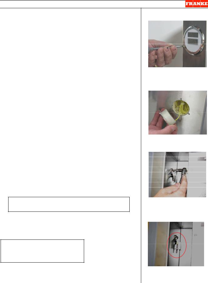
[Photo 1]
Remove the three bezelretaining screws.
[Photo 2]
Pull out plastic display assembly.
[Photo 3]
From inside compartment remove two screws that hold probe mounting bracket.
[Photo 4]
Proper probe mounting position
For Technical Support, Call 800-537-2653. |
Copyright 2008 Franke, Inc. All rights reserved. |
SIR Service Section |
Parts Replacement / Section 2.6A |
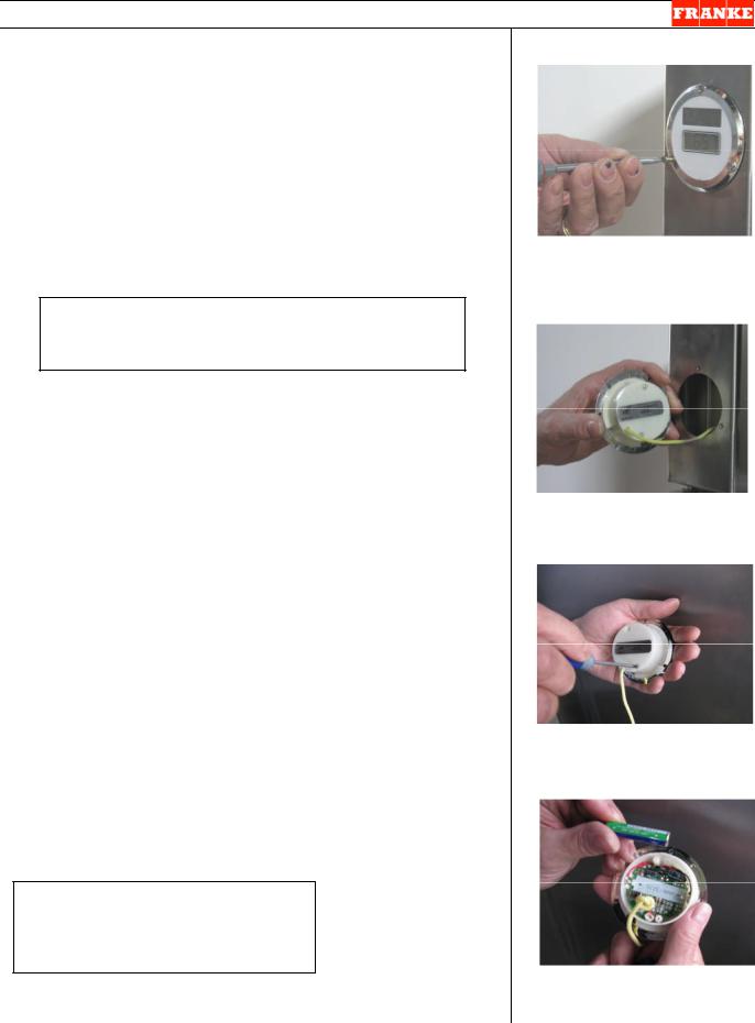
2.6A Temperature Display Battery Replacement
[Standard AAA Alkaline]
1)Using a 1/8” [3-4 mm] flat blade screwdriver, remove the three screws from the temperature display bezel and pull out display assembly to extent of slack in sensor wire.
2)Turn display over and use a small Phillips screwdriver to remove two screws on back of display.
3)Remove cover to access battery compartment.
4)Remove old battery and replace with fresh AAA Alkaline Battery.
NOTE: The small board-mounted control just below the battery can be used to change display reading from degrees F to Degrees C.
5)Replace plastic back and secure with two small Phillips screws removed earlier.
6)Insert temperature display into mounting hole and secure with the three mounting screws removed earlier.
Test the new Digital Temperature Display by:
7)Temperature display should show the current compartment temperature as soon as the battery is properly inserted.
8)If new battery does not revive display, replace Digital Temperature Display [P/N 3586246]. See Section 2.6.
Tools & Supplies Required:
1/8” [3-4 mm] flat blade screwdriver Small Phillips screwdriver
AAA Alkaline Batteries
Rev. 1 3/09
[Photo 1]
Remove the three bezelretaining screws.
[Photo 2]
Pull out plastic display assembly.
[Photo 3]
Use small Phillips screwdriver to remove back cover.
[Photo 4]
Replace using one AAA Alkaline battery.
For Technical Support, Call 800-537-2653. |
Copyright 2009 Franke, Inc. All rights reserved. |
 Loading...