


Wireless Lan Controller
FortiWLC™-500D
QuickStart Guide
Table of contents |
|
Package contents . . . . . . . . . . . . . . . . . . . . . . . . . . . . . . . . . . . . . . . . . . . . . . . . . . . . . |
. 1 |
Rack mounting . . . . . . . . . . . . . . . . . . . . . . . . . . . . . . . . . . . . . . . . . . . . . . . . . . . . . . . |
. 2 |
Installing SFP transceivers . . . . . . . . . . . . . . . . . . . . . . . . . . . . . . . |
. 3. . . . . . . . . . . |
Connecting to FortiWLC . . . . . . . . . . . . . . . . . . . . . . . . . . . . . . . . . . . . . |
.5. . . . . . . . . |
Shutting down . . . . . . . . . . . . . . . . . . . . . . . . . . . . . . . . . . . . . . . . . . . . . . . . |
.7. . . . . . . |
Registering your product . . . . . . . . . . . . . . . . . . . . . . . . . . . . . . . . . . . . . |
. 8. . . . . . . . |
Ports & LEDs . . . . . . . . . . . . . . . . . . . . . . . . . . . . . . . . . . . . . . . . . . . . . . . . . . . . . . . . . . |
. 9 |
Replacing a PSU .. .. .. .. .. .. .. .. .. .. .. .. .. .. .. .. .. .. .. .. .. .. .. .. .. .. .. .. .. .. .. .. .. .. .. .. .. .. .. .. .. .. .. .. .. .. .. .. .. .. .. .. .. .. |
11 |
Cautions and warnings . . . . . . . . . . . . . . . . . . . . . . . . . . . . . . . . . . . . . . |
12. . . . . . . . . |
Regulatory notices . . . . . . . . . . . . . . . . . . . . . . . . . . . . . . . . . . . . |
14. . . . . . . . . . . |
License agreement & warranty . . . . . . . . . . . . . . . . . . . . . . . . . . . . . . . . . . . . . . . . |
16 |

Package contents
The box should contain:
FortiWLC-500D appliance FortiWLC-500D QuickStart Guide 2 Power cables
Console cable Ethernet cable
4 Rubber feet
2 Grounding screws
8 Bracket screws
2 Rack mount ears
2 Power C ables C onsole C able |
Ethernet C able |
QuickS tart G uide
FortiWLC 500D
QuickStart Guide
4 Rubber Feet |
2 G rounding |
8 Bracket |
|||
Sc rews |
Sc rews |
||||
|
|
|
|||
|
|
|
|
|
|
|
|
|
|
|
|
1
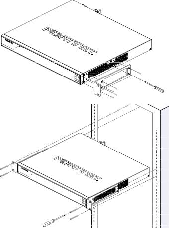
Rack mounting
FortiWLC appliances should be installed in a restricted access location such as a locked data center to ensure their physical security, which is
fundamental to your network security.. Mount the appliance in any standard 19 inch (48..3 cm) rack with the rack-mount brackets..
In a rack, a FortiWLC-500D occupies 1U (1..77 in/4..45 cm)..
•2-post rack: Attach the rack-mount brackets to the middle of each side of appliance so that its weight is distributed evenly..
•4-post rack: Attach the rack-mount brackets to the front of each side of the appliance with flanges facing outwards, towards the notches in the rack..
2

Installing SFP transceivers
If not already installed, install the SFP/SFP+ transceivers that will be used to connect your appliance to the network..
Caution: Do not install or remove SFP transceivers while fiber-optic cables are still attached.. This can cause damage to the cables, cable connectors, and optical interfaces.. It may also prevent the transceiver from latching correctly into the socket..
Note: Installing and removing SFP transceivers can shorten their life.. Do not install or remove transceivers more than is necessary..
To install the SFP transceivers
1.On the appliance’s front panel, remove the caps from SFP cage sockets..
2.Position the SFP transceiver in front of the cage socket so that the extraction lever is level with the socket latch..
Note: SFP cage socket orientation may vary. . Ensure that the SFP transceiver module is correctly oriented..
3.Holding the sides of the SFP transceiver, gently slide it into the cage socket..
Caution: Do not force SFP transceivers into cage sockets. . Force can cause damage. . If the transceiver does not easily slide in and click into place, it may not be aligned correctly or may be upside down. . If this happens, remove the SFP transceiver, realign or rotate it, and try again..
3
4.Press the transceiver firmly into the cage socket with your thumb until it clicks, indicating that it is latched..
5.To verify that the transceiver is latched, grasp its sides and try to pull it out without lowering the extraction lever..
If you can remove the transceiver, it was not latched correctly, and could become accidentally dislodged.. Try again..
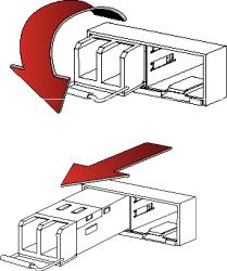
To remove the SFP transceivers
1.Disconnect the fiber optic cable from the transceiver connector..
2.To prevent dust from entering the optical bores, insert clean plugs..
3.To eject the transceiver, pull the extraction lever out and down.. Tip: Instead of using your finger, try a small flat-head screwdriver..
4.Hold the sides of the transceiver and carefully pull it from the cage socket..
5.Replace the cap on the SFP cage socket..
6.Put the removed SFP transceiver into an anti-static bag..
4
Connecting to FortiWLC
If the appliance has a redundant power supply, connect each power cable to a different power source..
You can configure FortiWLC for your network through a connection to command line interface (CLI)..
IMPORTANT |
• |
FortiWLC-500D is supported ONLY from System |
|
|
Director 8..0-SR1 and later.. |
|
• |
SFP support is not available in the 8..0-SR1 |
|
|
release.. |
|
|
|
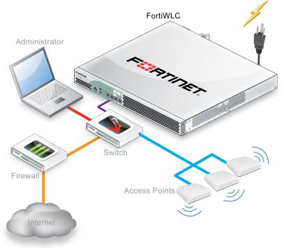
Connect FortiWLC only to your computer until you finish setup.. (If you place FortiWLC in your network before FortiWLC is set up, traffic could be interrupted until setup is complete..) Detailed instructions are in the System Director User Guide..
One typical, basic network topology is shown below..
5
To connect to the CLI via serial console
Requires: Terminal emulator such as PuTTY, Tera Term, or a terminal server
1.Using the console cable, connect the appliance console port to your terminal server or computer..
2. |
On your computer |
or terminal server, start the terminal emulator. . |
|
Use these settings: |
|
• |
Baud rate: |
115200 |
• |
Data bits: |
8 |
• |
Parity: |
None |
• |
Stop bits: |
1 |
•Flow control:None
3.Press Enter on your keyboard to connect to the CLI..
6
 Loading...