


 Loading...
TS→52PRO
Test Set
Users Guide
PN 3394309
January 2009, Rev. 3 10/11
©2009, 2011 Fluke Corporation. Printed in China.
All product names are trademarks of their respective companies.
LIMITED WARRANTY AND LIMITATION OF LIABILITY
Each Fluke Networks product is warranted to be free from defects in material and workmanship under normal use and service. The warranty period for the mainframe is 3 years and begins on the date of purchase. Parts, accessories, product repairs and services are warranted for 90 days, unless otherwise stated. Ni-Cad, NiMH and Li-Ion batteries, cables or other peripherals are all considered parts or accessories. The warranty extends only to the original buyer or end user customer of a Fluke Networks authorized reseller, and does not apply to any product which, in Fluke Networks’ opinion, has been misused, abused, altered, neglected, contaminated, or damaged by accident or abnormal conditions of operation or handling. Fluke Networks warrants that software will operate substantially in accordance with its functional specifications for 90 days and that it has been properly recorded on non-defective media. Fluke Networks does not warrant that software will be error free or operate without interruption.
Fluke Networks authorized resellers shall extend this warranty on new and unused products to end-user customers only but have no authority to extend a greater or different warranty on behalf of Fluke Networks. Warranty support is available only if product is purchased through a Fluke Networks authorized sales outlet or Buyer has paid the applicable international price. Fluke Networks reserves the right to invoice Buyer for importation costs of repair/replacement parts when product purchased in one country is submitted for repair in another country.
Fluke Networks warranty obligation is limited, at Fluke Networks option, to refund of the purchase price, free of charge repair, or replacement of a defective product which is returned to a Fluke Networks authorized service center within the warranty period.
To obtain warranty service, contact your nearest Fluke Networks authorized service center to obtain return authorization information, then send the product to that service center, with a description of the difficulty, postage and insurance prepaid (FOB destination). Fluke Networks assumes no risk for damage in transit.
Following warranty repair, the product will be returned to Buyer, transportation prepaid (FOB destination). If Fluke Networks determines that failure was caused by neglect, misuse, contamination, alteration, accident or abnormal condition of operation or handling, or normal wear and tear of mechanical components, Fluke Networks will provide an estimate of repair costs and obtain authorization before commencing the work.
Following repair, the product will be returned to the Buyer transportation prepaid and the Buyer will be billed for the repair and return transportation charges (FOB Shipping point).
THIS WARRANTY IS BUYER’S SOLE AND EXCLUSIVE REMEDY AND IS IN LIEU OF ALL OTHER WARRANTIES, EXPRESS OR IMPLIED, INCLUDING BUT NOT LIMITED TO ANY IMPLIED WARRANTY OR MERCHANTABILITY OR FITNESS FOR A PARTICULAR PURPOSE. FLUKE NETWORKS SHALL NOT BE LIABLE FOR ANY SPECIAL, INDIRECT, INCIDENTAL OR CONSEQUENTIAL DAMAGES OR LOSSES, INCLUDING LOSS OF DATA, ARISING FROM ANY CAUSE OR THEORY.
Since some countries or states do not allow limitation of the term of an implied warranty, or exclusion or limitation of incidental or consequential damages, the limitations and exclusions of this warranty may not apply to every buyer. If any provision of this Warranty is held invalid or unenforceable by a court or other decision-maker of competent jurisdiction, such holding will not affect the validity or enforceability of any other provision.
4/04-3
Fluke Networks
PO Box 777
Everett, WA 98206-0777
USA
Table of Contents
Title |
Page |
Introduction ........................................................................................................................................................ |
1 |
Registration ......................................................................................................................................................... |
1 |
Contacting Fluke Networks ................................................................................................................................ |
1 |
Safety Information .............................................................................................................................................. |
2 |
Product Features ................................................................................................................................................. |
2 |
Physical Characteristics ....................................................................................................................................... |
3 |
Housing ........................................................................................................................................................ |
3 |
Belt Clips ....................................................................................................................................................... |
3 |
Line Cords ..................................................................................................................................................... |
4 |
Battery .......................................................................................................................................................... |
4 |
Speaker and Speakerphone Microphone ................................................................................................... |
4 |
Audio Controls ............................................................................................................................................. |
4 |
Display and Keypad ..................................................................................................................................... |
7 |
Operation .......................................................................................................................................................... |
12 |
Talk/Monitor Switch .................................................................................................................................. |
12 |
Operating the Test Set in Monitor Mode ................................................................................................. |
12 |
Caller ID ............................................................................................................................................... |
13 |
Operating the Test Set in Talk Mode ....................................................................................................... |
13 |
Originating a Call ............................................................................................................................... |
13 |
Disconnecting a Call ........................................................................................................................... |
13 |
Answering a Call ................................................................................................................................. |
13 |
Ground Start ....................................................................................................................................... |
14 |
Data Lockout Operation ............................................................................................................................ |
14 |
Data Safe Practices ..................................................................................................................................... |
14 |
Data Lockout Override Operation ............................................................................................................ |
15 |
High Voltage Lockout Operation ............................................................................................................. |
15 |
Configuring Your Test Set ......................................................................................................................... |
15 |
Last Number Redial ............................................................................................................................ |
16 |
Program Speed Dialing Numbers ...................................................................................................... |
16 |
Putting a Pause in a Stored Number ................................................................................................. |
16 |
Storing the Last Number Dialed ........................................................................................................ |
16 |
Storing a Number You are Calling .................................................................................................... |
16 |
Dialing a Stored Number ................................................................................................................... |
17 |
Hook Flash Duration ........................................................................................................................... |
17 |
Make Receive-Only Loud Speaker the Default ................................................................................. |
17 |
Speaker/LCD/Test Set Timeout ........................................................................................................... |
18 |
i

TS52PRO Test Set |
|
Users Guide |
|
LCD Backlight ...................................................................................................................................... |
18 |
DTMF Digit Grabbing .......................................................................................................................... |
19 |
Visual ANAC Mode .............................................................................................................................. |
19 |
Factory Defaults .................................................................................................................................. |
19 |
Maintenance ...................................................................................................................................................... |
20 |
Cleaning ...................................................................................................................................................... |
20 |
Replacing the Battery ................................................................................................................................ |
20 |
Replacing or Relocating the Belt Clip ....................................................................................................... |
21 |
Replacing the Line Cord ............................................................................................................................. |
21 |
Removing the Old Line Cord .............................................................................................................. |
21 |
Installing a New Line Cord ................................................................................................................. |
22 |
Accessories (How to Order) ....................................................................................................................... |
23 |
Specifications ..................................................................................................................................................... |
24 |
ii

TS®52PRO Test Set
Introduction
The TS52PRO Test Set is an analog test telephone used by installers, repair technicians and other authorized personnel to test copper wire voice subscriber lines. In addition to providing standard off-hook operations, such as dialing and voice communications, the TS52PRO model has an on-hook Monitor mode that lets the operator listen to the line without disturbing any voice or data signals present. The test set has a speaker for hands-free listening. The test set also has a speakerphone that allows two way conversations while freeing up the operator’s hands for other tasks.
In today’s telecommunications environment, a large number of subscriber lines carry data services. The data services are in the same distribution facilities as voice services. It is not always easy to tell the difference between data and voice services. The TS52PRO Test Set uses unique, patented circuitry that prevents disruption of digital data services if the test set is unintentionally connected to a data line.
Registration
Registering your product with Fluke Networks gives you access to valuable information on product updates, troubleshooting tips, and other support services. To register, fill out the online registration form on the Fluke Networks website at www.flukenetworks.com/ registration.
Contacting Fluke Networks
www.flukenetworks.com
support@flukenetworks.com
+1-425-446-4519
•Australia: 61 (2) 8850-3333 or 61 (3) 9329 0244
•Beijing: 86 (10) 6512-3435
•Brazil: 11 3759 7600
•Canada: 1-800-363-5853
•Europe: +31-(0) 40 2675 600
•Hong Kong: 852 2721-3228
•Japan: 03-6714-3117
•Korea: 82 2 539-6311
•Singapore: 65-6799-5566
•Taiwan: (886) 2-227-83199
•USA: 1-800-283-5853
•Anywhere in the world: +1-425-446-4519
Visit the Fluke Networks website for a complete list of phone numbers.
1

TS52PRO Test Set
Users Guide
Safety Information |
• Do not use the test set if it is damaged. Before |
||||
|
|
|
|||
|
|
|
|
you use the test set, inspect the case. Look for |
|
The following IEC symbols are used either on the test |
|
cracks or missing plastic. Pay particular attention |
|||
set or in the manual: |
|
to the insulation surrounding the connectors. |
|||
|
|
|
• Do not use around explosive gases or vapors, or |
||
W |
|
Warning: Risk of personal injury. See the |
|
in a damp or wet environment when hazardous |
|
|
|
voltage is present. |
|||
|
|
manual for details. |
|
||
|
|
Caution: Risk of damage or destruction to |
• The test set meets IEC Measurement Category I |
||
|
|
|
standard. CAT I equipment is designed to protect |
||
|
|
equipment or software. See the manual |
|
||
|
|
|
against transients in equipment on circuits not |
||
|
|
for details. |
|
||
|
|
|
directly connected to MAINS. Under no |
||
|
|
|
|
||
X |
|
Warning: Risk of electric shock. |
|
circumstances should the line cord of the test set |
|
|
|
be connected to any CAT II, CAT III, or CAT IV |
|||
|
|
|
|
rated circuit. |
|
; |
|
Conforms to relevant Australian EMC |
• |
||
|
If this product is used in a manner not specified |
||||
|
|
requirements. |
|
by the manufacturer, the protection provided by |
|
|
|
|
|
||
) |
|
Conforms to relevant Canadian and US |
|
the product may be impaired. |
|
|
|
|
|||
|
|
standards. |
|
|
|
|
|
|
Product Features |
||
P |
|
Conforms to European Union directives. |
|||
|
|
|
• Liquid Crystal Display with backlight |
||
T |
|
Double Insulated - does not require |
|||
|
• |
Caller ID |
|||
|
|
connection to earth ground. |
• DataSafe™ in Monitor mode |
||
~ |
|
Do not put products containing circuit |
|||
|
• |
Data detection and lockout in Talk mode |
|||
|
boards into the garbage. Dispose of circuit |
• |
Data lockout override |
||
|
|
boards in accordance with local |
|||
|
|
• |
DTMF digit grabbing |
||
|
|
regulations. |
|||
|
|
• High impedance in Monitor mode |
|||
|
|
|
|||
|
|
|
|||
|
|
WWarningX |
• |
High voltage protection |
|
|
|
• Last number redial up to 23 digits |
|||
To avoid possible fire, electric shock, or personal |
|||||
• |
Visual ANAC mode |
||||
injury: |
|
||||
|
• |
Microphone mute |
|||
• Read all of the safety information in the test set |
|||||
Users Guide before you use the product. |
• |
Pause key |
|||
• Do not use test leads if they are damaged. |
• |
Reverse polarity indication |
|||
Examine the test leads for exposed metal and |
• |
Two-way speakerphone |
|||
damage to the insulation. Make sure the wear |
• |
Receive-Only Loud Speaker |
|||
indicator on the cords does not show. The wear |
• Speed dialing for ten 23-digit numbers |
||||
indicator is the white layer below the outer, |
|||||
• Tone and pulse dialing |
|||||
braided layer. Verify the continuity of the test |
|||||
• |
Hook flash |
||||
leads. |
|
||||
• Do not exceed the Measurement Category (CAT) |
• |
Line voltage / Loop current test |
|||
rating of the lowest-rated individual component |
• |
Low battery indication |
|||
of a product, probe, or accessory. |
• |
Relocatable belt clip |
|||
• Keep your fingers behind the finger guards on |
• |
Field-replaceable belt clip, battery, and line cord |
|||
the probes. |
• |
Weatherproof case |
|||
2

Physical Characteristics
•High voltage lockout in Talk mode
Physical Characteristics
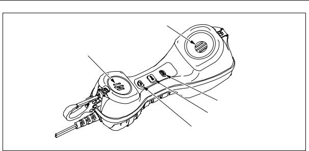
Housing
See Figure 1.
The TS52PRO Test Set housing is made of high-impact plastic. The test set provides rugged service and withstands the rough handling and shocks associated with field use. The housing permits operation in bad weather, such as heavy rain or dust storms.
Belt Clips
See Figure 1.
The belt clip can be located at either or both ends of the housing. It has a spring-loaded, locking clip that assures a secure connection to belt loops and D-rings. Both forward folding and backwards folding versions of the belt clip may be installed. The test set can be hung by the belt clip in one of two ways: (1) with keypad and speakerphone facing the user for convenient access or (2) with the transmitter facing the user.
The belt clips may be replaced or relocated in the field. See "Replacing or Relocating the Belt Clip" on page 21.
Keypad |
Display |
Speakerphone
microphone
Battery door
Speaker
Alternate belt clip
location
Line cord
strain relief Talk/Monitor switch
Belt clip
bfp01.eps
Figure 1. Physical Characteristics
3

TS52PRO Test Set
Users Guide
Line Cords
See Figure 1.
The test set has a field replaceable line cord. The line cord is attached through a rubber strain relief at the transmitter end of the test set. Line cords showing damage or abrasion should be replaced before using the instrument. See "Replacing the Line Cord" on page 21.
Several different configurations of line cords are available. See "Accessories (How to Order)" on page 23. for model numbers.
Battery
See Figure 1.
WWarningX
Use caution when handling batteries. Do not let the terminals short together. Dispose of batteries properly to ensure terminals cannot short. Disposal may be restricted by local laws.
Note
If the test set fails to operate properly, first replace the battery and retest before sending the test set in for repair.
A 9 V alkaline battery must be installed for the test set to operate. Do not use a rechargeable battery.
The battery:
If the test set stops working, remove the 9 V battery, wait at least 40 seconds, then replace the battery. This resets the test set. Use the same battery if you know it is good or use a new battery if you are not sure. If it still does not work, contact Fluke Networks Technical Support.
Speaker and Speakerphone Microphone
See Figure 1.
The speaker and speakerphone microphone are located on the keypad side of the test set. The speaker uses a lot of battery power. The battery lasts longer if the speaker is used in moderation.
Audio Controls
See Figure 2.
The three audio control keys are located on the inside handle of the test set between the handset receiver and the handset microphone. These controls let the operator switch between the handset and speakerphone, mute the active microphone, and control the volume of the received audio signal. Table 1 describes the audio control keys.
WWarning
Never hold the speaker against your ear when it is on, or when turning it on or off. Sounds emitted by the speaker can be loud enough to damage your hearing.
•Powers the test set when on-hook.
•It supplies supplementary current to the speaker (if on) when the test set is off-hook.
•Powers the display.
When the battery icon on the display shows no bars, the battery should be replaced immediately.
The test set’s battery compartment makes battery replacement easy. See "Replacing the Battery" on page 20 for instructions on changing the battery.
4
Physical Characteristics
Handset receiver
Handset microphone
Mute key
Speaker key
Volume key
bfp02.eps
Figure 2. Audio Control Keys
5
Loading...