

Page 1
injury and material damage. Read these instructions
thoroughly!
and comply with applicable safety directives when
working with hazardous or hot/cold medium.
is no risk of crush injuries. The risk is highest with
automatic valves.
unintentional manoeuvre - i.e to atmosphere.
ensuring that the line is free of pressure and any
content.
position to avoid trapping pressure and medium.
suitable for its intended use. This applies especially to
highly oxidising and corrosive medium. Observe also
the risk of erosion and explosion as well as decaying
medium. If in doubt, always request a written
recommendation from NAF AB.
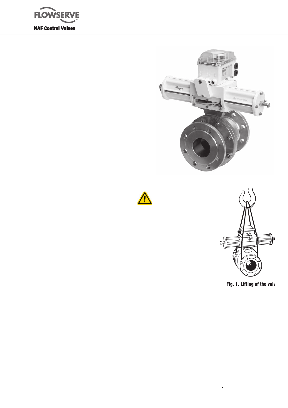
All lifting must be made in
the valve itself and not in the
the valve and the actuator
All valves leaving our works are inspected and tested
the pipework. However, in view of damage that may have
valve delivered is correct in
terms of type, size, equipment, etc
Page 2

the valve is to be installed are parallel and are correctly
valve must not be used for drawing together or aligning
as this will cause needless loads on
the valve and pipe which may lead to diffi cult damages
Wrong installation Correct installation
the pipework.
valve
Body EN 1.4408/CF8M
Body EN 1.4408/CF8M
Ball hard chrome EN 1.4408/CF8M/Hcr
Seat ring Alloy 6
Stem, assembly EN 1.4460
Circlip Spring steel
Backing ring PTFE
Upper lid EN 1.4436
Screw A4
Packing box PTFE/PTFE+25%C
Bushing PTFE+1.4401
Anti-friction washer EN 1.4436
Sealing ring PTFE
Screw A4-80
Nut A4
Screw A4-80
Key A4
Ball EN 1.4408/CF8M
Ball Alloy 6
Seatring EN 1.4436/PTFE+25%C
Bearing PTFE+1.4401
Trunnion plate EN 1.4470
Spring ASTM A316
Sealing ring PTFE+15%Graphite
O-ring FPM
Spring ASTM A316
Supporting ring Spring steel
Washer A4
Supporting ring PTFE
O-ring EPDM
Bushing PTFE reinforced carbon
Sliding washer PTFE reinforced carbon
Page 3
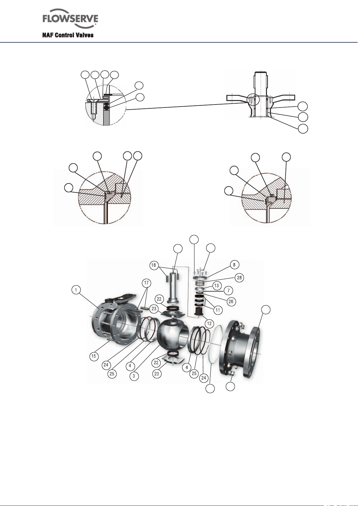
3
Alloy 6
with o-rings type 898X9X-XXXX
Page 4

Fk 41.66 and the manuf. No.specifi ed on the
identifi cation plate of the valve.
required - see table below.
Description Qty
6” 8” 10” 12” 16” 18” 20” 24” 28” 32
Wave spring
Page 5
isolate all electrical connections to the actuator.
cables connected to the actuator.
the pipework. Then lift out the valve. Don’t use
the actuator for lifting.
Apply all lifting forces to
the valve itself and not to the actuator
- Fig. 1.
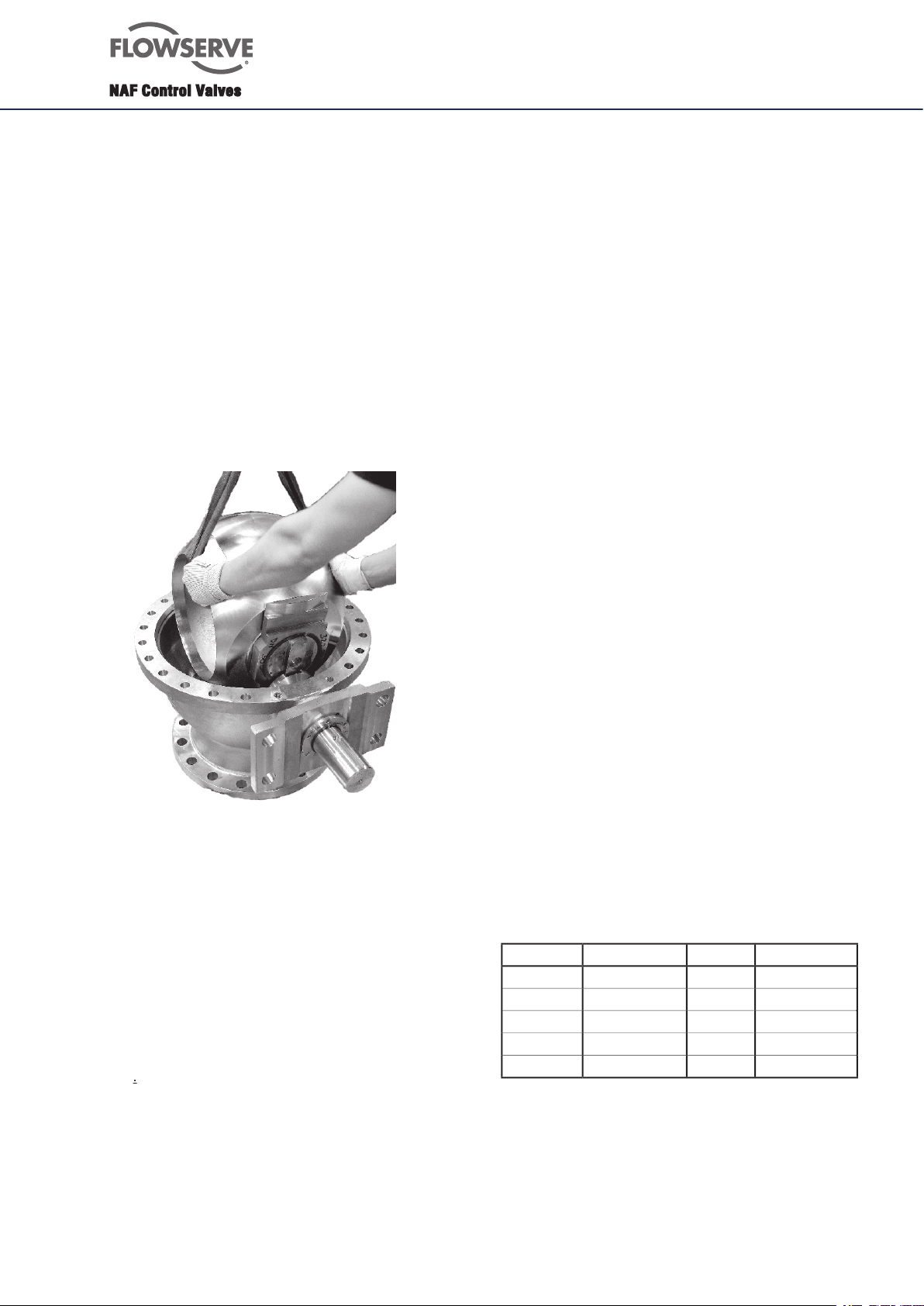
In certain applications, the pipe can be discon-
nected from one side of the valve, and the body
half (2) - Fig. 3 - can be removed, without the
need for removing the whole valve from the
pipework.
by centre-punching before the dismounting
since the pattern of the holes drilled in the valve
fl ange and pipe fl ange may vary.
tion - here with the valve on a work bench.
It can also be done with mounted actuator
and the body (1) mounted in the pipework.
gaskets for the pipe fl anges are available.
Before dismounting the valve,
it is completely empty
times between the open and closed positions to
ensure that the space between the valve body and
ball is not under pressure.
for
replacing the seatring and ball.
completely empty
do when the valve is in closed position.
bearing from the bearing journal of the ball.
if necessary, some degreasing compound. Do not
scrape any machined surfaces with hard tools.
seatrings, wave springs and sealings if they are worn
or damaged.
25) behind the seatring (pos 20).
can be removed by polishing with fi ne emery cloth. If
the ball has major damages, it must be replaced to
ensure satisfactory tightness.
halves.
ball.
for service in an oxygen system, the ball can be coa-
ted with silicone grease, which is approved for oxygen
applications.
i.e. Crane Packings’s Thread-Grade or Gleitmo 600.
(1) and then the upper bodyhalf (2). Make sure that
the centrepunch marks made according to section 8.1
item 6 are lined up. Tighten the bolted joint of the two
bodyhalves alternately in several stages and tighten
them fi nally as per the table below.
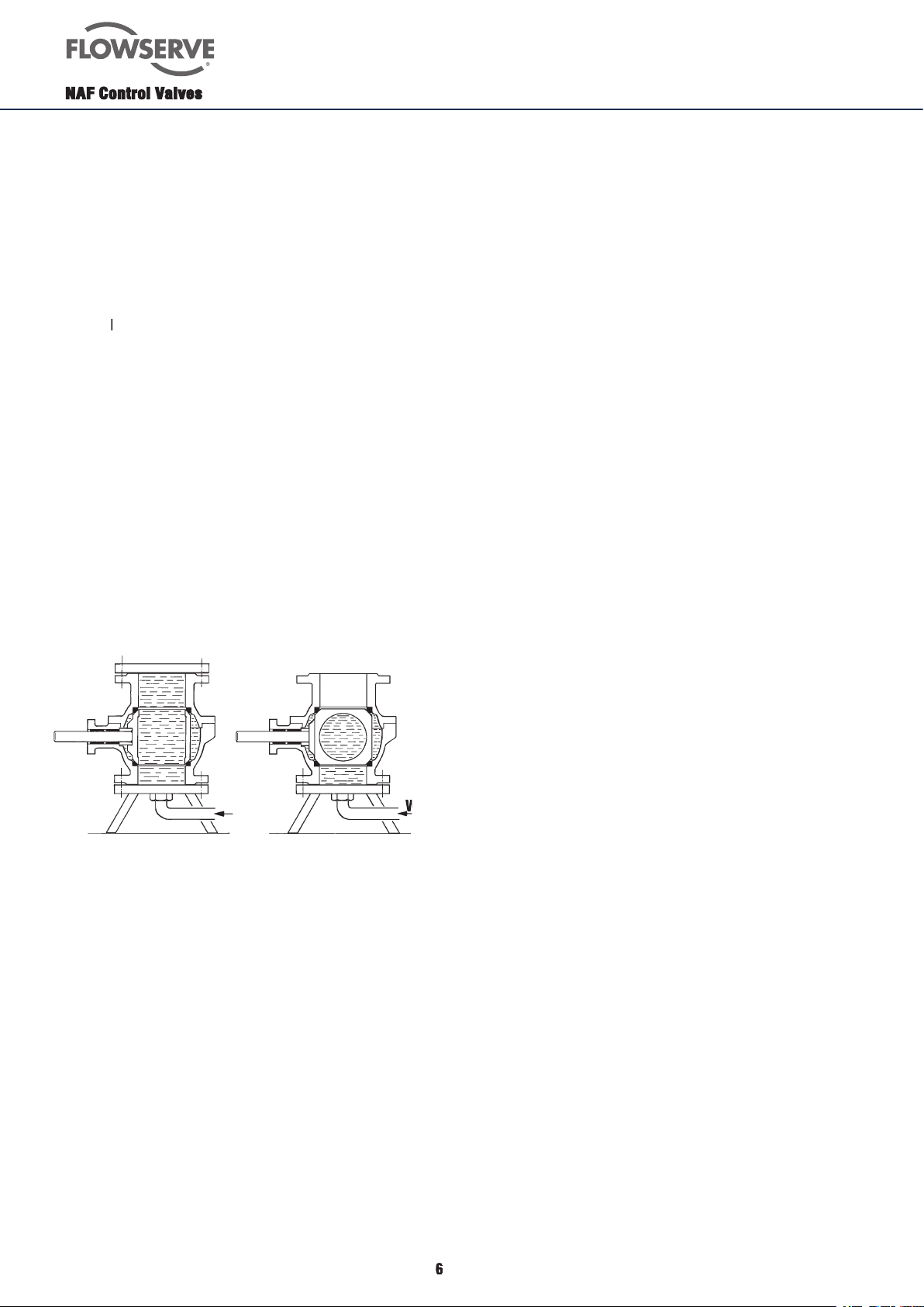
its tightness - Fig. 5.
valve are properly fi lled
with water before the pressure
testing. The valve should be pressure tested as follows:
Open valve: PN x 1,5
Closed valve: Max dp x 1,1
Page 6
in alloy 6
A groove on the inside of the ring facilitates with-
drawal. Minor damage to the rings can be polished
with fi ne emery cloth. Check the rings on a face
plate to ensure that they are perfectly fl at. Do
not lap the rings and the chromium-plated ball
together. Change the rings if they are severely
damaged.
damage may be polished with fi ne emery cloth.
If the existing ball must be used for a further
period of time, remove all sharp edges, dents and
irregularities with a fi ne fi le or emery cloth. Check
the circularity of the ball. The tolerance is
If the ball is seriously damaged, it must be
replaced.
and 25) behind the seatring.
bodyhalves.
Molykote U.
section 8.3
Valve open Valve closed
Water
valves with packing box type PSDCL
(DN150-DN400) i.e. type
8982EF-XXXX-BABADA
from the underside of the mounting plate of the
valve keeps the actuator in place.
keys.
and remove the upper lid (8). Note! The upper
lid is prespringloaded.
it.
ring (7), o-ring (26) and packing box (11).
the body.
through the body.
grease before you press it down into the body.
Note that the broadest of the 5 rings should be
on top, see fi g 3 on page 3.
the body and out.
washer (13), lubricate a new o-ring (26) with
silicone grease and mount it in the anti-friction
washer. Mount the anti-friction washer with the
o-ring downwards against the valve.
item 5 to 1.
those in section 8.4 above.
mend that the valve is returned to NAF for repair.
This applies especially if the ball must be ground
before lapping. Assemble the valve before dispat-
ching it to NAF.
ted by lapping them together. This can be done
manually with a compound with grit size 200. Take
great care to ensure that the ball and seat rings do
not become oval.
lubricated before they are mounte
solvent for cleaning. Then lubricate the ball with
silicone grease, such as Molykote Dow Corning
FS3452. The coat of grease must be very thin.
Then polish the ball with chamois leather or a
piece of soft cloth.
Water
Page 7
(DN450-DN800) i.e. type 898295-XXXX
from the underside of the mountingplate of the
valve keeps the actuator in place.
keys.
(29).
(30) and the anti-friction washer in PTFE (31).
the new ring with silicone grease before it is
mounted.
(
8.7, item 1 and 2.
(30) and the anti-friction washer of PTFE (31).
it.
intermediate o-ring (32).
been lubricated with Silicone grease. Change
also the sliding washer (34) on the stem.
reverse order.
Before that consider to change the seatrings or
lapping of the seatrings and ball.
the bolts according to section 8.3.
either in line with the connected pipes or transversely
to them. For mounting in line with the connected
pipes an intermediary plate is required
the closed position before mounting the actuator.
The valve is in the closed position when the
keyway on the stem is in the direction of fl ow.
(An actuator which uses compressed air to close
the valve and a return spring to open the valve
should be mounted with the actuator and valve in the
open position.)
The direction of closure must always be
clockwise, as viewed from the actuator.
actuator slides easily onto the stem when the
keys are not fi tted. Check also that the keys fi t
freely into the keyways in the hollow shaft of the
actuator. Deburr if necessary. Lubricate the hollow
shaft of the actuator and push it in over the
threaded sleeve. Mount the actuator onto the stem.
Mount the bolts and nuts, and tighten them.
have been correctly preset. If necessary, make
adjustments.
If any accessories such as valve positioner or
limit switches should be mounted, please see the
corresponding manufacturer’s instructions for
installation and adjustment.
Page 8

 Loading...