

Page 1

TRS 5-8
Installation Instructions 810709-01
Temperature Switch TRS 5-8
1
Page 2

Contents
Page
Important Notes
Usage for the intended purpose ...................................................................................... 7
Safety note ......................................................................................................................7
Danger ............................................................................................................................ 7
Explanatory Notes
Scope of supply ..............................................................................................................8
Description ......................................................................................................................8
Function .......................................................................................................................... 8
Design .............................................................................................................................8
Technical Data.................................................................................................................9
Installation
TRS 5-8b ...................................................................................................................... 10
Examples of installation ................................................................................................ 15
Wiring
TRS 5-8b ...................................................................................................................... 11
Setting temperature limit
Example 1 .....................................................................................................................12
Example 2 .....................................................................................................................12
Example 3 .....................................................................................................................12
Commissioning
Check wiring..................................................................................................................12
Apply mains voltage ......................................................................................................12
Performance test ...........................................................................................................13
Annex
Danger ..........................................................................................................................13
Fault finding list .............................................................................................................13
Declaration of conformity .............................................................................................. 14
2
Page 3
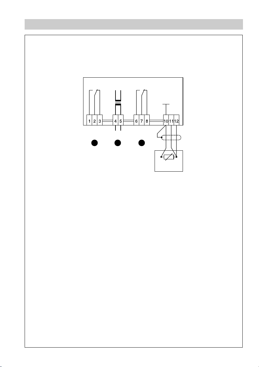
Wiring Diagram
TRS 5-8 b
°C
MAX
6 8
L N
7
Fig. 1
°C
MIN
Pt 100
DIN IEC 751
TRG 5-53
TRG 5-54
TRG 5-55
TRG 5-56
TRG 5-57
TRG 5-58
3
Page 4
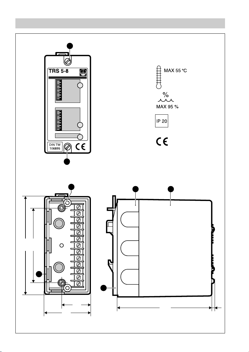
Parts Drawings
2
4
8
16
32
64
128
256
2
4
8
16
32
64
128
256
°C
°C
A
MAX
MIN
Fig. 2
A
B
85
112
C
F
32
51
Fig. 3 Fig. 4
107
ED
3
4
Page 5
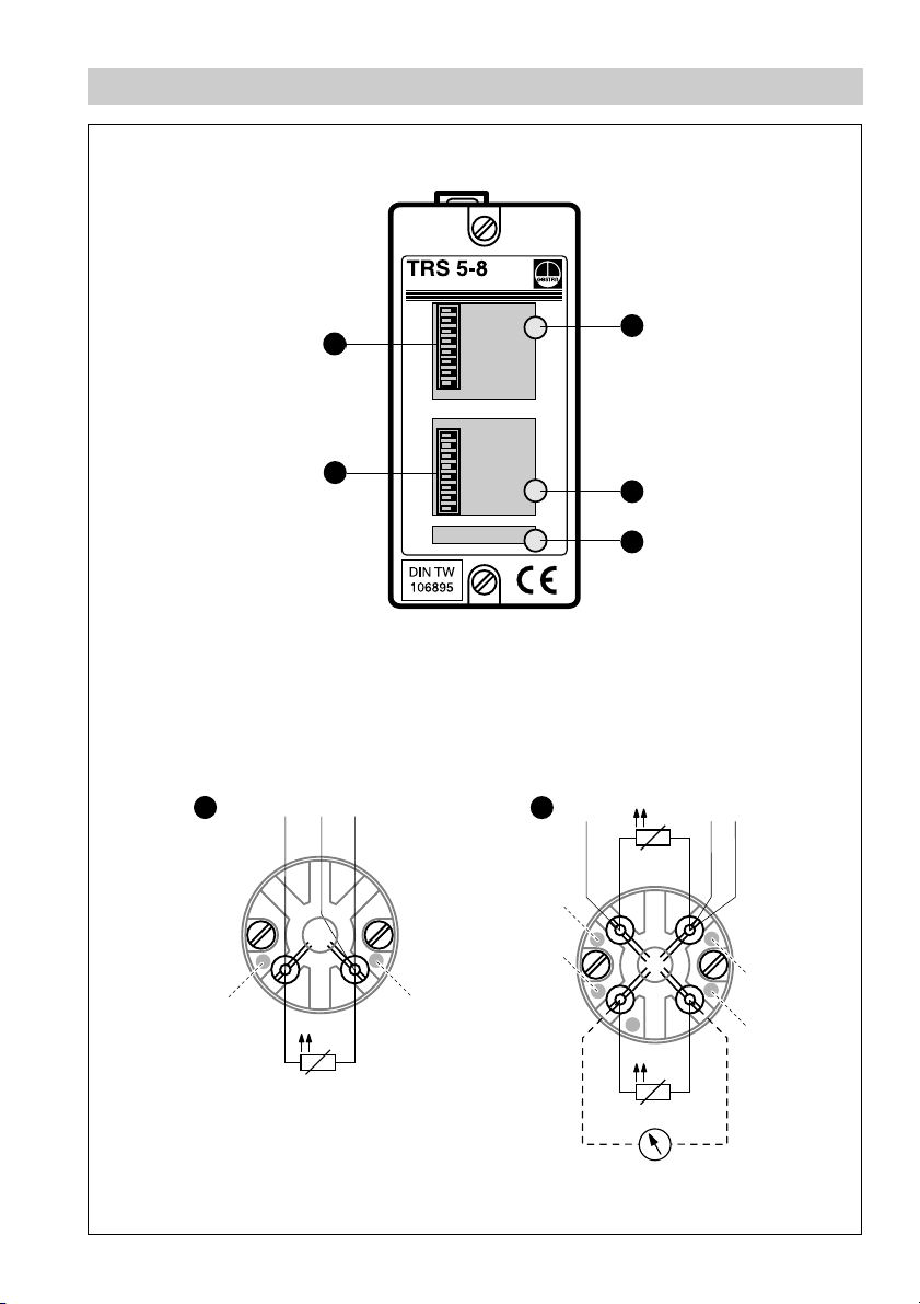
Parts Drawings
Fig. 5
2
4
°C
8
MAX
5
4
16
32
64
128
256
2
4
8
16
32
64
°C
MIN
128
256
1
2
3
G
red
Fig. 6
10 12
11
ϑ
white
10 1211
H
yellow
red
Fig. 7
ϑ
black
white
ϑ
5
Page 6

Key
A
Cover screw
B
Hole for wall mounting
C
Cable entry
D
Base
E
Cover
F
Mounting clip
G
Resistance thermometer TRG 5-53, TRG 5-55, TRG 5-57 (1 x Pt 100)
Resistance thermometer TRG 5-54, TRG 5-56, TRG 5-58 (2 x Pt 100)
H
1
LED “High temperature limit”
2
LED “Low temperature limit”
3
LED “Operation”
4
Code switch for low temperature setting
5
Code switch for high temperature setting
6
Switching relay for high temperature
7
Mains
8
Switching relay for low temperature
6
Page 7

Important Notes
Usage for the intended purpose
The temperature switch TRS 5-8 must only be used in conjunction with resistance
thermometers TRG 5-53, TRG 5-54, TRG 5-55, TRG 5-56, TRG 5-57 and TRG 5-58
for monitoring and signalling temperature limits.
Safety Note
The equipment must only be installed by qualified staff.
Qualified staff are those persons who – through adequate training in electrical
engineering, the use and application of safety equipment in accordance with
regulations concerning electrical safety systems, and first aid & accident
prevention – have achieved a recognised level of competence appropriate to the
installation and commissioning of this device.
Danger
The terminal strip of the TRS 5-8 b is live during operation. This presents
the danger of electric shock. Cut off power supply before installing or
removing the cover.
7
Page 8

Explanatory Notes
Scope of supply
TRS 5-8 b
1 Temperature switch (plug-in unit in plastic case for installation in control
cabinets)
1 Installation manual
Description
MAX/MIN temperature switch TRS 5-8 used in conjunction with resistance
The
thermometer TRG 5-53, TRG 5-54, TRG 5-55, TRG 5-56, TRG 5-57, TRG 5-58 is a
temperature controller in accordance with DIN 3440.
When the actual value exceeds the adjusted limit the equipment will trigger an alarm.
Application in steam boilers, pressurized hot-water plants operating without constant
supervision (TRD 604) as well as any other kind of heat generating unit.
Function
The temperature switch TRS 5-8 is a two-channel temperature monitoring system
used in conjunction with a standardized platinum resistance thermometer Pt 100 in
accordance with DIN IEC 751. A power source fitted with a variable resistor supplies
the resistance thermometer with a constant current. The desired cut-off
temperatures are adjusted by means of an eight-pole code switch. To ensure a failsafe alarm signal as soon as the temperature exceeds the max. limit the output
contact relays of the TRS 5-8 are of the normally closed type.
In the event of a power supply failure the temperature switch will signal an alarm
condition.
The temperature switch is designed for two operating conditions:
■ Normal operation (temperature within admissible range)
■ Alarm (temperature above/below limit)
The green LED indicates power supply. The two red LEDs indicate alarm when the
temperature exceeds the adjusted limit.
Design
TRS 5-8b:
Plug-in unit in plastic case for snapping onto the supporting rail TS 35 x 15 to DIN
EN 50022 for installation in control cabinets.
8
Page 9

Explanatory Notes – continued –
Technical Data
Type approval no.
DIN TW 1068 2000
Input
Connection for resistance thermometer Pt 100:
TRG 5-5..., PN 40-160, T
Output
Two volt-free relay contacts. Max. contact rating with switching voltages of 24 V,
115 V and 230 V a. c.: 4 A resistive, 0.75 A inductive, cos
Max. contact rating with a switching voltage of 24 V d. c.: 4 A
Contact material: silver, hard-gold plated.
Temperature limit range
Code-switch selectable in steps of 2°C within a range of 30°C to 540°C.
Switching hysteresis
At
MAX limit: –5 °C
At
MIN limit: 5°C
Indicators and adjustors
Two LEDs “Alarm”, one LED “Power supply”,
one code switch for “
MIN temperature”, one code switch for “MAX temperature”.
Mains supply
230 V +/– 10 %, 50/60 Hz.
Special voltage 115 V +/– 10 %, 50/60 Hz or 24 V +/– 10 %, 50/60 Hz.
251°C – 540°C
max
ϕ 0.5.
Power consumption
5 VA
Protection
TRS 5-8 b:
IP 20 to DIN EN 60529
Admissible ambient temperature
0 °C to 55 °C
Case materials
TRS 5-8b:
Base: ABS plastic, black
Cover: polystyrene, highly shock resistant, stone grey, Fig. 3, Fig. 4
Weight
approx. 0.6 kg
9
Page 10

Installation
TRS 5-8b
On supporting rail (with mounting clip)
1. Clip temperature switch onto supporting rail.
2. Loosen cover screws and unplug cover from its base .
3. Select cable entry and remove corresponding seal.
C
On mounting panel
1. Loosen cover screws and unplug cover from its base .
2. Unscrew mounting clip .
3. Drill the hole marked in the base to 4.3 mm dia.
B
A E D
F
4. Fasten base with two M4 screws onto mounting panel.
Tool
■
Screwdriver (5.5/100)
E DA
10
Page 11

Wiring
TRS 5-8 b
Use screened four-core supply cable for wiring, e. g. 2 x 2 x 0.8 mm or 4 x 0.5 mm
1. Connect terminal strip according to wiring diagram. Fig. 1
2. Connect additional display units to terminals marked in yellow and black of the
TRG 5-54, TRG 5-56 and TRG 5-58. Fig. 7
Wiring Diagram
See wiring diagram page 2.
Attention
■
To protect the switching contacts fuse circuit with T 2.5 A or according
to TRD regulations (1.0 A for 72 h operation).
■
The screen must not make any other electrical contact.
Note
■
Connect screen only to terminal [10] of the temperature switch.
■
The loop resistance must be lower than 10 Ω.
■
The rated voltage is stated on the name plate.
■
When switching off inductive loads, voltage spikes are produced that
may impair the operation of control and measuring systems. Inductive
loads should therefore be provided with commercial arc suppressor
RC combinations, e. g. 0.1 µF/100 Ω.
2
.
Tool
■
Screwdriver for slotted screws, size 2.5, completely insulated according to
VDE 0680.
11
Page 12

Adjust MAX/MIN Temperature Limits
Use the two code switches at the rear of the TRS 5-8 to adjust the temperature limits,
Fig. 5.
Example 1
Requested temperature limit τ
= 176°C. The 8-pole code switch shows values
max
between “2” and “256”. The basic temperature is 30 °C. Set the “2”, “16” and “128”
switches to the left using a small screwdriver. The sum of the three values gives a
temperature of 146 °C, plus the basic temperature of 30°C. This corresponds to the
requested temperature limit τ
= 176°C.
max
Example 2
Requested temperature limit τ
= 446 °C. Set the “32”, “128” and “256” switches to
max
the left using a small screwdriver. The sum of the three values gives a temperature
of 416°C, plus the basic temperature of 30°C. This corresponds to the requested
limit temperature τ
= 446 °C.
max
Example 3
Requested temperature limit τ
= 79°C. Set the “16” and “32” switches to the left
min
using a small screwdriver. The sum of the two values gives a temperature of 48°C,
plus the basic temperature of 30°C. This corresponds to a limit temperature τ
min
=
78°C. An adjustment of exactly 79 °C is not possible as temperatures can only be
adjusted in steps of 2°C.
Tool
■
Screwdriver for slotted screws, size 2.5, completely insulated according to
VDE 0680.
Commissioning
Check wiring
Check whether the TRS 5-8 has been wired to its associated system components
TRG 5-... according to the wiring diagram. Fig. 1, Fig. 6 or Fig. 7.
Apply mains voltage
Switch on mains voltage. The green LED will be illuminated. Fig. 5
12
3
Page 13

Commissioning – continued –
Check functions
TRS 5-8 b
1. When switching on the mains voltage the green LED should be permantently
illuminated. Fig. 3
2. Raise temperature in heat generator until the permissible temperature limit is
exceeded. The red LED on the temperature switch must light up.
3. After lowering the temperature the red LED must extinguish.
1
1
4. Lower the temperature until it falls below the min. temperature limit.
The red LED on the temperature switch must light up.
5. After raising the temperature the red LED must extinguish.
2
2
3
Annex
Warning
The terminal strip of the TRS 5-8b is live during operation. This presents
the danger of electric shock. Cut off power supply before fixing or removing
the cover.
Fault finding list
Fault:
Remedy:
Remedy:
Remedy:
The temperature switch signals alarm during normal operation.
Check whether the green LED is illuminated. If not, check power supply.
3
Check whether resistance thermometer supply cable is damaged.
Check whether measured values emitted by resistance thermometer
are correct (basic values of measuring resistors in accordance with
DIN 43760 for Pt 100).
If faults occur that are not listed above please contact our subsidiary or agency
in your country.
13
Page 14

Annex – continued –
Declaration of Conformity
We hereby declare that the equipment TRS 5-8 b conforms to the following
European guidelines:
■
LVD 73/23/eec version 93/68/eec
■
EMC guideline 89/336/eec version 93/68/eec
which are based on the following harmonised standards:
■
LV standard EN 50 178
■
EMC standard DIN EN 61000-6-4, EN 50 082-2
This declaration is no longer valid if modifications are made to the equipment
without consultation with us.
Bremen, 15
GESTRA GmbH
Dr. Anno Krautwald
Key
A
Cover screw
Hole for wall mounting
B
Cable entry
C
D
Base
E
Cover
F
Fixing clip
I
Mounting rail TS 35 x 15 to DIN EN 50022
th
July 1997
Dr. Christian Politt
14
Page 15

Example of Installation
E
2
4
8
°
C
MAX
16
32
64
128
256
2
4
8
16
32
64
°
C
MIN
128
256
F D
C
I
Fig. 8
Fig. 9
A
B
B
15
Page 16

GESTRA Gesellschaften · GESTRA Companies · Sociétés GESTRA · Sociedades Gestra · Società GESTRA
Vertretungen weltweit · Agencies all over the world · Représentations dans le monde entier · Representaciones en todo el mundo · Agenzie in tutto il mondo
España
GESTRA ESPAÑOLA S.A.
Luis Cabrera, 86-88
E-28002 Madrid
Tel. 00 3491/5 152032
Fax003491/4136747; 5152036
E-mail: gestra@gestra.es
Polska
GESTRA POLONIA Spolka z o.o.
Ul. Schuberta 104, P. O. Box 71
PL-80-172 Gdansk
Tel. 004858 / 306 10 02 oder 306 10 10
Fax 00 48 58 / 3061003 oder 3063300
E-mail: gestra@gestra.pl
France Portugal
Flowserve Flow Control S. A.S.
10 Avenue du Centaure, BP 8263
F-95801 CERGY PONTOISE CEDEX
Tél. 003 31 / 3443 26 60
Fax00331/34432687
E-mail: gnation@flowserve.com
Flowserve Portuguesa, Lda.
Av. Dr. Antunes Guimarães, 1159
Porto 4100-082
Tel. 0035122/6198770
Fax 00351 22/6107575
E-mail: gestra@gestra.pt
Italia
Italgestra S.r.l.
Via Carducci 125
l-20099 Sesto San Giovanni (MI)
Tel. 00 39 02 / 2410 12.1
Fax 0039 02/ 2410 12.460
E-mail: info@italgestra.it
®
GESTRA GmbH
Postfach 10 54 60
D-28054 Bremen
Münchener Str. 77
D-28215 Bremen
Tel. +49 (0) 421 35 03- 0
Fax +49 (0) 421 35 03- 393
E-mail
gestra.gmbh@flowserve.com
Internet www.gestra.de
A Unit of Flowserve Corporation
810709-01/1202c · © 1997 GESTRA GmbH · Bremen · Printed in Germany
16
 Loading...