

Page 1

TRS 5-6
Installation Instructions 810378-03
Temperature Switch Type TRS 5-6
1
Page 2

Contents
Page
Important Notes
Usage for the intended purpose ...................................................................................... 7
Safety note ......................................................................................................................7
Danger ............................................................................................................................ 7
Explanatory Notes
Scope of supply ..............................................................................................................7
System description .......................................................................................................... 8
Function .......................................................................................................................... 8
Technical Data ................................................................................................................. 9
Installation
TRS 5-6b ...................................................................................................................... 10
TRS 5-6c/d ...................................................................................................................10
Example of installation ..................................................................................................15
Wiring
TRS 5-6b, TRS 5-6c/d ..................................................................................................11
Adjusting Temperature Limit
Example 1 .....................................................................................................................12
Example 2 .....................................................................................................................12
Example 3 .....................................................................................................................12
Commissioning
Check wiring..................................................................................................................12
Apply mains voltage ......................................................................................................12
Check functions.............................................................................................................13
Annex
Fault finding list for troubleshooting ...............................................................................13
Declaration of conformity .............................................................................................. 15
2
Page 3
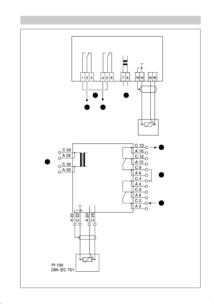
Wiring Diagram
L
10
N
Fig. 1
TRS 5-6c/d
TRS 5-6b
8
99
L N
10
Pt 100
DIN IEC 751
9
8
Fig. 2
9
3
Page 4
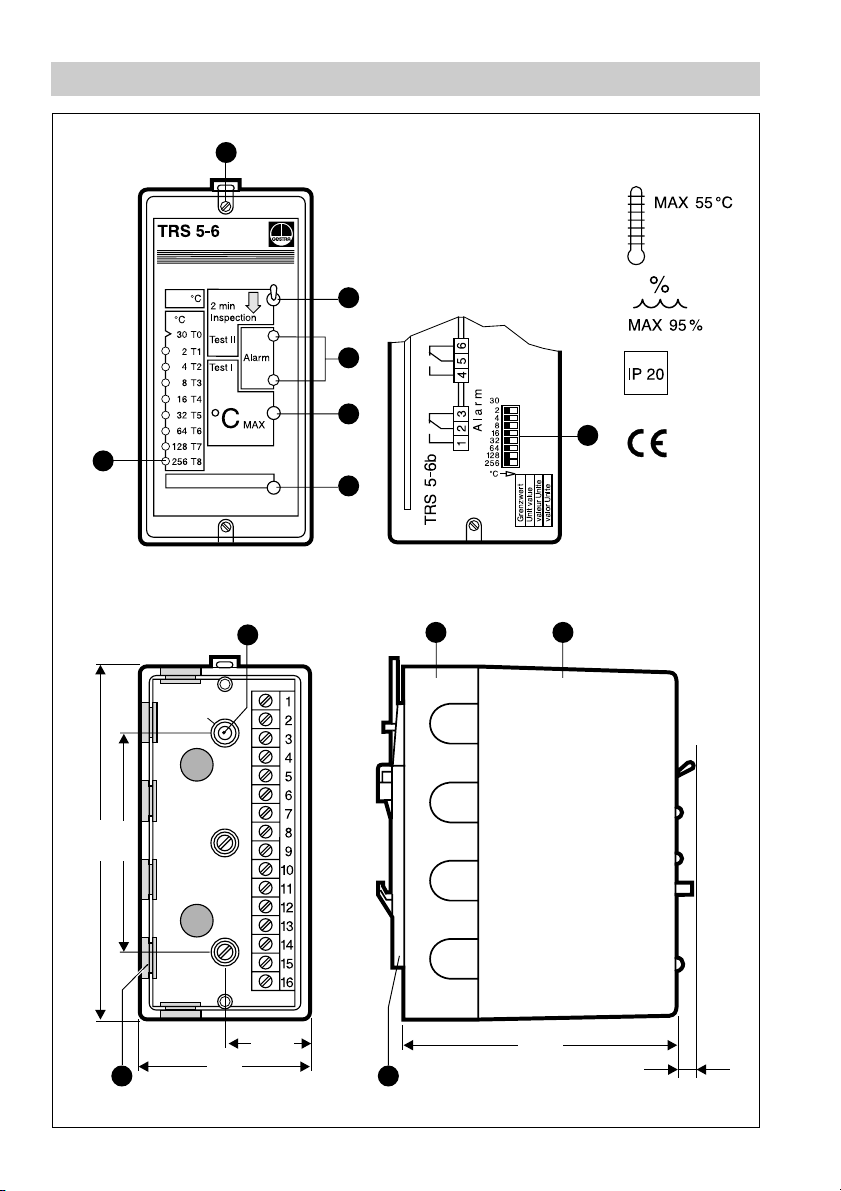
Parts Drawings
A
5
Fig. 3 Fig. 4
1
2
3
6
4
D E
F
120
5
158
C
B
95
37.5
75
Fig. 5 Fig. 6
4
Page 5
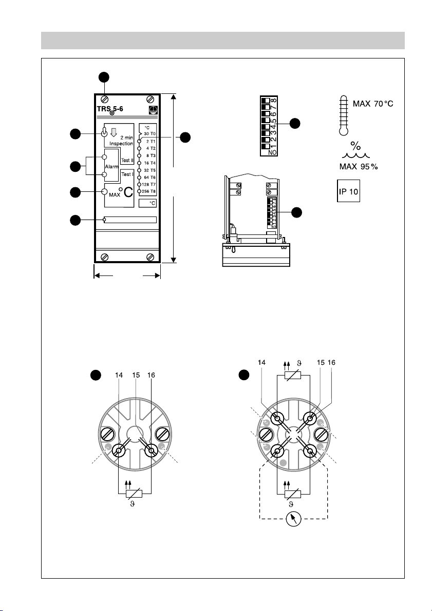
Parts Drawings
G
1
2
30
2
4
8
16
32
5
128
256
64
°C
7
3
4
12 TE
128.5
1 TE (= division units)
^
5.08 mm
=
7
Fig. 8Fig. 7
I
yellow
red
black
white
red
H
white
Fig. 10Fig. 9
5
Page 6

Key
A
Cover screw
B
Hole for wall mounting
C
Cable entry
D
Base
E
Cover
F
Mounting clip
G
Fixing screws for 19" slide-in unit
H
Resistance thermometer TRG 5-53, TRG 5-55, TRG 5-57 (1 xPt 100)
I
Resistance thermometer TRG 5-54, TRG 5-56, TRG 5-58 (2 xPt 100)
1
Toggle switch
2
LED ALARM
3
Button TEST 1
4
LED
POWER
TEST 2/ INSPECTION
5
LED TEMPERATURE COEFFICIENT
6
Code switch TRS 5-6 b
7
Code switch TRS 5-6 c / d (19" slide-in unit)
8
External wire link
9
Protection circuit
10
Mains
6
Page 7

Important Notes
Usage for the intended purpose
Temperature switch type TRS 5-6 serves as safety device in plants requiring official
approval and is used in conjunction with resistance thermometers types TRG 5-53,
TRG 5-54, TRG 5-55, TRG 5-56, TRG 5-57 and TRG 5-58. Use temperature switch
only for signalling temperature limits.
Safety note
Use temperature switch TRS 5-6b, TRS 5-6 c/d only for signalling temperature limits.
The equipment must only be installed by qualified staff.
Qualified staff are those persons who – through adequate training in electrical
engineering, the use and application of safety equipment in accordance with
regulations concerning electrical safety systems, and first aid & accident
prevention – have achieved a recognised level of competence appropriate
to the installation and commissioning of this device.
Danger
The terminal strip of the TRS 5-6 b, TRS 5-6 c/d is live during operation.
This presents the danger of electric shock. Cut off power supply before
fixing or removing the cover.
Explanatory Notes
Scope of supply
TRS 5-6b
1 Temperature switch (plug-in unit in plastic case for installation in control cabinets)
1 Installation manual
TRS 5-6c
1 Temperature switch (19" slide-in unit, front panel acc. to DIN 41494, part 5, 12 TE
2 Guide rails
1 Screw-type connector
1 Installation manual
TRS 5-6d
1 Temperature switch (19" slide-in unit, front panel acc. to DIN 41494, part 5, 12 TE
1 Installation manual
1
) TE = division units (1 TE = 5.08 mm)
1
)
1
)
7
Page 8

Explanatory Notes – continued –
System description
Self-monitoring temperature switch with periodic self-checking feature to be used in
conjunction with a resistance thermometer type TRG 5-53, TRG 5-54, TRG 5-55,
TRG 5-56, TRG 5-57 or TRG 5-58.
The equipment operates as a safety temperature controller, or in conjunction with an
external lock-out in accordance with VDE 0116 as a safety temperature limiter.
An alarm is given as soon as the temperature exceeds a preset limit value.
Application in steam boilers and pressurized hot-water plants operating without
constant supervision (TRD 604) as well as any other kind of heat generator.
Function
The temperature switch type TRS 5-6 is a two channel unit provided with an
automatic periodic self-checking logic unit, in accordance with DIN 3440/VDE 0116
(regulations for protection circuits for firing equipment of furnaces). The two
channels are designed to monitor the operation of each other. If one channel fails,
an alarm signal is initiated, simultaneously switching the output contacts to shut off
the heat supply. The periodic self-checking logic unit checks the two channel
circuits for malfunction. The integrity of the resistance thermometer is continuously
monitored by the TRS 5-6. This is done automatically every 40 seconds by the
triggering of a test alarm pulse through the circuit. Unless it finds a fault, this
internal test does not interfere with the output contacts of the temperature switch
and therefore the plant operation is not interrupted.
A manual test push button is also provided. When the push button
it simulates a fault in the resistance thermometer. There is also a toggle switch
TEST II / INSPECTION for checking the function of the self-checking circuitry.
The output contact relays of the temperature switch are of the normally closed type
and will therefore signal alarm condition in the event of a mains failure.
The temperature switch can signal the following three operating conditions:
■
Normal operation (temperature within permissible range)
■
Alarm (limit temperature exceeded)
■
Alarm (fault in temperature switch or resistance thermometer)
A green LED indicates mains supply
ON. Exceeding of limit temperature or
malfunction of the system is indicated by two red LEDs. The failure of one channel
(loss of redundancy) is signalled by the lighting-up of one red LED.
The combination of resistance thermometer TRG 5-... and temperature switch
TRS 5-6 provides fail-safe protection against a first fault, i. e. the system will still
continue to provide the safety function even after the occurence of a first fault.
TEST I is pressed,
8
Page 9

Explanatory Notes – continued –
Technical Data
Type-approval no.
DIN · STW (STB) · 985 93S
Input
3 terminals for the connection of one resistance thermometer (Pt 100):
TRG 5-5..., PN 40– 160, T
Output
2 volt-free relay contacts.
Max. contact rating with switching voltages of 24 V, 115 V and 230 V a. c.:
4 A resistive, 0.75A inductive, cos ϕ 0.5.
Max. contact rating with a switching voltage of 24 Vd.c.: 4A
Contact material silver, hard-gold plated.
Temperature range
Temperature limits adjustable in steps of 2°C within a range of 30 °C to 540 °C by a
code switch.
Switching hysteresis
–3°C
Indicators and adjustors
2 red LEDs
ALARM
1 green LED “POWER ON”
1 button
1 toggle switch
TEST I
TEST II / INSPECTION
8 LEDs and 1 eight-pole code switch for setting the limit temperature.
Mains supply
230V +/– 10%, 50/60 Hz
Special voltage: 115 V +/– 10 %, 50/60 Hz or 24V +/– 10%, 50/60 Hz
Power consumption
5 VA
Protection
TRS 5-6 b: IP 20 to DIN EN 60 529
TRS 5-6 c: IP 10
TRS 5-6 d: IP 10
Permissible ambient temperature
TRS 5-6b: 0 –55 °C
TRS 5-6c: 0– 70°C
TRS 5-6d: 0 –70 °C
Case materials
TRS 5-6b: Base: ABS plastic, black. Cover: polystyrene, highly shock-resistant,
stone grey. Fig. 5, Fig. 6
TRS 5-6c: Front panel: Aluminium. Fig. 7
TRS 5-6d: Front panel: Aluminium. Fig. 7
Weight
TRS 5-6b: approx. 1.0 kg
TRS 5-6c: approx. 0.8 kg
TRS 5-6d: approx. 0.8 kg
251°C–540°C
max
9
Page 10

Installation
TRS 5-6b
On supporting rail (with mounting clip)
1. Clip temperature switch onto supporting rail.
2. Loosen cover screws and unplug cover from its base .
3. Select cable entry and remove corresponding seal.
C
EA
On mounting panel
1. Loosen cover screws and unplug cover from its base .
2. Unscrew mounting clip .
3. Drill the hole marked in the base to 4.3 mm dia.
B
A E D
F
4. Fasten base with two M4 screws onto mounting panel.
TRS 5-6c
1. Mount plastic card guide rail into 19" magazine.
2. Install screw-type connector.
3. Introduce 19" slide-in unit into magazine and fix with screws .
TRS 5-6d
1. Mount plastic card guide rail into 19" magazine.
2. Install screw-type connector.
3. Introduce 19" slide-in unit into magazine and fix with screws .
D
G
G
Tools
■
Screwdriver (5.5/100)
10
Page 11

Wiring
TRS 5-6 b
Use screened four-core supply cable for wiring, e.g. 2x2x0.8 mm or 4x 0.5 mm²
1. Connect terminal strip according to wiring diagram. Fig. 1
2. Connect additional display units to terminals marked in yellow and black of the
TRG 5-54, TRG 5-56 and TRG 5-58. Fig. 10
TRS 5-6 c/d
Use screened four-core supply cable for wiring, e.g. 2x2x0.8 mm or 4x 0.5 mm².
The external wire link should be fitted on site.
1. Connect terminal strip according to wiring diagram. Fig. 2
2. Connect additional display units to terminals marked in yellow and black of the
TRG 5-54, TRG 5-56 and TRG 5-58. Fig. 10
Wiring diagram
See wiring diagram on page 3.
Attention
■
To protect the switching contacts fuse circuit with T 2.5A or
according to TRD regulations (1.0A for 72h operation).
■
The screen must not make any other electrical contact.
Note
8
■
Connect screen only to terminal [13] of the temperature switch
TRS 5-6 b or [A22] of the temperature switch TRS 5-6c/d.
■
The loop resistance must be under 10 Ω.
■
The rated voltage is stated on the name plate.
■
When switching off inductive loads, voltage spikes are produced
that may impair the operation of control and measuring systems.
Inductive loads should therefore be provided with commercial
arc suppressor RC combinations, e.g. 0.1 µF/100 Ω.
Tool
■
Screwdriver for slotted screws, size 2.5, completely insulated according to
VDE 0680.
11
Page 12

Adjusting Temperature Limit
On the rear of the TRS 5-6 there is a code switch for adjusting the temperature.
Example 1
Requested temperature limit τ
=176 °C. The 8-pole code switch shows values
max
between “2” and “256”. The basic temperature is 30 °C. Set the “2”, “16” and “128”
switches to the right using a small screwdriver. The other switches remain in their
left hand position. The sum of the three values gives a temperature of 146°C, plus
the basic temperature of 30°C. This corresponds to the requested temperature limit
τ
=176 °C.
max
Example 2
Requested temperature limit τ
=446 °C. Set the “32”, “128” and “256” switches to
max
the right using a small screwdriver. The sum of the three values gives a temperature
of 416 °C, plus the basic temperature of 30°C. This corresponds to the requested
limit temperature τ
= 446 °C.
max
Example 3
Requested temperature limit τ
=79 °C. Set the “16” and “32” switches to the right
max
using a small screwdriver. The sum of the two values gives a temperature of 46 °C,
plus the basic temperature of 30°C. This corresponds to a limit temperature
τ
=78 °C. An adjustment of 79 °C is not possible as temperatures can only be
max
adjusted in steps of 2 °C.
Tool
■
Screwdriver for slotted screws, size 2.5, completely insulated according to
VDE 0680.
Commissioning
Check wiring
Check whether the TRS 5-6 has been wired to its associated system components
TRG 5-... according to the wiring diagram. Fig. 1, Fig. 2, Fig. 9, Fig. 10
Apply mains voltage
Switch on power supply. The LED will be illuminated. Fig. 3, Fig. 7
12
4
Page 13
Commissioning – continued –
Check functions
TRS 5-6 b, TRS 5-6 c/d
1. When switching on the mains voltage the green LED should be permantently
illuminated. Fig. 3
2. Raise temperature in heat generator until the permissible temperature limit is
exceeded. The two red LEDs on the temperature switch must light up.
2
3. After lowering the temperature the two red LEDs must extinguish.
4. An alarm ‘limit temperature exceeded’ can be simulated by pushing the button
3
TEST I . On pushing the button the two red LEDs must light up.
5. To check the function of the self-checking circuitry of the temperature switch
proceed as follows: Set switch
After max. two minutes the two red LEDs should signal alarm. The button
3
TEST I must not be operated during this test nor must the adjusted limit
TEST II / INSPECTION in the direction of the arrow.
2
temperature be exceeded. After the test return switch into its original position.
After the response delay the two red LEDs must extinguish.
4
1
1
Annex
Danger
The terminal strip of the TRS 5-6 b, TRS 5-6 c/d is live during operation.
This presents the danger of electric shock. Cut off power supply before
fixing or removing the cover.
Fault finding list for troubleshooting
Fault:
The temperature switch signals alarm during normal operation
(temperature within permissible limits).
Remedy 1:
Remedy 2:
Remedy 3:
Check whether the green LED is illuminated, if not, check power supply.
Check whether resistance thermometer supply cable is damaged.
Check whether measured values emitted by resistance thermometer are
4
correct (basic values of precision resistors in accordance with DIN 43760
for Pt 100).
Fault:
The testing with the switch TEST II/ INSPECTION was not successful, i. e.
only one or neither of the red LEDs illuminates within two minutes
2
1
from the start of the test.
Remedy:
Replace temperature switch.
If faults occur that are not listed above please contact our subsidiary or agency in
your country.
13
Page 14

Annex – continued –
Declaration of Conformity
We hereby declare that the equipment TRS 5-6b and TRS 5-6c/d conform to the
following European guidelines:
■
LVD guideline 73/23/eec version 93/68/eec
■
EMC guideline 89/336/eec version 93/68/eec
which are based on the following harmonised standards:
■
LV standard EN 50 178
■
EMC standard EN 50 081-2, EN 50 082-2
This declaration is no longer valid if modifications are made to the equipment
without consultation with us.
Bremen, 12th June 2001
GESTRA GmbH
Head of the Design Dept.
Uwe Bledschun
Academically qualified engineer
Key
A
Cover screw
Hole for wall mounting
B
Cable entry
C
D
Base
E
Cover
J
Mounting rail TS 35 x 15 to DIN EN 50022
Quality Assurance Representative
Lars Bohl
Academically qualified engineer
14
Page 15

Example of Installation
E
E D
C
J
Fig. 11
A
B
B
Fig. 12
15
Page 16

GESTRA Gesellschaften · GESTRA Companies · Sociétés GESTRA · Sociedades Gestra · Società GESTRA
Vertretungen weltweit · Agencies all over the wor ld · Représentations dans le monde entier · Representaciones en todo el mundo · Agenzie in tutto il mondo
Great Britain
Flowserve Flow Control (UK) Ltd.
Burrel Road, Haywards Heath
West Sussex RH 16 1TL
Tel. 00 44 14 44 / 31 44 00
Fax 00 44 14 44 / 31 45 40
E-mail: sales@flowserve.com
France
Flowserve Flow Control S.A.S.
10 Avenue du Centaure, BP 8263
F-95801 CERGY PONTOISE CEDEX
Tél. 0 03 31 /3443 26 60
Fax00331/34432687
E-mail: gnation@flowserve.com
España
GESTRA ESPAÑOLA S.A.
Luis Cabrera, 86-88
E-28002 Madrid
Tel. 0034 91 /5 152032
Fax 003491/4136747; 5152036
E-mail: gestra@gestra.es
Italia
Flowserve S.p. A
Divisione Italgestra
Via Prealpi, 30 – 20032 Cormano (MI)
Tel. 0039 02 /6632 51
Fax 00 39 02/ 66 32 55 60
E-mail: info@italgestra.it
Portugal
Flowserve Portuguesa, Lda.
Av. Dr. Antunes Guimarães, 1159
Porto 4100-082
Tel. 0035122/6198770
Fax 003 51 22 /6 10 75 75
E-mail: gestra@gestra.pt
®
GESTRA GmbH
P. O. Box 10 54 60, D-28054 Bremen, Münchener Str. 77, D-28215 Bremen
Telephone +49 (0) 421 35 03- 0, Fax +49 (0) 421 35 03- 393
E-Mail gestra.gmbh@flowserve.com, Internet www.gestra.de
A Unit of Flowserve Corporation
810378-03/903c · © 1998 GESTRA GmbH · Bremen · Printed in Germany
16
 Loading...