

Page 1

TRG 5-5...
Installation Instructions 810428-03
Temperature Sensor TRG 5-53, TRG 5-54
TRG 5-55, TRG 5-56
TRG 5-57, TRG 5-58
1
Page 2

Contents
Page
Important Notes
Usage for the intended purpose ...................................................................................... 7
Safety note ......................................................................................................................7
Danger ............................................................................................................................ 7
Ratings pursuant to article 9 of the PED .........................................................................7
Explanatory Notes
Scope of supply ..............................................................................................................8
System description .......................................................................................................... 8
Function .......................................................................................................................... 8
Design .............................................................................................................................8
Technical data ................................................................................................................. 9
Installation
TRG 5-53, TRG 5-54.....................................................................................................10
TRG 5-55, TRG 5-56, TRG 5-57, TRG 5-58 ..................................................................17
Example of installation ..................................................................................................15
Wiring
TRG 5-5... ..................................................................................................................... 11
Commissioning
Measure fluid temperature ............................................................................................11
Table “Resistance values” .............................................................................................11
Operation
Replace temperature sensing element ......................................................................... 12
Annex
Fault finding list .............................................................................................................12
Declaration of conformity .............................................................................................. 14
2
Page 3
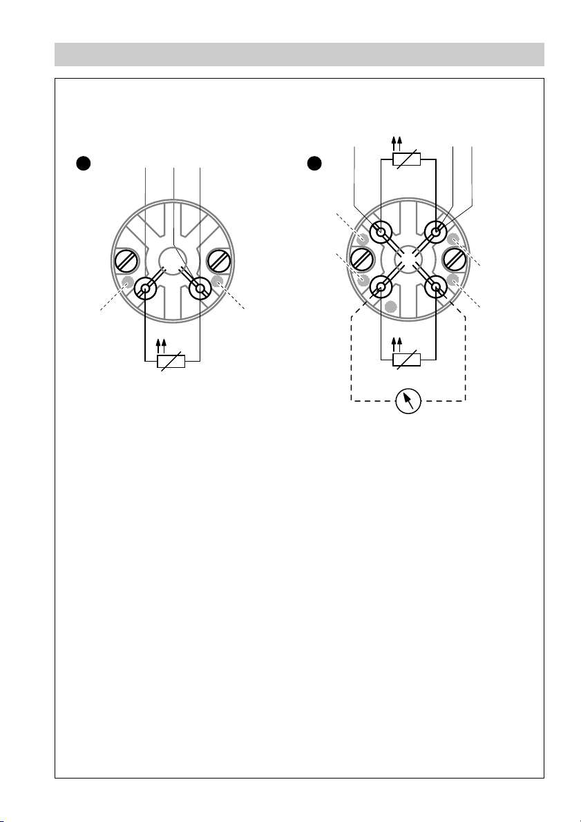
Wiring Diagram
10 12
H I
Red
11
White
ϑ
Fig. 1
10 12
Yellow
Red
Fig. 2
11
ϑ
Black
White
ϑ
3
Page 4
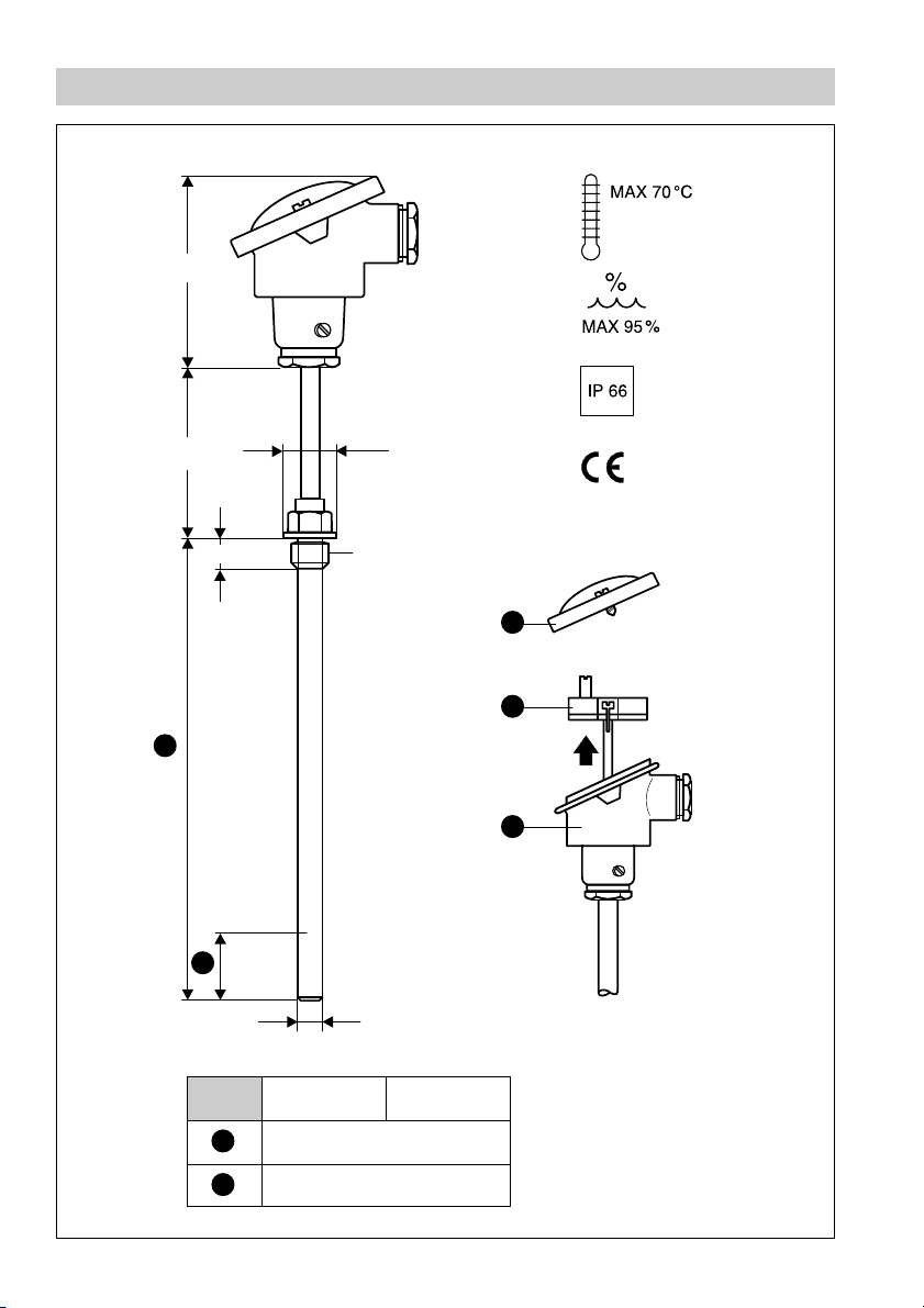
Dimensions
95120
∅ 26
Fig. 3
15
A
D
½" BSP
E
F
G
Fig. 4
∅ 11
TRG 5-53 TRG 5-54
A
D
100, 160, 250, 400
40
4
Page 5
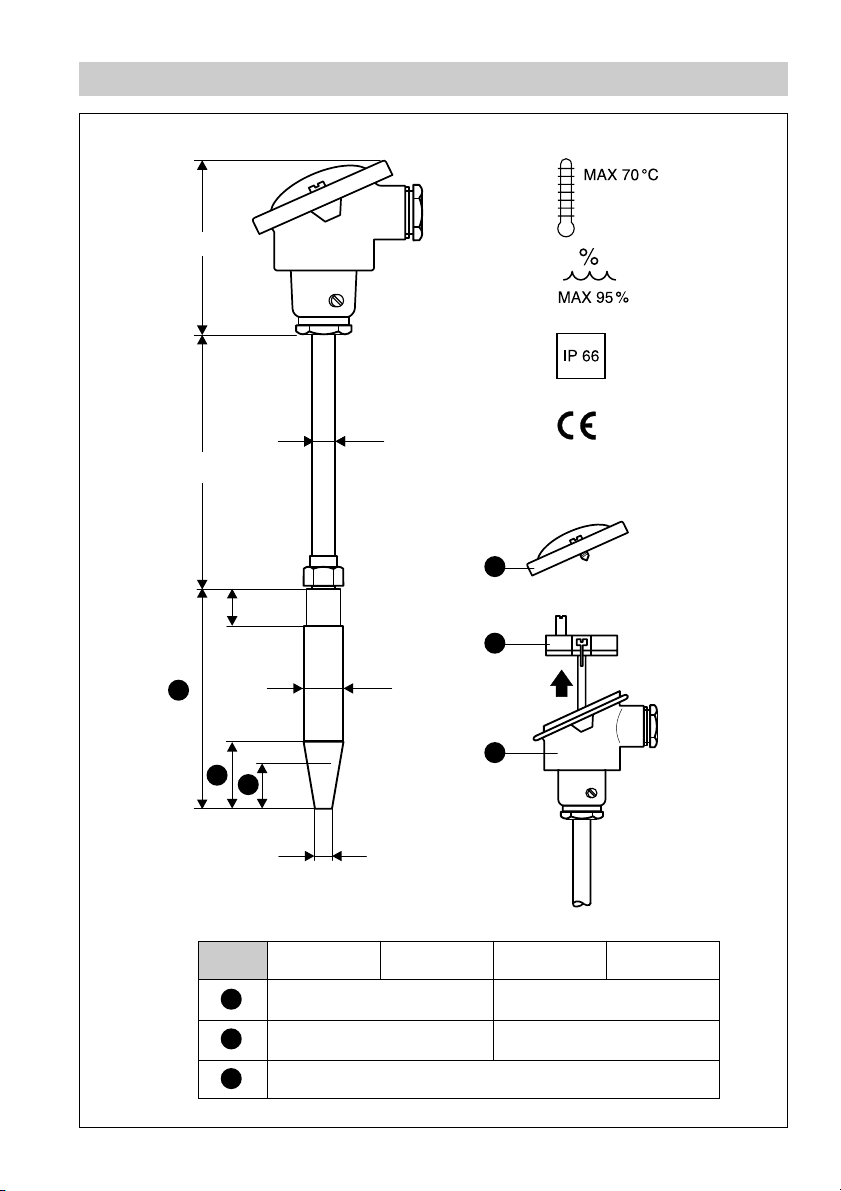
Dimensions
95140
∅ 11
E
25
F
Fig. 4
B
C
D
∅ 18
G
∅ 6
Fig. 5
B
C
D
TRG 5-55
TRG 5-56
115
40
TRG 5-57 TRG 5-58
140
65
30
5
Page 6

Key
A
Protection tube
B
Welding sleeve
C
Tapered part
D
Temperature-sensitive part
E
Cover
F
Temperature sensing element (removable)
G
Body
6
Page 7

Important Notes
Usage for the intended purpose
Use temperature sensors types TRG 5-53, TRG 5-54, TRG 5-55, TRG 5-56,
TRG 5-57 and TRG 5-58 only for measuring temperatures in conjunction with the
associated GESTRA temperature switches.
Safety note
The temperature sensors must only be installed by qualified staff.
Qualified staff are those persons who – through adequate training in electrical
engineering, the use and application of safety equipment in accordance with
regulations concerning electrical safety systems, and first aid & accident
prevention – have achieved a recognised level of competence appropriate
to the installation and commissioning of this device.
Danger
The temperature sensors TRG 5-53 and TRG 5-54 are screwed into
tanks or pipes. When loosening the equipment hot water, steam,
corrosive or poisonous fluids may escape. This presents the danger of
poisoning or severe scalding and acid burns to the whole body.
Installation and maintenance work should only be carried out when the
system is depressurized. Wear protective clothing.
The temperature sensor is hot during operation. This presents the risk
of severe burns to hands and arms.
Installation and maintenance work should only be carried out when the
equipment is cold.
Ratings pursuant to article 9 of the PED1)
Category IV
Description Equipment with safety function
CE marking yes
1
) PED = Pressure Equipment Directive
7
Page 8

Explanatory Notes
Scope of supply
TRG 5-53, TRG 5-54, TRG 5-55, TRG 5-56, TRG 5-57, TRG 5-58
1 Temperature sensor
1 Installation manual
System description
The equipment TRG 5-53, TRG 5-54, TRG 5-55, TRG 5-56, TRG 5-57, TRG 5-58 are
temperature sensors according to DIN 3440.
The temperature sensing element Pt 100 integrated in the protection tube has
temperature-dependent resistance values. The temperature switch TRS 5-6/TRS 5-8
measures the resistance values and raises a temperature alarm correponding to the
adjusted limit.
Application in steam boilers and pressurized hot-water plants acc. to TRD 604 and
other heat-generating units.
Function
The temperature sensors TRG 5-53, TRG 5-54, TRG 5-55, TRG 5-56, TRG 5-57,
TRG 5-58 feature standardized platinum resistance thermometers Pt 100 according
to DIN IEC 751. The temperature sensor in combination with temperature switches
TRS 5-6 or TRS 5-8 are used for temperature monitoring. The power source is
equipped with an adjustable resistor and supplies the resistance thermometer
Pt 100 with a constant current. The desired switch-off temperatures are adjusted with
the aid of the 8 pole code switch on the temperature switch. To ensure a fail-safe
alarm in the event of excessively high temperatures the circuit features relays of the
normally-closed type. In the event of a power failure the temperature switch will raise
an alarm.
Design
TRG 5-53, TRG 5-54:
Temperature sensor with protection tube and ½" screwed terminal box to DIN IEC 751.
The temperature sensing element can be removed.
F
TRG 5-55, TRG 5-56, TRG 5-57, TRG 5-58:
Temperature sensor with protection tube and socket-weld end to DIN IEC 751.
The temperature sensing element can be removed.
F
8
Page 9

Technical Data
Type approval
DIN STW (STB) 98698 S
GL 99251-96 HH
DIN TW 10 6895
EG 01 202931-B-010008
Temperature sensing element
Pt 100 to DIN IEC 751, class B
Service pressure/service temperature
TRG 5-53, TRG 5-54:
nominal length 100/160/250 mm
40 barg (580 psig), 251°C (484 °F)
36 barg (522 psig), 400°C (752 °F)
nominal length 400 mm
18 barg (261 psig), 400°C (752 °F)
TRG 5-55, TRG 5-56, TRG 5-57, TRG 5-58:
160 barg (2321 psig), 345 °C ( 653 °F)
120 barg (1741 psig), 540 °C (1004 °F)
Admissible flow velocity
TRG 5-53, TRG 5-54:
Air 25 m/s
Superheated steam 25 m/s
Water 3 m/s
TRG 5-55, TRG 5-56, TRG 5-57, TRG 5-58:
Air 60 m/s
Superheated steam 60 m/s
Water 5 m/s
Connections
TRG 5-53, TRG 5-54:
Screwed socket ½" BSP
TRG 5-55, TRG 5-56, TRG 5-57, TRG 5-58:
Socket-weld end ∅ 18 mm
Length of protection tube
see “Dimensions”
Materials
TRG 5-53, TRG 5-54:
Protection tube made of S.S.X 6 CrNiMoTi 1712 2 (1.4571)
TRG 5-55, TRG 5-56, TRG 5-57, TRG 5-58:
Protection tube made of forged alloy steel 13 CrMo44 (1.7335)
Weight
TRG 5-53, TRG 5-54:
1.3 kg
TRG 5-55, TRG 5-56, TRG 5-57, TRG 5-58:
0.8 kg
9
Page 10

Installation
TRG 5-53, TRG 5-54
1. Clean sealing surfaces.
2. Put gasket 13 x26 onto the sealing surface (choose the material of the gasket
according to the respective application).
3. Screw in temperature sensor and tighten with spanner when cold (torque 50 Nm).
TRG 5-55, TRG 5-56, TRG-5-57, TRG 5-58
1. Remove socket-weld end from temperature sensor.
2. Clean welding surfaces.
3. Arc-weld trap manually (welding process 111 complying to DIN EN 24063) or use
gas-welding process (welding process 3 complying to DIN EN 24063).
4. After welds have cooled down screw in temperature sensor and tighten with
spanner when cold.
Note
■ To install the temperature sensor in a pipe, weld knee bend to the pipe
such that the measuring tip is immersed in the fluid against the
D
direction of flow. Fig. 8, Fig. 9
■ Make sure that the measuring tip of the installed temperature sensor is
always in contact with the fluid. Fig. 3, Fig. 4
■ The temperature sensors must not be completely insulated. For more
details see examples of installation Fig. 6, Fig. 7
Tools
■ Open-end spanner (A.F. 22 mm or A.F. 27 mm)
■ Torque spanner (A. F. 22 mm or A.F. 27 mm)
K
D
10
Page 11

Wiring
TRG 5-5...
Use four-core cable for wiring:
1. Connect terminal strip acc. to wiring diagram. Fig. 1, Fig. 2
2. You can connect additional equipment to the terminals marked in yellow and black
of the TRG 5-54, TRG 5-56 and TRG 5-58. Fig. 2
Wiring diagram
See wiring diagram on page 3.
Tools
■ Screwdriver for slotted screws, size 2.5, completely insulated to VDE 0680
Commissioning
Measure fluid temperature
Use the following table indicating the resistance of the Pt 100 to ascertain the current
temperature of the fluid.
1. Connect the test wire direct to the terminal box.
2. Measure the resistance with an ohmmeter.
3. Find the corresponding value in the table below, read off the temperature and, if
necessary, determine the exact value by interpolation.
°C 0 102030405060 708090100 Ω/
10
0 100.00 103.90 107.79 111.67 115.54 119.40 123.24 127.07 130.89 134.70 138.50 0.385
100 138.50 142.28 146.06 149.82 153.57 157.32 161.04 164.76 168.47 172.16 175.84 0.373
200 175.84 179.51 183.17 186.82 190.46 194.08 197.70 201.30 204.88 208.46 212.03 0.361
300 212.03 215.58 219.13 222.66 226.18 229.69 233.19 236.67 240.15 243.61 247.06 0.350
400 247.06 250.50 253.93 257.34 260.75 264.14 267.52 270.89 274.25 277.60 280.93 0.338
500 280.93 284.26 287.57 290.87 294.16 297.43 300.70 303.95 307.20 310.43 313.65 0.327
600 313.65 316.86 320.05 323.24 326.41 329.57 332.72 335.86 338.99 342.10 345.21 0.315
700 345.21 348.30 351.38 354.45 357.51 360.55 363.59 366.61 369.62 372.62 375.61 0.304
800 375.61 378.59 381.55 384.50 387.45 390.38 0.295
Basic resistance values according to DIN 43760 for Pt 100
deg
11
Page 12

Operation
Replace temperature sensing element
If necessary the temperature sensing element can be replaced during operation.
F
1. Cut off power supply to temperature sensor.
2. Remove cover . Fig. 4, Fig. 5
E
3. Disconnect wires from terminals.
4. Unscrew the temperature sensing element with a screwdriver.
F
5. Insert new temperature sensing element and fasten with a screwdriver.
6. Connect terminals according to wiring diagram. Fig. 1, Fig. 2
7. Install cover .
E
Annex
Fault finding list
Fault:
Remedy:
Remedy:
If faults occur that are not described here, please contact our subsidiary or agency in
your country.
The temperature switch gives an alarm during normal operation.
Check whether the cable leading to the resistance thermometer is
damaged.
Check the resistance thermometer for correct measuring results
(basic resistance values according to DIN 43760 for Pt 100).
12
Page 13

For your notes
13
Page 14

Annex – continued –
Declaration of conformity
We hereby declare that the equipment TRG 5-53, TRG 5-54, TRG 5-55, TRG 5-56,
TRG 5-57 and TRG 5-58 conform to the following European guidelines:
■
LVD guideline 73/23/eec version 93/68/eec
■
EMC guideline 89/336/eec version 93/68/eec
■
Pressure Equipment Directive (PED) 97/23/EC of 29 May 1997
which are based on the following harmonised standards:
■
LV standard EN 50 178
■
EMC standard EN 50 081-2, EN 50 082-2
■
DIN standard 3440 (relevant for PED)
EC Type Examination (Module B) and Production Quality Assurance (Module D)
according to PED 97/23/eec.
This declaration is no longer valid if modifications are made to the equipment without
consultation with us.
Bremen, 12th June 2001
GESTRA GmbH
Head of the Design Dept.
Uwe Bledschun
Academically qualified engineer
Key
Measuring tip
D
J
Insulating seal
K
Screwed socket
14
Quality Assurance Representative
Lars Bohl
Academically qualified engineer
Page 15

Examples of installation
J J
J
≥ 100
J
Fig. 7
Fig. 6
D
≥ 100
D
Fig. 8
K
K
Fig. 9
15
Page 16

GESTRA Gesellschaften · GESTRA Companies · Sociétés GESTRA · Sociedades Gestra · Società GESTRA
Vertretungen weltweit · Agencies all over the world · Représentations dans le monde entier · Representaciones en todo el mundo · Agenzie in tutto il mondo
Great Britain
Flowserve Flow Control (UK) Ltd.
Burrel Road, Haywards Heath
West Sussex RH 16 1TL
Tel. 00 44 14 44 / 31 44 00
Fax 00 44 14 44 / 31 45 57
E-mail: sales@flowserve.com
España
GESTRA ESPAÑOLA S.A.
Luis Cabrera, 86-88
E-28002 Madrid
Tel. 0034 91 /5152032
Fax 003491/4136747; 5152036
E-mail: gestra@gestra.es
Italia
Flowserve S.p. A.
Flow Control Division
Via Prealpi, 30 – 20032 Cormano (MI)
Tel. 0039 02 /6632 51
Fax 00 39 02 /66 32 55 60
E-mail: infoitaly@flowserve.com
Portugal
Flowserve Portuguesa, Lda.
Av. Dr. Antunes Guimarães, 1159
Porto 4100-082
Tel. 0035122/6198770
Fax 00351 22 /6107575
E-mail: gestra@gestra.pt
®
GESTRA GmbH
P. O. Box 10 54 60, D-28054 Bremen, Münchener Str. 77, D-28215 Bremen
Telephone +49 (0) 421 35 03- 0, Fax +49 (0) 421 35 03 -393
E-Mail gestra.gmbh@flowserve.com, Internet www.gestra.de
A Unit of Flowserve Corporation
810428-02/803c · © 1998 GESTRA GmbH · Bremen · Printed in Germany
16
 Loading...