

Page 1
Automax Valve Automation Systems
Installation, Operation and Maintenance Instructions
Flowserve Corporation 1350 N. Mountain Springs Parkway 1978 Foreman Dr.
Flow Control Division Springville, Utah 84663-3004 Cookeville, TN 38501
www.flowserve.com Phone: 801 489 2233 Phone: 931 432 4021
SNA250 / SNA300
All actuators are factory lubricated for life, but still should be
protected from the elements and stored indoors until ready for
use. The ports of the actuator are plugged as supplied from
the factory. If actuators are stored for a long period of time
prior to installation, the units should be stroked periodically
to prevent the seals from taking a set.
Prior to assembly, check the mounting surfaces, the stem
adaptor and the bracket to assure proper fit. Manually open
and close the valve to insure freeness of operation. Be sure
the valve and Automax actuator rotate in the same direction
and are in the same position (i.e., valve open, actuator open).
Secure the valve with the stem vertical. Bolt the bracket to the
valve and place the stem adaptor on the valve stem. Position
the actuator over the valve and lower to engage the stem
adaptor to the actuator shaft.
Continue to lower until the actuator seats on the bracket
mounting surface. In order to align the bolt holes, it may be
L
L/2
necessary to turn or stroke the actuator a few degrees and/or
adjust the actuators travel stops. Bolt the actuator to the bracket.
After consulting the valve manufacturer’s recommendations,
adjust the travel stop bolts of the actuator for the proper open
or closed valve position. Adjust the Stop Bolt (8) until the
desired travel is obtained and reinstall O-ring (10) and Nut (9).
Pneumatically stroke the actuator several times to ensure
proper operation with no binding of the stem adaptor. If the
actuator is equipped with an UltraSwltch or other accessories,
adjust them at this time.
To prolong actuator life use only clean, dry plant air. Lubricated air is
not required, however it is recommended particularly for high cycle
applications.
CAUTION: Do not use lubricated air with positioners.
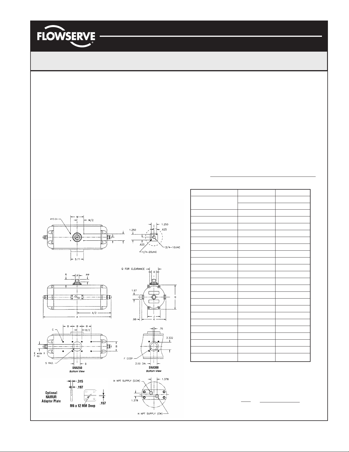
Dimensional Information
MODEL SNA250 SNA300
(DA & SR) 27.32 32.60
A
180° 39.14 44.00
B 4.250 5.000
C 5/8 - 11x.63 5/8 - 11x.86
D 2.87 N/A
E 1.850 N/A
F 1.81 2.50
G 11.02 13.39
H(NPT) 1/2 1/2
J 5.91 6.30
K 11.02 13.39
L 1.181 1.181
M 5.118 5.118
N➁➂ 10 - 24 10 - 24
OØ 2.20 2.44
P 1.969 1.969
PP 0.98 0.98
QØ 3.75 3.75
R 1.65 1.65
S 0.24 N/A
Wts. lbs. (DA) 137 217
Wts. lbs. (SR) 172 288
Volume (IN
Volume (IN
Notes:
➀ Actuators shown in the full clockwise (CW) position as viewed from
the accessory side.
➁ Accessory mounting holes not for gear override or stop block.
Consult factory.
➂ Use studs only to mount. Bolts are not recommended.
④ Air consumption per 90° = V Supply Pressure + 14.7
(Standard cubic feet) 1728 14.7
3
) CW 757 1403
3
) CCW 720 1019
(
)
FCD AXAIM0005-00 (LMR0014-1) (AUTO-5) 03/05 Page 1 of 4
©
2005, Flowserve Corporation, Printed in USA
Page 2
Automax Valve Automation Systems
Installation, Operation and Maintenance Instructions
Flowserve Corporation 1350 N. Mountain Springs Parkway 1978 Foreman Dr.
Flow Control Division Springville, Utah 84663-3004 Cookeville, TN 38501
www.flowserve.com Phone: 801 489 2233 Phone: 931 432 4021
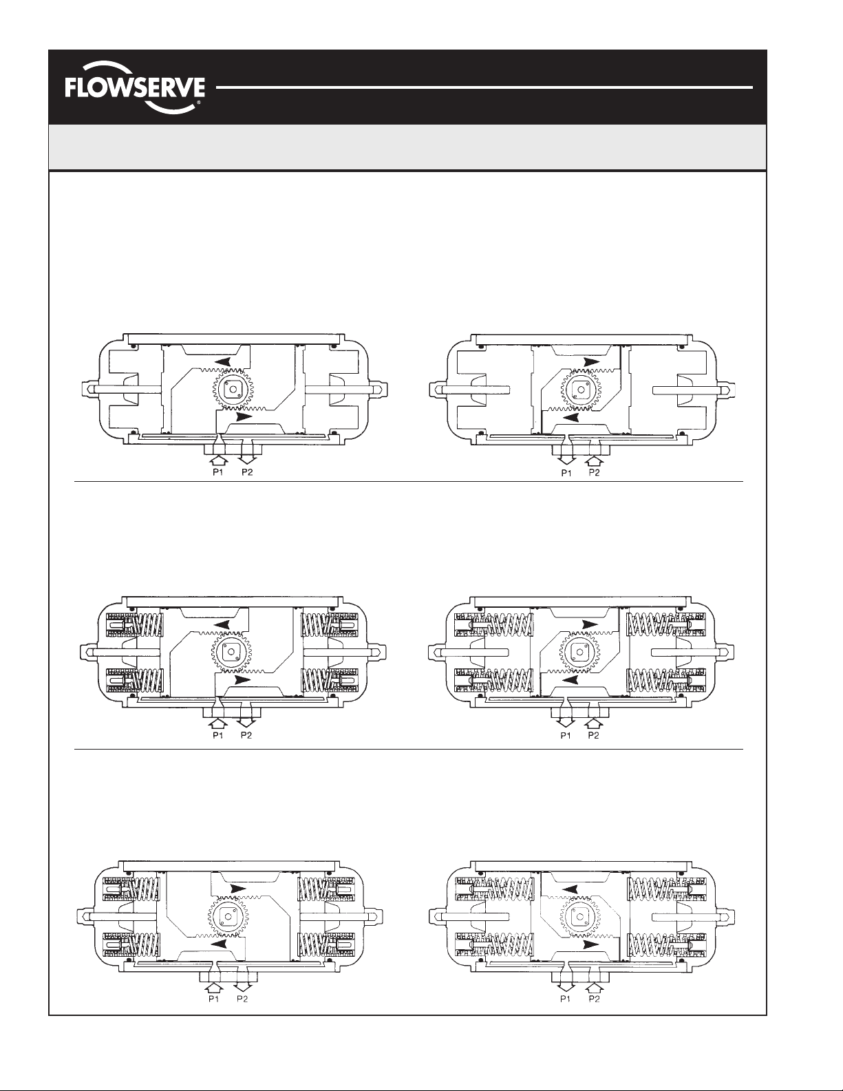
Operation (as viewed from top of actuator)
Double Acting
Applying air pressure to Port 1 drives the pistons Applying air pressure to Port 2 drives the pistons
outward, which turns the pinion counterclockwise as inward, which turns the pinion clockwise as the air
the air volume on the outside of the pistons exhausts volume on the inside of the pistons exhausts through
through Port 2. Port 1.
Spring Return (Fail CW)
Applying air pressure to Port 1 drives the pistons Exhausting the air pressure from Port 1 allows
outward, which compresses the springs and turns stored energy of the springs to drive pistons inward,
the pinion counterclockwise as the air volume on the turning the pinion clockwise. Air volume on outside
outside of the pistons exhausts through Port 2. of pistons vents through Port 2.
Spring Return (Fail CCW)
Applying air pressure to Port 1 drives the pistons Exhausting the air pressure from Port 1 allows stored
outward, which compresses the springs and turns energy of the springs to drive pistons inward, turning
the pinion clockwise as the air volume on the outside the pinion counterclockwise. Air volume on outside of
of the pistons exhausts through Port 2. pistons vents through Port 2.
FCD AXAIM0005-00 (LMR0014-1) (AUTO-5) 03/05 Page 2 of 4
©
2005, Flowserve Corporation, Printed in USA
Page 3

Automax Valve Automation Systems
Installation, Operation and Maintenance Instructions
Flowserve Corporation 1350 N. Mountain Springs Parkway 1978 Foreman Dr.
Flow Control Division Springville, Utah 84663-3004 Cookeville, TN 38501
www.flowserve.com Phone: 801 489 2233 Phone: 931 432 4021
Maintenance Instructions
Disassembly Procedures
1. Disconnect all air and electrical supplies from actuator.
2. Remove all accessories from actuator and dismount
actuator from valve.
3. Remove the 16 Endcap Screws (11, 12). When
removing endcap screws on the supply side, apply low
heat to loosen. Failure to apply heat may result in
broken bolts.
WARNING: Loaded Springs in Endcaps, should be
removed with caution.
4. SR - The Springs (21-24) will push the Endcaps off, releasing the spring load prior to the disengagement of
the Endcap Screws (11, 12). Remove the Endcaps (2)
and Spring Cartridge (21-24).
DA- Remove the Endcaps (2). Step 6 will push the
Endcaps (2) from the Body (1).
5. Rotate Pinion (3) counterclockwise (DA & SR-FCW) or
clockwise (DR & SR-FCCW) to drive the Pistons (16) off
the end of the rack. Pull the Left Piston (16) from the
Body (1).
6. Remove the Right Piston (16) by pushing out through
inside of Body (1).
7. Remove the Pinion Snap Ring (7), and pinion washer
(6).
8. Tap Pinion (3) lightly with plastic mallet to remove.
Reassembly Procedures
1. Inspect all parts for wear and replace any worn parts
as needed. Replace all ‘O’-rings.
2. Clean all components and lightly grease cylinder bore,
pinion and seals per temperature rating notes. See
page 4.
3. Reverse the disassembly procedures to reassemble.
4. The standard Pinion (3) orientation is with the drive
pocket parallel with the Body (1) in the CW position.
5. When fitting the Pistons (16) ensure the teeth engage
the Pinion (3) at the same time by measuring in from
the edge of the Body (1) the same distance from each
end. Note: the orientation of the pistons will determine
the operation of the actuator. Refer to the diagrams
under “Operation” for correct piston position.
6. When assembling a spring return actuator, stand
actuator cylinder vertical when inserting spring
cartridges. If this is not possible, make sure spring
cartridges are fully seated in piston pockets when
installing Endcap.
7. Adjust the Stop Bolt (8) until the desired travel is
obtained and reinstall O-ring (10) and Nut (9).
8. Test the actuator for smooth operation and air leakage
at service pressure before reinstalling.
Changing Number of Springs
Changing Pinion Orientation
1. Disconnect all air and electrical supplies from actuator.
2. Remove all accessories from actuator and dismount
actuator from valve.
3. Remove the Pinion Snap Ring (7) and Pinion Washer
(6).
4. Tap Pinion (3) lightly with plastic mallet to remove.
5. Reverse Steps 3 & 4 with new Pinion (3) orientation.
FCD AXAIM0005-00 (LMR0014-1) (AUTO-5) 03/05 Page 3 of 4
©
2005, Flowserve Corporation, Printed in USA
1. Follow the Disassembly Procedures through step 5.
2. Determine spring combination, consult catalog torque
charts, distributor or factory. Simply add or remove
one or more of the spring cartridges.
3. Reassemble the actuator, paying special note to step 6
in reassembling procedures.
Page 4

Automax Valve Automation Systems
Installation, Operation and Maintenance Instructions
Flowserve Corporation 1350 N. Mountain Springs Parkway 1978 Foreman Dr.
Flow Control Division Springville, Utah 84663-3004 Cookeville, TN 38501
www.flowserve.com Phone: 801 489 2233 Phone: 931 432 4021
Item
No.
1 Body 1 Extruded hard anodized aluminum
2 Endcap 2 Die Cast Aluminum.Electrostatic Poly
3 Pinion 1 Nickel Plated Steel
4 Upper pinion ‘O’-ring ➀ 1 Nitrile rubber
5 Lower pinion ‘O’-ring ➀ 1 Nitrile rubber
6 Pinion washer ➀ 1 Nylon
7 Pinion snap ring ➀ 1 Steel / plated
8 Stop bolt 2 Steel / plated
9 Stop bolt retaining nut 2 Steel / plated
10 Stop bolt ‘O’-ring ➀ 2 Nitrile rubber
11 Endcap screw 8 Stainless steel
12 Endcap screw 8 Stainless steel
13 Piston and Endcap seal ➀ 4 Nitrile rubber
14 Piston guide band 2 PTFE
15 Piston guide 2 PTFE
16 Piston 2 Extruded aluminum
17 Connection base 1 Extruded aluminum, anodized
18 Connection base seal ➀ 2 Nitrile rubber
19 Connection base screw 4 Stainless steel
20 Spring ➁ 12 Steel electrostatic resin coated
21 Spring ➁ 12 Steel electrostatic resin coated
22 Spring Cartridge ➁ 12 Steel / plated
23 Spring Cartridge ➁ 12 Steel / plated
24 Spring Cartridge ➁ 12 Steel / plated
25 NAMUR adaptor plate 1 Aluminum / Anodized
Part Description Qty. Materials
Note:
➀ Parts included in a Seal Kit
➁ See Torque Chart for available combinations
SNA250 / SNA300
Seal Kits
Buna Seal Kit Number NN - (Actuator Model No.) - SK B
Buna Seal Kit Number NN - (Actuator Model No.) - SK V
Seal kit consists of all sealing parts.
Pressure Rating
150 psig maximum
Temperature Ratings
1
Standard
High Temp
Low Temp
Notes:
1
For standard applications, use multi-purpose polymer
fortified grease, such as Dubois Chemicals MPG-2.
2
For low temperature and high temperature applications,
use special formulated grease such as Dow Corning
Nitrile -20° F to +175°F
2
Viton 0°F to +300°F
2
Silicon-based -55°F to +175°F
®
55.
FCD AXAIM0005-00 (LMR0014-1) (AUTO-5) 03/05 Page 4 of 4
©
2005, Flowserve Corporation, Printed in USA
 Loading...