

Page 1
Automax Valve Automation Systems
3-Position Control/Dribble Control
Installation, Operation and Maintenance Instructions
Flowserve Corporation 1350 N. Mountain Springs Parkway 1978 Foreman Dr.
Flow Control Division Springville, Utah 84663-3004 Cookeville, TN 38501
www.flowserve.com Phone: 801 489 2233 Phone: 931 432 4021
SR Limit Switch Method
SuperNova SNA-Series Pneumatic Actuator
All actuators are factory lubricated for life, but still should be
protected from the elements and stored indoors until ready for use.
The ports of the actuator are plugged as supplied from the factory.
If actuators are stored for a long period of time prior to installation,
the units should be stroked periodically to prevent the seals from
taking a set.
Prior to assembly, check the mounting surfaces, the stem adaptor
and the bracket to assure proper fit. Manually open and close the valve
to insure freeness of operation. Be sure the valve and actuator rotate in
the same direction and are in the same position (i.e., valve open,
actuator open). Secure the valve with the stem vertical. Bolt the bracket
to the valve and place the stem adaptor on the valve stem. Position the
actuator over the valve and lower to engage the stem adaptor to the
actuator shaft. Continue to lower until the actuator seats on the bracket
mounting surface. In order to align the bolt holes, it may be necessary
to turn or stroke the actuator a few degrees and/or adjust the actuators
travel stops. Bolt the actuator to the bracket.
After consulting the valve manufacturer's recommendations,
adjust the travel stop bolts of the actuator for the proper open and
closed valve positions. Pneumatically stroke the actuator several times
to assure proper operation with no binding of the stem adaptor. If the
actuator is equipped with an UltraSwitch or other accessories, adjust
them at this time.
To prolong actuator life use only clean, dry plant air. Lubricated
air is not required, however it is recommended particularly for high
cycle applications.
Caution: Do not use lubricated air with positioners.
Actuator Socket Size Socket Size Color Code
SNA050 4mm 3mm White
SNA063 5mm 4mm Light Green
SNA085 6mm 5mm Blue
SNA100 6mm 6mm Red
SNA115 6mm 6mm Yellow
SNA125 8mm 6mm Grey
SNA150 8mm 8mm Dark Green
SNA175 10mm 8mm Purple
SNA200 12mm 8mm Orange
All actuated valves require accurate travel-stop adjustments at both
ends of the stroke to obtain optimum performance and valve seat
life. The accumulation of tolerances in adapting actuators to valves
is such that there must be a range of adjustment for both ends of
the strike to achieve the expected performance.
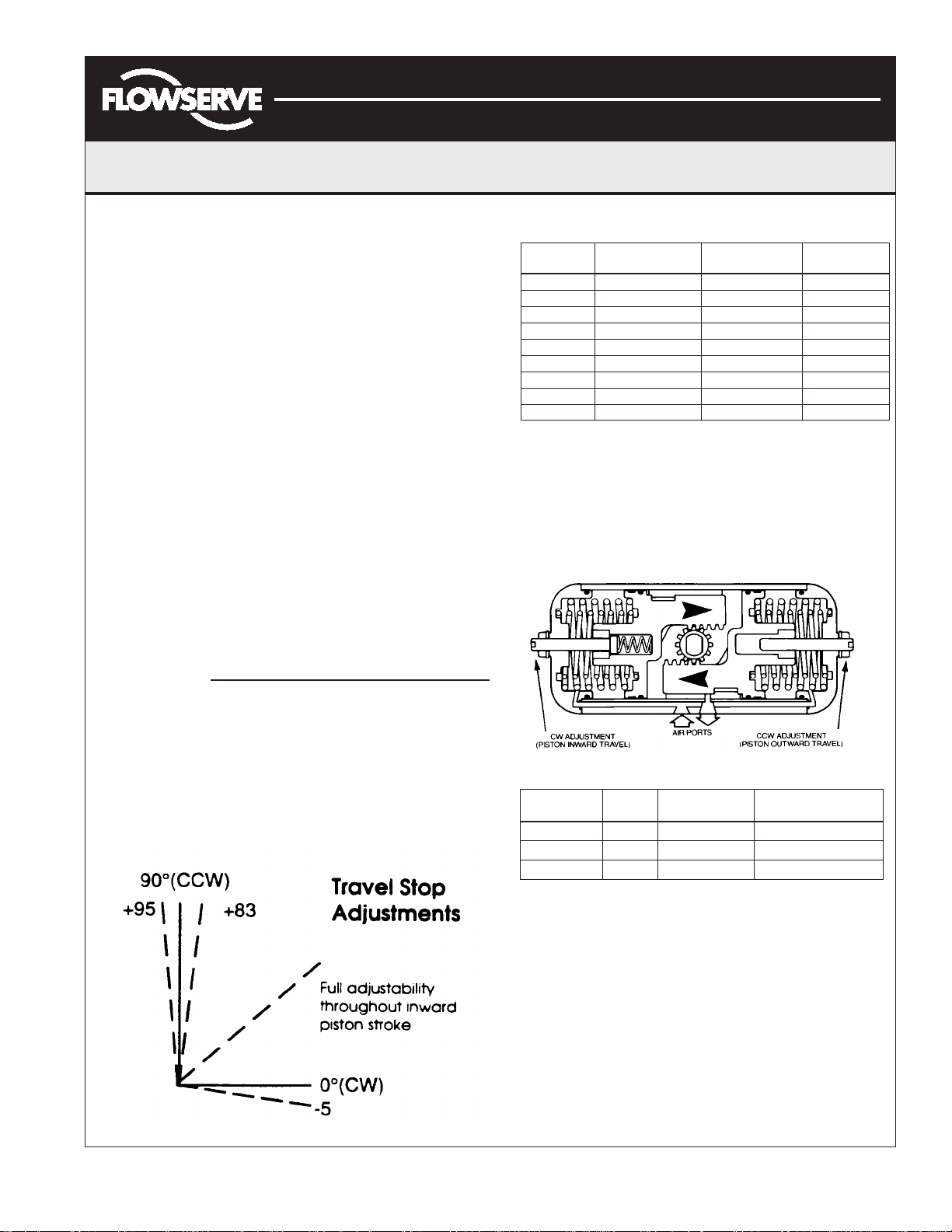
Stop Adjustments and Locations
View the actuator with the Air Ports facing you.
Endcap Screw Adjustment Bolt Spring
Travel Stop Adjustments
Both Directions
The SuperNova actuators have unique travel stop
adjustments in both the clockwise and counterclockwise
directions.
Actuator Fail Clockwise Counterclockwise
Type Position (CW) (CCW)
Double Acting Left End Cap Right End Cap
Spring Return CW Left End Cap Right End Cap
Spring Return* CCW* Right End Cap Left End Cap
*The pistons are rotated 180° for CCW fail position.
Adjustment Bolt Location
Maintenance Instructions
Disassembly Procedures
1. Disconnect all air and electrical supplies from actuator.
2. Remove all accessories from actuator and dismount actuator
from valve.
3. Position actuator with air supply ports facing you. Apply air
pressure to Port 2 to release spring pressure from the Stop
Bolt (9).
4. Remove the Stop Bolt Retaining Nut (14), Washer (15),
and O-ring (16) on the Left Endcap (19) and turn the
Stop Bolt (9) clockwise into the Body (1) until it is flush
with the endcap (19).
FCD AXAIM0004- 01 (AUTO-4) 03/ 11 Page: 1 of 4
© 2011, Flowserve Corporation, Printed in USA
Page 2
Automax Valve Automation Systems
3-Position Control/Dribble Control
Installation, Operation and Maintenance Instructions
Flowserve Corporation 1350 N. Mountain Springs Parkway 1978 Foreman Dr.
Flow Control Division Springville, Utah 84663-3004 Cookeville, TN 38501
www.flowserve.com Phone: 801 489 2233 Phone: 931 432 4021
SR Limit Switch Method
5. Exhaust air from Port 2, the Stop Bolt (9) should now turn
freely. Continue turning Stop Bolt (9) clockwise until it it is
disengaged from the Endcap.
6. Spring Return Actuator:
CAUTION: Follow step 4 to relieve force on inward
travel stop before proceeding.
To remove Spring Return endcap, first completely remove
two diagonal Endcap Screws (21) from one endcap. The two
remaining endcap screws should be removed evenly. As the
screws are removed, the springs will push the endcap out.
Repeat for opposite side. The springs will be totally unloaded
before the screws are completely unthreaded. Remove the
springs (23,24,25).
Double Acting Actuator: Remove the 8 endcap screws (21).
Step (7) will push the endcaps (18,19) from the body (1).
7. Rotate Pinion (3) counterclockwise (DA & SR-FCW) or
clockwise (DR & SR-FCCW) to drive the pistons (2) off the
end of the rack. Pull the left piston (2) from the body (1) by
pulling on the stop bolt (9).
8. Remove the right piston (2) by pushing out through inside of
Body (1).
9. Remove the pinion snap ring (5) and pinion washer (4).
10. Tap pinion (3) lightly with plastic mallet to remove.
Reassembly Procedures
1. Inspect all parts for wear and replace any worn parts as
needed. Replace all O-rings.
2. Clean all components and lightly grease cylinder bore, pinion
and seals per temperature rating notes (page 4).
3. Reverse the disassembly procedures to reassemble.
4. The standard Pinion (3) orientation is with the drive pocket
parallel with the body (1) in the CW position.
5. When fitting the Pistons (2) ensure the teeth engage the
Pinion (3) at the same time by measuring in from the edge of
the body (1) the same distance from each end. Note: The
orientation of the pistons will determine the operation of the
actuator. Refer to the diagrams under Operation for correct
piston position.
6. Test the actuator for smooth operation and air leakage at
service pressure before reinstalling.
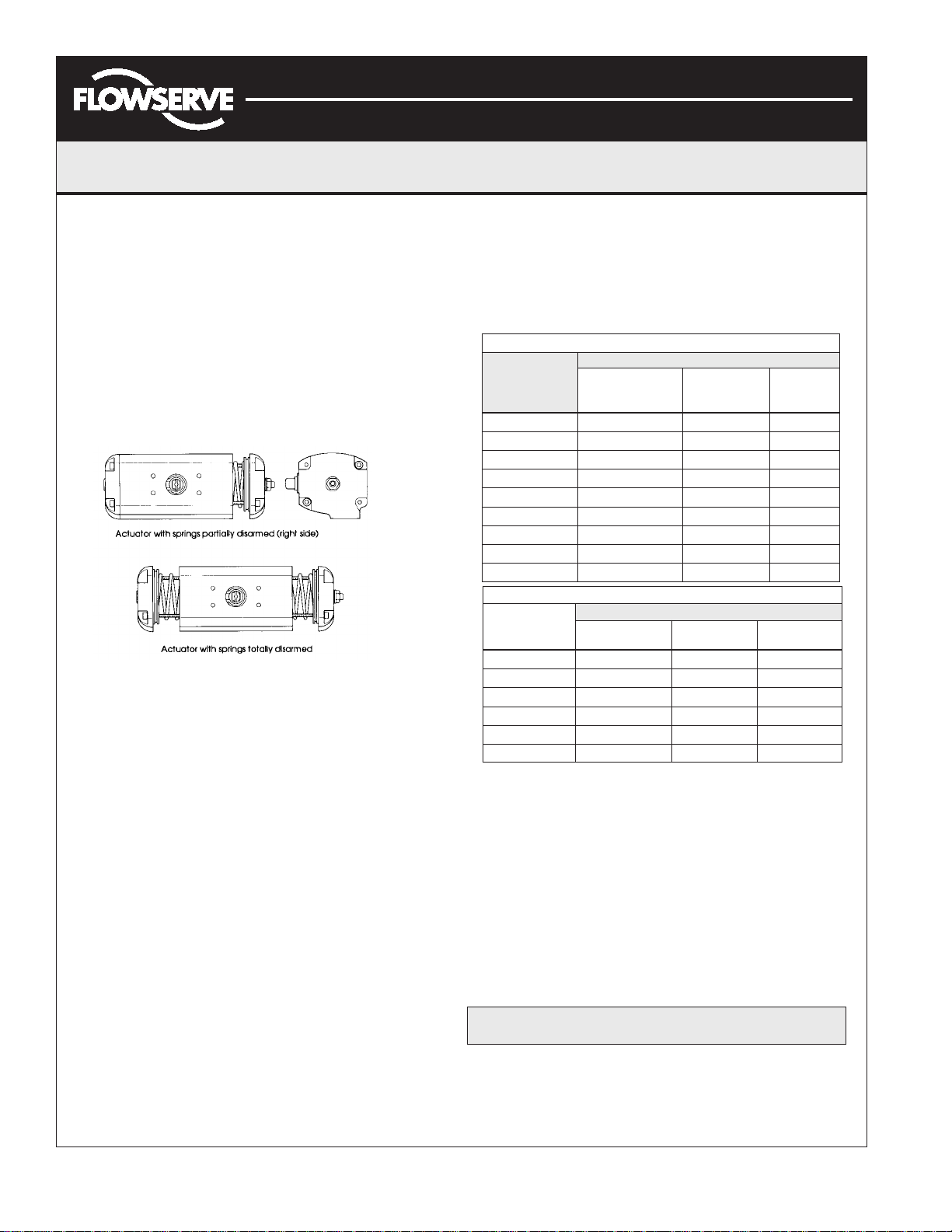
Changing Number of Spring
1. Follow the Disassembly Procedures through step 6.
2. Determine nested spring combination of inner, middle and outer
springs. Consult catalog torque charts, distributor or factory. Insert
appropriate springs into cylinder. Springs must be properly seated
against piston and endcap to assure that springs do not bind.
3. Re-assemble the actuator.
Spring chart SNA063-SNA200
Spring Combination ➀
Spring Group #1 Spring #2 Spring #3 Spring
42
51➂ 1➂
62
71 2
82 2
91➂ 1➂ 2
10 2 2
11 1 2 2
12 2 2 2
Spring chart SNA050 ➁
41➂ 1➂
52
62 1
71 2
82 2
92 2
:
➀ #1 Spring has one color code dot
Note
#2 Spring has two color code dots
#3 Spring has three color code dots
(inner) (middle) (outer)
Spring Combination ➀
#1 Spring #2 Spring #3 Spring
(inner) (low rate outer) (high rate outer)
➁ S50 has maximum of 2 springs
per endcap
➂ Install springs on opposite sides
Changing Pinion Orientation
Note: Steps 4&8 are not required for DA actuator.
1. Disconnect all air and electrical supplies from actuator.
2. Remove all accessories from actuator and dismount actuator
from valve.
3. Position actuator with air supply ports facing you.
4. Follow step 6 under disassembly procedure to unload spring
pressure from right endcap (18) only.
5. Remove the Pinion Snap ring (5) and Pinion Washer (4).
6. Tap Pinion (3) lightly with plastic mallet to remove.
Failure to follow step 4 will result in permanent damage to SR actuator.
7. Reverse steps 5&6 with new pinion (3) orientation.
8. Assembly right endcap (18) in reverse order of disassembly.
Grease endcap screw (21) threads with multipurpose “polymer”
fortified grease, such as Dubois Chemical MPG-2, before
assembly.
Caution:
FCD AXAIM0004- 01 (AUTO-4) 03/ 11 Page: 2 of 4
© 2011, Flowserve Corporation, Printed in USA
Page 3

Automax Valve Automation Systems
3-Position Control/Dribble Control
Installation, Operation and Maintenance Instructions
Flowserve Corporation 1350 N. Mountain Springs Parkway 1978 Foreman Dr.
Flow Control Division Springville, Utah 84663-3004 Cookeville, TN 38501
www.flowserve.com Phone: 801 489 2233 Phone: 931 432 4021
SR Limit Switch Method
Operation (as viewed from top of actuator)
Double Acting
Applying air pressure to Port 2 drives the pistons outward,
which turns the pinion counterclockwise as the air volume on
the outside of the pistons exhausts through Port 1.
Applying air pressure to Port 1 drives the pistons inward,
which turns the pinion clockwise as the air volume on the
inside of the pistons exhausts through Port 2.
Spring Return (Fail CW)
Applying air pressure to Port 2 drives the pistons outward,
which compresses the springs and turns the pinion
counterclockwise as the air volume on the outside of the
pistons exhausts through Port 1.
Spring Return (Fail CCW)
Applying air pressure to Port 2 drives the pistons outward,
which compresses the springs and turns the pinion clockwise
as the air volume on the outside of the pistons exhausts
through Port 1.
Exhausting the air pressure from Port 2 allows stored
energy of the springs to drive pistons inward, turning
the pinion clockwise. Air volume on outside of pistons
vents through Port 1.
Exhausting the air pressure from Port 2 allows stored
energy of the springs to drive pistons inward, turning
the pinion counterclockwise. Air volume on the outside
of pistons vents through Port 1.
FCD AXAIM0004- 01 (AUTO-4) 03/ 11 Page: 3 of 4
© 2011, Flowserve Corporation, Printed in USA
Page 4

Automax Valve Automation Systems
3-Position Control/Dribble Control
Installation, Operation and Maintenance Instructions
Flowserve Corporation 1350 N. Mountain Springs Parkway 1978 Foreman Dr.
Flow Control Division Springville, Utah 84663-3004 Cookeville, TN 38501
www.flowserve.com Phone: 801 489 2233 Phone: 931 432 4021
SR Limit Switch Method
Item
No.
1 Body Hard Anodized Aluminum 1 1
2 Pistons Die Cast Aluminum 2 2
3 Pinion Nickel Plated Steel 1 1
4 Pinion Washer ➀ Nylon 1 1
5 Pinion Snap Ring ➀ Steel/Plated 1 1
6 Upper Pinion O Ring ➀ Nitrile Rubber 1 1
7 Lower Pinion O Ring ➀ Nitrile Rubber 1 1
8 Piston and End Cap O Ring ➀ Nitrile Rubber 4 4
9 Inward Travel Stop Bolt Stainless Steel 1 1
10 Inward Travel Retaining Nut Stainless Steel 1 1
11 Inward Travel Spring Steel/Plated 1 1
12 Piston Guide Nylon and Molybdenum Disulfide 2 2
13 Piston Guide Band Nylon and Molybdenum Disulfide 2 2
14 Stop Bolt Retaining Nut Stainless Steel 2 2
15 Stop Bolt Washer Stainless Steel 2 2
16 Stop Bolt O Ring ➀ Nitrile Rubber 2 2
17 Stop Bolt Stainless Steel 1 1
18 Right End Cap Die Cast Aluminum/Electrostatic Poly 1 1
19 Left End Cap Die Cast Aluminum/Electrostatic Poly 1 1
20 End Cap Supply O Ring Nitrile Rubber 2 2
21 End Cap Screw Stainless Steel 8 8
22 End Cap Screw Washer Stainless Steel 8 8
23 Outer Spring Spring Steel Coated 0 2 max. ➁
24 Middle Spring Spring Steel Coated 0 2 max. ➁
25 Inner Spring Spring Steel Coated 0 2 max. ➁
Part Description
Materials
Quantity
DA SR
Note: ➀ Parts included in Seal Kit.
➁ See spring chart for required spring combination.
Seal Kits
Buna Seal Kit Number
Viton Seal Kit Number
Low Temperature
Seal
Kit Number
SN kits consist of all sealing parts, snap ring and washers.
SN (Actuator Model No.) SKB
SN (Actuator Model No.) SKV
S (Actuator Model No.) SKF
Pressure Rating
150 psig maximum
Temperature Ratings
Standard ● Nitrile -20°F to +175°F
High Temp ▲ Viton 0°F to +300°F
Low Temp ▲ Silicon-based -55°F to +175°F
Notes:
● For standard applications use multi-purpose
polymer fortified grease, such as Dubois
Chemicals MPG-2.
▲ For low temperature and high temperature
applications, use special formulated grease
such as Dow Corning® 55.
FCD AXAIM0004- 01 (AUTO-4) 03/ 11 Page: 4 of 4
© 2011, Flowserve Corporation, Printed in USA
 Loading...