

Page 1
USER INSTRUCTIONS
Limitorque
FCD LMENIM1401-04-AQ – 1/15
®
SMB Series/SB Series
Installation
Operation
Maintenance
Experience In Motion
Page 2

SMB Series/SB Series Installation and Maintenance FCD LMENIM1401-04-AQ – 01/15
Contents
1 Introduction 6
2 Product Capabilities and Features 7
3 Actuator Weights 10
4 Installation Instructions 11
4.1 Safety Precautions 11
4.2 Safety Practices 12
4.3 Actuator Preparation 12
4.3.1 Mounting Base 13
4.3.2 Stem Acceptance 13
4.3.3 Terminal Connections 14
4.4 Setting The Limit Switch 14
4.4.1 Two-Train Geared Limit Switch 15
4.4.2 Four-Train Geared Limit Switch 18
4.5 Setting Torque Switch 20
4.5.1 SMB-000 “Cam Style” Double Torque Switch 20
4.5.2 SMB-000 and SMB-00 “C Style” Double Torque Switch 23
4.5.3 SMB-0 through SMB-5 Double Torque Switch 25
4.6 Position Indication 27
4.6.1 Local Position Indicator 27
4.6.2 Remote Position Indicator (50 ohm or 1000 ohm Potentiometer) 27
4.6.3 Remote Position Indicator (Resistance-to-Current Signal Converter) 28
4.7 Additional Electrical Components 30
4.7.1 Reversing Starter 30
4.7.2 Overload Relays 30
4.7.3 Control Station 31
5 Operation 32
5.1 Motor Operation 32
5.2 Manual Operation 33
5.2.1 SMB-000 and SMB-00 33
5.2.2 SMB-0 through SMB-4 34
5.2.3 SMB-5 through SMB-5T 34
6 Maintenance 35
6.1 Routine Maintenance 35
6.2 Major Maintenance 36
6.3 Lubrication 36
6.3.1 Lubrication Inspection 36
6.3.2 Standard Lubricant 37
6.3.3 Minimum Lubricant Qualities Required 38
7 SMB Disassembly and Reassembly 39
7.1 SMB-000 39
2
7.1.1 To Replace the Stem Nut Only 39
Page 3

SMB Series/SB Series Installation and Maintenance FCD LMENIM1401-04-AQ – 01/15
7.1.2 SMB-000 Disassembly 40
7.1.3 SMB-000 Reassembly 41
7.1.4 Gasket Instructions 41
7.2 SMB-00 46
7.2.1 To Replace the Stem Nut Only 46
7.2.2 SMB-00 Disassembly 47
7.2.3 SMB-00 Reassembly 48
7.2.4 Gasket Instructions 49
7.3 SMB-0, 1, 2, 3 and 4 57
7.3.1 To Replace the Stem Nut Only 57
7.3.2 SMB-0, 1, 2, 3 and 4 Disassembly 58
7.3.3 Worm and Torque Spring Disassembly 59
7.3.4 SMB-0, 1, 2, 3 and 4 Reassembly 60
7.3.5 Gasket Instructions 60
7.4 SMB-5 (Thrust and Torque) and SMB-5T (Torque Only) 67
7.4.1 SMB-5 and SMB-5T Disassembly 67
7.4.2 SMB-5 and SMB-5T Reassembly 70
8 SB Disassembly and Reassembly 80
8.1 SB-00 80
8.1.1 SB-00 Disassembly/Stem Nut Removal 80
8.1.2 SB-00 Reassembly/Stem Nut Installation 81
8.2 SB-0 84
8.2.1 SB-0 Disassembly/Stem Nut Removal 84
8.2.2 SB-0 Reassembly/Stem Nut Installation 85
8.3 SB-1 88
8.3.1 SB-1 Disassembly/Stem Nut Removal 88
8.3.2 SB-1 Reassembly/Stem Nut Installation 88
8.4 SB-2 91
8.4.1 SB-2 Disassembly/Stem Nut Removal 91
8.4.2 SB-2 Reassembly/Stem Nut Installation 92
8.5 SB-3 95
8.5.1 SB-3 Disassembly/Stem Nut Removal 95
8.5.2 SB-3 Reassembly/Stem Nut Installation 96
8.6 SB-4 99
8.6.1 SB-4 Disassembly/Stem Nut Removal 99
8.6.2 SB-4 Reassembly/Stem Nut Installation 99
9 Troubleshooting 103
10 How to Order Parts 104
11 EC Declaration of Conformity 105
flowserve.com
3
Page 4

SMB Series/SB Series Installation and Maintenance FCD LMENIM1401-04-AQ – 01/15
Figures
Figure 2.1 – Typical SMB (0 through 4) 8
Figure 4.1 – Wiring Connections 14
Figure 4.2 – Two-Train Geared Limit Switch – Rotor-Type 16
Figure 4.3 – Four-Train Geared Limit Switch – Rotor Type 18
Figure 4.4 – SMB-000 “Cam Style” Double Torque Switch 21
Figure 4.5 – SMB-000 and SMB-00 “C Style” Double Torque Switch 23
Figure 4.6 – SMB-0 through SMB-5 Double Torque Switch 25
Figure 4.7 – Typical Connection for a 50-ohm Potentiometer 29
Figure 4.8 – Typical Connection for a 1000-ohm Potentiometer 29
Figure 4.9 – Typical Connection for R/I Signal Converter (Older Version) 29
Figure 4.10 – Typical Connection for PT20SD R/I Converter 30
Figure 4.11 – Typical Wiring Diagram – Built-in Reversing Starter and Control Station for a
Three-Phase Power Supply 31
Figure 7.1 – SMB-000 Parts Diagram – Side View 42
Figure 7.2 – SMB-000 Parts Diagram – Top View 43
Figure 7.3 – SMB-000 Exploded View 44
Figure 7.4 – SMB-00 Parts Diagram – Motor End View 50
Figure 7.5 – SMB-00 Parts Diagram – Top View 51
Figure 7.6 – SMB-00 Parts Diagram – Side View 52
Figure 7.7 – SMB-00 Parts Diagram – Side Mounted Handwheel Detail 53
Figure 7.8 – SMB-00 Exploded View 54
Figure 7.9 – SMB-0 through SMB-4 Parts Diagram – Top View 61
Figure 7.10 – SMB-0 through SMB-4 Parts Diagram – Worm Shaft Side View 62
Figure 7.11 – SMB-0 through SMB-4 Parts Diagram – Drive Sleeve Side View 63
Figure 7.12 – SMB-0 through SMB-4 Exploded View 64
Figure 7.13 – SMB-5 and 5T Parts Diagram 73
Figure 7.14 – SMB-5 and 5T Parts Diagram– Top View 74
Figure 7.15 – SMB-5 and 5T Parts Diagram – Declutch Housing Detail 75
Figure 7.16 – SMB-5 and 5T Exploded View 76
Figure 8.1 – SB-00 Parts Diagram 82
Figure 8.2 – SB-0 Parts Diagram 86
Figure 8.3 – SB-1 Parts Diagram 89
Figure 8.4 – SB-2 Parts Diagram 93
Figure 8.5 – SB-3 Parts Diagram 97
Figure 8.6 – SB-4 Parts Diagram 101
4
Page 5

Tables
SMB Series/SB Series Installation and Maintenance FCD LMENIM1401-04-AQ – 01/15
Table 3.1 – Actuator Weights
Table 4.1 – Mounting Base Dimensions 13
Table 4.2 – Maximum Stem Acceptance 13
Table 4.3– Terminal Connections 14
Table 4.4 – Two-Train Geared Limit Switch Parts List 17
Table 4.5 – Four-Train Geared Limit Switch Parts List 19
Table 4.6 – SMB-000 “Cam Style” Double Torque Switch Parts List 22
Table 4.7 – SMB-000 and SMB-00 “C Style” Torque Switch Parts list 24
Table 4.8 – SMB-0 through SMB-5 Double Torque Switch Parts List 26
Table 6.1 – Approximate Volume and Weights of Lubricants 37
Table 7.1 – SMB-000 Parts List 45-46
Table 7.2 – SMB-00 Parts List 55-57
Table 7.3 – SMB-0 through SMB-4 Parts List 65-67
Table 7.4 – SMB-5 and 5T Parts List 77-79
Table 8.1 – SB-00 Parts List 83-84
Table 8.2 – SB-0 Parts List 87
Table 8.3 – SB-1 Parts List 90
Table 8.4 – SB-2 Parts List 94
Table 8.5 – SB-3 Parts List 98
Table 8.6 – SB-4 Parts List 102
Table 10.1 – Space Heater Size per Voltage Rating 104
10
flowserve.com
5
Page 6

1
SMB Series/SB Series Installation and Maintenance FCD LMENIM1401-04-AQ – 01/15
Introduction
1.1 Purpose
This Installation and Maintenance Manual explains how to install and maintain SMB and SB actuators. Information on installation, operation, disassembly, lubrication, and spare parts is provided.
1.2 User Safety
Safety notices in this manual detail precautions the user must take to reduce the risk of personal
injury and damage to the equipment. The user must read and be familiar with these instructions
before attempting installation, operation, or maintenance. Failure to observe these precautions could
result in serious bodily injury, damage to the equipment, void of the warranty, or operational difficulty.
Safety notices are presented in this manual in three forms:
c WARNING: Refers to personal safety. Alerts the user to potential danger. Failure to follow warning
notices could result in personal injury or death.
a CAUTION: Directs the user’s attention to general precautions that, if not followed, could result in
personal injury and/or equipment damage.
NOTE: Highlights information critical to the user’s understanding of actuator installation and
operation.
6
Page 7

2
SMB Series/SB Series Installation and Maintenance FCD LMENIM1401-04-AQ – 01/15
Product Capabilities and Features
SMB and SB Series actuators easily operate all types of valves: gate, globe, plug, ball, and butterfly
valves, and specialized valves and mechanisms.
The actuators meet rigid safety requirements. The housing is durable cast-iron or ductile iron,
acceptable for use in the nuclear power industry as well as other industries.
The actuators are available with optional integral controls and other features.
The actuators have a removable stem nut that allows transferring of the actuator from one valve to
another without major disassembly.
2.1 Initial Inspection and Storage Instructions
c WARNING: Read this Installation and Maintenance Manual carefully and completely before
attempting to install, operate, disassemble, or troubleshoot the actuator. Be aware of the electrical
hazards.
2.2 Product Identification
The actuator unit nameplate is located on the back of the unit opposite the limit switch compartment. The nameplate contains the following information:
• Point of Manufacture
• Unit Size
• Order Number
• Serial Number
• Customer Tagging
• CE Stamp
7
flowserve.com
Page 8
SMB Series/SB Series Installation and Maintenance FCD LMENIM1401-04-AQ – 01/15
The motor nameplate is located on the motor. The nameplate contains the following information:
• ID Number
• Run Torque
• RPM
• Full Load Amps
• Insulation Class
• Horsepower
• Service Factor
• Hertz
• Ambient Temperature
• Start Torque
• Enclosure Type
• Volts
• Locked Rotor Amps
• Duty
• Phase
• Motor Code
• Connection Diagram
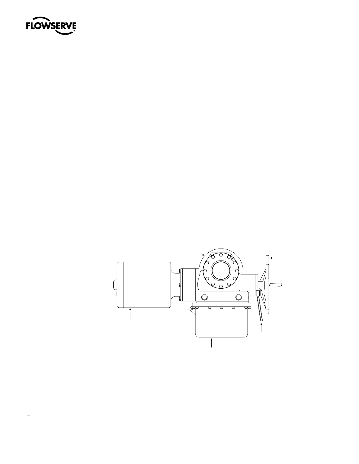
Figure 2.1 – Typical SMB (0 through 4)
Housing
Motor
Handwheel
Declutch lever
Switch compartment
8
Page 9

SMB Series/SB Series Installation and Maintenance FCD LMENIM1401-04-AQ – 01/15
2.3 Inspection and Recording
Upon receipt of the actuator:
1. Carefully remove the actuator from the shipping carton or skid. Thoroughly examine the equipment for any physical damage that may have occurred during shipment. If damaged, immediately
report the damage to the transport company.
2. A nameplate is attached to each actuator. Record this information for future reference, i.e.
ordering parts or obtaining further information.
2.4 Storage Procedure
NOTE: The following is our recommended storage procedure to retain maximum product integrity
during storage. Failure to comply with recommended procedures will void the warranty. For longerterm storage, contact Limitorque for procedures and recommendations.
Storage (less than 1 year)
Actuators are not weatherproof until properly installed on the valve or prepared for storage.
Store actuators in a clean, dry, protected warehouse, away from excessive vibration and rapid
temperature changes. If the actuators must be stored outside, they must be stored off the ground,
high enough to prevent them from being immersed in water or buried by snow.
1. Position the actuator in storage with motor and switch compartment horizontal.
2. Connect the internal heaters (if supplied) or place desiccant in the switch compartment.
3. Replace all plastic caps or plugs with metal pipe plugs and ensure that all cover bolts are tight.
4. If the actuator is mounted on a valve and the stem protrudes from the actuator, a suitable stem
cover must be provided.
flowserve.com
9
Page 10

SMB Series/SB Series Installation and Maintenance FCD LMENIM1401-04-AQ – 01/15
3
Actuator Weights
The approximate weights of the SMB actuators and SB and SBD options are provided below:
Table 3.1 – Actuator Weights
Actuator
SMB-000 135 62 N/A N/A N/A N/A
SMB-00 200 90 65 30 100 46
SMB-0 350 159 180 83 210 97
SMB-1 460 209 200 92 325 150
SMB-2 580 263 220 101 345 159
SMB-3 1200 553 500 230 825 380
SMB-4 2020 916 795 366 1285 591
SMB-5&5T 3375 1531 N/A N/A N/A N/A
SMB-5XT 5875 2665 N/A N/A N/A N/A
Note 1: With the largest motor, no integral controls, and standard compartment cover.
1
1
Weight
lb. kg lb. kg lb. kg
Adder for SB Adder for SBD
10
Page 11

4
SMB Series/SB Series Installation and Maintenance FCD LMENIM1401-04-AQ – 01/15
Installation Instructions
4.1 Safety Precautions
c WARNING: Read this Installation and Maintenance Manual carefully and completely before
attempting to install, operate, or troubleshoot the Limitorque actuator.
c WARNING: Be aware of electrical hazards. Turn off incoming power before working on the
actuator and before opening the switch compartment.
c WARNING: Potential HIGH PRESSURE vessel — be aware of high-pressure hazards associated
with the attached valve or other actuated device when installing or performing maintenance on
the actuator. Do not remove the actuator mounting bolts from the valve or actuated device unless
the valve or device stem is secured or there is no pressure in the line.
c WARNING: For maintenance and/or disassembly of the actuator while installed on the valve,
ensure that the actuator is not under thrust or torque load. If the valve must be left in service, the
valve stem must be locked in such a way as to prevent any movement of the valve stem.
c WARNING: Do not attempt to remove the spring cartridge cap, housing cover, or stem nut
locknut from the actuator while the valve or actuated device is under load.
c WARNING: Do not manually operate the actuator with devices other than the installed handwheel
and declutch lever. Using force beyond the ratings of the actuator and/or using additive force
devices such as cheater bars, wheel wrenches, pipe wrenches, or other devices on the actuator
handwheel or declutch lever may cause serious personal injury and/or damage to the actuator
and valve.
c WARNING: Do not exceed any design limitations or make modifications to this equipment
without first consulting Limitorque.
c WARNING: Actuators equipped with electrical devices (motors, controls) requiring field wiring
must be wired and checked for proper operation by a qualified tradesman.
c WARNING: Use of the product must be suspended any time it fails to operate properly.
flowserve.com
11
Page 12

SMB Series/SB Series Installation and Maintenance FCD LMENIM1401-04-AQ – 01/15
a CAUTION: Do not use oversized motor overload heaters. Instead, look for the cause of the
overload.
a CAUTION: Do not operate the valve under motor operation without first setting or checking the
limit switch setting and motor direction.
a CAUTION: Do not force the declutch lever into the motor operation position. The lever returns to
this position automatically when the motor is energized.
a CAUTION: Do not depress the declutch lever during motor operation to stop valve travel.
a CAUTION: Do not use replacement parts that are not genuine Flowserve Limitorque parts, as
serious personal injury and/or damage to the actuator and valve may result.
a CAUTION: Do not lift actuator/gearbox or actuator/valve combinations with only the eye bolts in
the SMB actuator. These eye bolts are designed for lifting the SMB actuator only.
a CAUTION: Do not lift the actuator by the handwheel
4.2 Safety Practices
The following check points should be performed to maintain safe operation of the SMB or SB
actuator:
• Eye bolts in SMB and SB actuators are designed for lifting only the actuator and not associated
gearboxes or valves.
• Mount the actuator with the motor in a horizontal plane, if possible.
• Keep the switch compartment clean and dry.
• Keep the valve stem clean and lubricated.
• Set up a periodic operating schedule for infrequently used valves.
• Verify all actuator wiring is in accordance with the applicable wiring diagram.
• Carefully check for correct motor rotation direction. If the valve closes when open button is
pushed, the motor leads may have to be reversed.
• Verify the stem nut is secured tightly by the locknut and that the top thread of the locknut is
crimped or staked in two places.
• Use a protective stem cover. Check valve stem travel and clearance before mounting covers on
rising stem valves.
4.3 Actuator Preparation
Replace all molded plastic conduit and top protectors (installed for shipping purposes only) with
metal pipe plugs when installation wiring is complete.
12
Page 13

SMB Series/SB Series Installation and Maintenance FCD LMENIM1401-04-AQ – 01/15
4.3.1 Mounting Base
Table 4.1 – Mounting Base Dimensions
Mounting Holes Tap Dimensions
Actuator Quantity Standard Optional
SMB-000 4
SMB-00 4
SMB-0 4 ¾-10 UNC x 1.00" deep M20-2.5 x 26 mm deep
SMB-1 8
SMB-2 8 ¾-10 UNC x 1.13" deep M20-2.5 x 29 mm deep
SMB-3 8
SMB-4 8 1¼-7 UNC x 2.00" deep M36-4 x 64 mm deep
SMB-5 12 1½-6 UNC x 3.00" deep N/A
SMB-5T 16 1-8 UNC x 2.00" deep N/A
SMB-5XT 16 Consult Factory N/A
5
⁄16-18 UNC x .63" deep N/A
5
⁄8-11 UNC x 1.13" deep M16-2 x 29 mm deep
5
⁄8-11 UNC x 1.00" deep M16-2 x 26 mm deep
7
⁄8-9 UNC x 1.75" deep M30-3.5 x 45 mm deep
4.3.2 Stem Acceptance
Table 4.2 – Maximum Stem Acceptance
Two-piece nut design (drive sleeve & stem nut) Max threaded Max bore & keyway
Actuator inch mm inch mm
3
SMB-000 1.375 35 1.125 w/ ¼ x
SMB-00 1.75 44 1.500 w/
SMB-0 2.375 60 1.875 w/ ½ x
SMB-1 2.875 73 2.438 w/
SMB-2 3.5 89 2.875 w/ ¾ x ¼ 73.0 w/ 20x6
SMB-3 5 127 4.250 w/ 1.0 x
SMB-4 5 127 4.500 w/ 1.0 x ½ 114.0 w/ 32x9
SMB-5 6.25 159 5.250 w/ 1¼ x
SMB-5T N/A N/A 6.000 w/1 ½ x ½ 152.0 w/ 40x11
SMB-5XT N/A N/A 10.000 w/ 1¼ x
SB-00 1.25 32
SB-0 2.375 60
SB-1 2.625 66
SB-2 3.50 89
SB-3 4.00 102
SB-4 5.00 127
⁄32 26.0 w/ 8x3.5
3
⁄8 x 1⁄8 37.0 w/ 10x4
3
⁄16 48.0 w/ 14x4.5
5
⁄8 x 7⁄32 62.0 w/ 18x5.5
3
⁄8 108.0 w/ 28x8
7
⁄16 133.0 w/ 36x10
5
/8 N/A
flowserve.com
13
Page 14

SMB Series/SB Series Installation and Maintenance FCD LMENIM1401-04-AQ – 01/15
4.3.3 Terminal Connections
Wiring connections to the SMB geared limit switch, torque switch, and Marathon terminal strips are
to be made using ring-tongue terminals* as shown below:
Figure 4.1 – Wiring Connections
A
C
B
Table 4.3– Terminal Connections
AWG Screw Hole Insulation
22-16 #10 Vinyl 18RA-10 .97 .31 .27
18-14 #10 Vinyl 14RB-10 .97 .31 .27
12-10 #10 Vinyl 14RC-10 1.06 .31 .27
Note: Limit switch and torque switch contacts are rated 300 volts per NEMA ICS-2
Thomas &
Betts P/N
A B C
14
Terminals are to be crimped using Thomas & Betts crimping tool WT112M or ERG4001.
Manufacturer: *Thomas and Betts or equal
4.4 Setting The Limit Switch
c WARNING: Disconnect all incoming power before opening or replacing the limit switch compart-
ment cover.
a CAUTION: When wiring control circuits, distinguish between “normally open” and “normally
closed” terminals on the geared limit switch.
a CAUTION: Do NOT attempt to repair the limit switch gear box. Replace entire limit switch gear
box.
a CAUTION: Do NOT use abrasive cloth to clean the silver contacts on the limit switch. Contacts
should be burnished using appropriate burnishing tool.
a CAUTION: Before motor operation, reset the geared limit switch if the actuator has been
dismantled or removed from the valve.
NOTE: Clean the limit switch cover thoroughly and apply a thin coat of grease on machined flange
surfaces before mounting on an explosion proof actuator.
Page 15

SMB Series/SB Series Installation and Maintenance FCD LMENIM1401-04-AQ – 01/15
4.4.1 Two-Train Geared Limit Switch
The rotor-type, two-train geared limit switch employs two rotors. Each rotors contains four contacts.
When the rotor is properly set to trip at the desired position, two of these contacts open electric
circuits and two of the contacts close electric circuits. One rotor is normally set to trip at the full open
position of the valve, and the other rotor is normally set to trip at the full close position of the valve.
Each rotor may be adjusted independently of the other:
• First rotor—one circuit is used to open the “open” holding coil circuit of the motor controller, one
circuit is used to control the “open” indicating light.
• Second rotor—one circuit is used to open the “close” holding coil circuit of the motor controller,
one circuit is used to control the “closed” indicating light.
For the geared limit switches to trip at any desired position, follow the setting procedure below.
Piece numbers refer to Figure 4.2 and Table 4.4.
1. Verify all power is OFF.
2. Using the handwheel, manually open the valve to the full open position. See Section 5.2 Manual
Operation. Note the direction of rotation of the Intermittent Gear Shaft (piece #42), located over
the Rotor (piece #49) to be set.
3. Using a screwdriver, turn the Set Rod (piece #48) clockwise until it reaches a stop position.
4. If the Rotor (piece #49) you are setting has not turned 90° to open the contacts that should trip
open at this position, insert screwdriver on the Intermittent Gear Shaft (piece #42). Turn in the
direction noted in Step No. 4 until the Rotor (piece #49) turns and opens the contacts to be set.
5. If the Rotor (piece #49) has turned so that the contacts are already open, turn the Intermittent
Gear Shaft (piece #42) in the opposite direction as previously noted in Step No. 4 until the
contacts close. Turn the Intermittent Gear Shaft (piece #42) slightly in the direction noted in Step
No. 4 until the contacts open. The Rotor (piece #49) is set at the correct position for contact
opening.
Note: In the contact “Close” position, ensure a gap exists between the contact finger and the
L-bracket as seen in figure 4.2
6. Back off the Set Rod (piece #48) until it stops. Place the screwdriver on the Intermittent Gear
Shaft (piece #42) to ensure that the shaft is tight and will not rotate. Do not force.
7. Close the valve completely. Repeat Step No. 1 through 6 to set the tripping position for the other
Rotor (piece #49).
flowserve.com
15
Page 16
SMB Series/SB Series Installation and Maintenance FCD LMENIM1401-04-AQ – 01/15
64 66 67
65
63
62
56
63
42 49
50 41 51 47 43 46 44 52 1
2
Figure 4.2 – Two-Train Geared Limit Switch – Rotor-Type
63
Contact Finger
62
42
56
GAP
GAP
65
64
5 10 3
67
66
L-Bracket
68
69
71
54
9
16
11 6 8 7 55 4 58 45 48 53
61
Page 17

SMB Series/SB Series Installation and Maintenance FCD LMENIM1401-04-AQ – 01/15
Table 4.4 – Two-Train Geared Limit Switch Parts List
Piece Description
1 Cartridge
2 Drive Sleeve and Shaft
3 Drive Pinion
4 Drive Pinion (Secondary)
5 Declutch Spring
6 Bushing
7 O-Ring
8 Pin
9 Groove Pin
10 Washer
11 Oil Seal
41 Gear Frame
42 Intermittent Gear Shaft
43 Intermittent Pinion Shaft
44 Geared Limit Frame Cover
45 Intermittent Gear
46 Intermittent Pinion
47 Stem Spur Pinion
48 Set Rod
49 Rotor
50 Groove Pin
51 Cover Gasket
52 Long Fillet Head Machine Screw
53 O-Ring
54 Setting Rod Bushing
55 Gear Frame Gasket
56 Insert (Rotor)
57 O-Ring (For Intermittent Gear Shaft piece #42) (Not shown)
58 Groove Pin
61 Finger Base
62 Right Hand Finger Assembly
63 Left Hand Finger Assembly
64 Long Hex Head Machine Screw
65 Lockwasher
66 Hex Nut
67 Washer
68 Long Fillet Head Cap Screw
69 Internal Tooth Lockwasher
71 Flat Washer
flowserve.com
17
Page 18
SMB Series/SB Series Installation and Maintenance FCD LMENIM1401-04-AQ – 01/15
25
46
43
53 41
54
48
61
4.4.2 Four-Train Geared Limit Switch
The rotor-type, four-train geared limit switch employs four rotary drum switches. Each rotary drum
switch contains four contacts. When the rotor is properly set to trip at the desired position, two of
these contacts open electric circuits and two of the contacts close electric circuits. One rotor is set
to trip at the full open position of the valve, and one rotor is set to trip at the full close position of the
valve. The other two rotors are set at some intermediate position depending on the application.
For the geared limit switches to trip at any desired position, follow the steps in Section 4.4.1,
Two-Train Geared Limit Switch, with the exception that the piece numbers refer to Figure 4.3 and
Table 4.5.
NOTE: The upper Set Rod (piece #48) allows adjustment of the two adjacent upper rotors, and the
lower Set Rod (piece #48) allows adjustment of the two adjacent lower rotors.
Figure 4.3 – Four-Train Geared Limit Switch – Rotor Type
18
26
21
35
22 23
34
26
24
28
27
30
31
32
29
5552445845
42
57 47 50 49
68
69
71
01-472-0007-3
01-472-0007-3
Page 19

SMB Series/SB Series Installation and Maintenance FCD LMENIM1401-04-AQ – 01/15
Table 4.5 – Four-Train Geared Limit Switch Parts List
Piece Description
21 Cartridge
22 Oilite Bushing
23 Drive Shaft
24 Drive Pinion (Internal)
25 Helical Pinion
26 Groove Pin
27 Drive Sleeve and Gear
28 Declutch Spring
29 Drive Pinion Spur
30 Pin
31 Cartridge Gasket
32 Cartridge Mounting Plate
33 Long Socket Head Cap Screw and Lockwasher
34 O-Ring
35 O-Ring
36 Fillet Head Cap Screw and Lockwasher
41 Gear Frame
42 Intermittent Gear Shaft
43 Intermittent Pinion Shaft
44 Geared Limit Frame Cover
45 Intermittent Gear
46 Intermittent Pinion
47 Stem Spur Pinion
48 Set Rod
49 Rotor
50 Groove Pin
51 Cover Gasket
52 Long Fillet Head Machine Screw
53 O-Ring
54 Setting Rod Bushing
55 Gear Frame Gasket
56 Insert (Rotor)
57 O-Ring
58 Groove Pin
61 Finger Base
62 Right Hand Finger Assembly
63 Left Hand Finger Assembly
64 Long Hex Head Cap Screw
65 Lockwasher
66 Hex Nut
67 Washer
68 Long Fillet Head Cap Screw
69 Internal Tooth Lockwasher
71 Flat Washer
19
flowserve.com
Page 20

SMB Series/SB Series Installation and Maintenance FCD LMENIM1401-04-AQ – 01/15
4.5 Setting Torque Switch
The torque switch is designed to protect the actuator in open and close directions.
c WARNING: Disconnect all incoming power before working on the torque switch.
c WARNING: Do not attempt to remove either the spring cartridge cap or the housing cover from
the actuator while the valve is torque-seated.
a CAUTION: Do not use abrasive cloth to clean the contacts on the torque switch.
a CAUTION: A maximum stop setting plate is furnished on all actuators. Do not exceed this
maximum setting without consulting Limitorque.
NOTE: See Section 4.3.3 for wiring connection requirements.
4.5.1 SMB-000 “Cam Style” Double Torque Switch
NOTE: Torque settings must be made with the switch mounted in the actuator.
Piece numbers correspond to Figure 4.4 and Table 4.6.
To set the torque switch:
1. Verify all electric power is OFF.
2. Loosen Pan Head Screws (piece #30).
3. For open or close operation, set Striker (piece #25) to the required torque setting. Match the edge
of the Striker with the desired number. The higher the number, the higher the torque output of the
actuator.
4. Tighten Pan Head Screws (piece #30).
5. For torque seated valves, operate the valve electrically to seat the valve. Ensure tight shut-off by
tripping the torque switch contacts.
20
Page 21

SMB Series/SB Series Installation and Maintenance FCD LMENIM1401-04-AQ – 01/15
28
91211105 6481437
Figure 4.4 – SMB-000 “Cam Style” Double Torque Switch
5
4
3
2
1
1
5
2
4
3
7
38
39
25
27
23 21 321937 36
A
A
30 32 312522
20
27 24 25 26 25 23 22
44
17 11618333435
21 43 20
2
45
13
15
SECTION A-A
B
42
42
VIEW B-B
B
29
01-474-0056-4
01-474-0056-4
21
flowserve.com
Page 22

22
SMB Series/SB Series Installation and Maintenance FCD LMENIM1401-04-AQ – 01/15
Table 4.6 – SMB-000 “Cam Style” Double Torque Switch Parts List
Piece Description
1 Terminal Block
2 Contact Block
3 Contact Screw
4 Finger Holder
5 Finger
6 Shunt
7 Shunt Washer
8 Rivet
9 Finger Spring Stud
10 Compression Spring
11 Spring Cup Washer
12 Cotter Pin
13 Hex Head Machine Screw
14 Ring Tongue Connector
15 Shakeproof Lockwasher, Internal Teeth
16 Torque Switch Mounting Bracket
17 O-Ring
18 O-Ring
19 Socket Head Cap Screw
20 Cam
21 Torsion Spring
22 Spring Mandrel
23 Dial
24 Shaft
25 Striker
26 Torque Limiting Plate
27 Striker Hub
28 Roll Pin
29 Swage Nut
30 Pan Head Screw
31 Shakeproof Lockwasher, External Teeth
32 Flatwasher
33 Arm
34 Roller
35 Roller Pin
36 Groove Pin
37 Arc Barrier
38 Pan Head Screw
39 Lockwasher, External Tooth
42 Spring Pin
43 Cam Insert
44 Bushing (For piece #16)
45 Washer
Page 23

SMB Series/SB Series Installation and Maintenance FCD LMENIM1401-04-AQ – 01/15
43
4.5.2 SMB-000 and SMB-00 “C Style” Double Torque Switch
NOTE: Torque settings must be made with the switch mounted in the actuator.
NOTE: See Section 4.3.3 for wiring connection requirements.
Piece numbers correspond to Figure 4.5 and Table 4.7.
To set the torque switch:
1. Verify all electric power is OFF.
2. For the open or close direction torque switch, loosen Machine Screw (piece #35) and set Pointer
(piece #7) at the desired torque setting. The higher the number, the higher the torque output of
the actuator.
3. Tighten Machine Screw (piece #35).
4. For torque seated valves, operate the valve electrically to seat the valve. Ensure tight shut-off by
tripping the torque switch contacts.
Figure 4.5 – SMB-000 and SMB-00 “C Style” Double Torque Switch
23
8
14
1
44
13
17
33
2
25
46
11
5
30
34
25
31
39
27
27
29 16
42
47
4
3
45
27
36
5
4
3
2
1
3
2
1
48
6
51
37
20
25
12
9
35
39/52
7
41
27/50
18
01-473-0056-3
01-473-0056-3
2122101528
23
flowserve.com
Page 24

24
SMB Series/SB Series Installation and Maintenance FCD LMENIM1401-04-AQ – 01/15
Table 4.7 – SMB-000 and SMB-00 “C Style” Double Torque Switch Parts List
Piece Description
1 Terminal Block
2 Contact Block
3 Hex Nut - Remove and discard
4 Contact Arm
5 Dial
6 Actuating Link
7 Pointer
8 Tripper Arm
9 Shaft
10 Contact Support
11 Torque Limiter Plate
12 Bushing (SMB-00 only)
13 Roller
14 Roller Pin
15 Contact Finger
16 Terminal Stud
17 Compression Spring
18 Torsion Spring
20 Bearing
21 O-Ring
22 O-Ring
23 Groove Pin
25 Thrust Washer
27 Lockwasher
28 Groove Pin
29 Hex Nut
30 Hex Nut
31 Cotter Pin
33 Pan Head Machine Screw
34 Hex Socket Set Screw
35 Round Head Machine Screw
36 Round Head Machine Screw
37 Insulating Material
39 Flatwasher
41 Round Head Machine Screw
42 Lockwasher, Internal Teeth
43 Socket Head Cap Screw
44 Lockwasher
45 Mounting Bracket
46 Dial Plate (SMB-00 only)
47 Socket Head Cap Screw
48 Lockwasher (SMB-000 only)
49 Insulator (SMB-000 only) - Not Shown
50 Lockwasher (SMB-000 only)
51 Lockwasher (SMB-000 only)
52 Lockwasher (SMB-000 only)
Page 25

SMB Series/SB Series Installation and Maintenance FCD LMENIM1401-04-AQ – 01/15
01-473-0057-3
4.5.3 SMB-0 through SMB-5 Double Torque Switch
NOTE: Torque settings must be made with the switch mounted in the actuator.
NOTE: See Section 4.3.3 for wiring connection requirements.
Piece numbers correspond to Figure 4.6 and Table 4.8.
To set the torque switch:
1. Verify all electric power is OFF.
2. For the open or close direction torque switch, loosen Machine Screw (piece #35) and set Pointer
(piece #7) at the desired torque setting. The higher the number, the higher the torque output of
the actuator.
3. Tighten Machine Screw (piece #35).
4. For torque seated valves, operate the valve electrically to seat the valve. Ensure tight shut-off by
tripping the torque switch contacts.
Figure 4.6 – SMB-0 through SMB-5 Double Torque Switch
8
23
12
5
4
3
3
2
1
3
2
1
13
25
1
2
43
44
17
33
25
37
30
34
25
4
45
35
39
5
7
11
31
42
47
3
20
27
39
27
29 16
36
6
41
27
18
9
01-473-0057-3
2122101528
25
flowserve.com
Page 26

SMB Series/SB Series Installation and Maintenance FCD LMENIM1401-04-AQ – 01/15
Table 4.8 – SMB-0 through SMB-5 Double Torque Switch Parts List
Piece Description
1 Terminal Block
2 Contact Block
3 Hex Nut - Remove and Discard
4 Contact Arm
5 Dial
6 Actuating Link
7 Pointer
8 Pinion
9 Shaft
10 Contact Support
11 Torque Limiter Plate
12 Bushing
13 Spacer
15 Contact Finger
16 Terminal Stud
17 Compression Spring
18 Torsion Spring
20 Bearing
21 O-Ring
22 O-Ring
23 Pin
25 Thrust Washer
27 Lockwasher
28 Pin
29 Hex Nut
30 Hex Nut
31 Cotter Pin
33 Pan Head Self-Tapping Screw
34 Hex Socket Set Screw
35 Round Head Machine Screw
36 Round Head Machine Screw
37 Insulating Material
39 Flatwasher
41 Round Head Machine Screw
42 Lockwasher, Internal Teeth
43 Socket Head Cap Screw
44 Lockwasher
45 Mounting Bracket
47 Socket Head Cap Screw
26
Page 27

SMB Series/SB Series Installation and Maintenance FCD LMENIM1401-04-AQ – 01/15
4.6 Position Indication
4.6.1 Local Position Indicator
NOTE: The local dial position indicator displays valve position. The position indicator can only be
adjusted when the actuator is mounted on the valve. See Figures 7.1-7.3 (SMB-000), 7.4-7.8 (SMB-
00), 7.9-7.12 (SMB-0 through 4), 7.13-7.16 (SMB-5).
To set the position indicator:
1. Disconnect all incoming power and open or remove the Limit Switch Compartment Cover.
2. Place the valve in the fully “close” position.
3. Loosen the round head machine screw that holds the pointer in place, move the pointer to the
“C” position, and retighten the screw.
The indicator is now set.
4.6.2 Remote Position Indicator
(50 ohm or 1000 ohm Potentiometer)
The SMB or SB actuator with a potentiometer installed, transmits a 0-10 VDC output signal to a
remote position indicator (meter). The potentiometer is powered by 120 VAC.
To set the potentiometer:
NOTE: The pinion has been disengaged to prevent damaging the potentiometer prior to setting the
valve.
1. Set the potentiometer by turning the pinion until the desired reading is obtained.
2. Loosen the hex nut on the back of the potentiometer and slide the potentiometer in the direction
of the idler pinion until the pinions are engaged.
3. Do not force the engagement of the pinions.
4. Retighten the hex nut on the back of the potentiometer.
5. Do not engage the pinion until the actuator and valve positions have been set.
To calibrate the potentiometer:
1. Position the valve at 50% of full travel.
2. Read the resistance from the wiper to either end of the potentiometer.
3. To set the potentiometer to the proper value, loosen the set screw on the potentiometer shaft
pinion and rotate the potentiometer shaft to a reading of ~500 ohms for the 1000-ohm potentiometer, or ~25 ohms for the 50-ohm potentiometer.
4. Tighten the set screw.
5. Run the actuator to the fully CLOSED position.
6. Adjust the CLOSED position setting to a value at or above 0 ohms.
7. Run the actuator to the fully OPEN position.
27
flowserve.com
Page 28

SMB Series/SB Series Installation and Maintenance FCD LMENIM1401-04-AQ – 01/15
8. Adjust the OPEN position setting to a value at or below 1000 ohms for the 1000-ohm potentiometer; at or below 50 ohms for the 50-ohm potentiometer.
9. Repeat steps 5 through 8 and fine-tune as necessary.
4.6.3 Remote Position Indicator
(Resistance-to-Current Signal Converter)
The SMB or SB actuator with a signal converter installed transmits a 4-20 mA output signal to a
remote position indicator (meter). The signal converter responds to the input of a 1000-ohm
potentiometer and can be powered by 24 VDC or 120 VAC for the older version R/I converter; or
18 VDC, 24 VDC, or 120 VDC for the PT20SD style R/I converter.
To set the R/I signal converter:
NOTE: The pinion has been disengaged to prevent damaging the potentiometer prior to setting the
valve.
1. Set the potentiometer by turning the pinion until the desired reading is obtained.
2. Loosen the hex nut on the back of the potentiometer and slide the potentiometer in the direction
of the idler pinion until the pinions are engaged.
3. Do not force the engagement of the pinions.
4. Retighten the hex nut on the back of the potentiometer.
5. Do not engage the pinion until the actuator and valve positions have been set.
To calibrate the R/I signal converter:
1. Position the valve at 50% of full travel.
2. Read the ohms from the wiper to either end of the potentiometer.
3. To set the potentiometer to the proper value, loosen the set screw on the potentiometer shaft
pinion and rotate the potentiometer shaft to a reading of 500 ohms.
4. Tighten the set screw.
5. Run the actuator to the fully CLOSED position.
6. Adjust the ZERO control to an output of 4 mA.
7. Run the actuator to the fully OPEN position.
8. Adjust the SPAN control to an output of 20 mA.
9. Repeat steps 5 through 8 to fine-tune as necessary.
28
Page 29
SMB Series/SB Series Installation and Maintenance FCD LMENIM1401-04-AQ – 01/15
Remote position indicator
0-10 volts full scale deflection
Control voltage range
110 volts to 480 volts
Potentiometer 1000 ohm 2 Watt
customer’s equipment
terminal as valve opens
Figure 4.7 – Typical Connection for a 50-ohm Potentiometer
25 Watt, 50 OHM Potentiometer type
variable resistor mounted in SMB/SB housing
Voltmeter
type
P3P2P1
RES
175 Watt, 2500 ohm Adjustable resistor
to be located adjacent to remote position indicator
Figure 4.8 – Typical Connection for a 1000-ohm Potentiometer
for voltage adjustment
in limit switch housing
(CCW)
P1
Potentiometer slider rotates
toward counter clockwise (CCW)
Figure 4.9 – Typical Connection for R/I Signal Converter (Older Version)
4-20 mA
Output Signal
P2
P3
(CW)
To
91
(–)90(+)CL2CL1
1000 ohm
P1
POT
P2
P3
91 90 CL2 CL1 P1 P2 P3
(–) (+)
R to I
Signal Converter
PC Board
Connection
29
flowserve.com
Page 30

SMB Series/SB Series Installation and Maintenance FCD LMENIM1401-04-AQ – 01/15
POT
24 VDC or
18 VAC
See comments
under Section
4.6.3,
Figure 4.10 – Typical Connection for PT20SD R/I Converter
1000 ohm
(S)
4-20 mA
Output
Signal
(+)
(–)
(+)
(–)
BLU
BLU
18V
115V
Black
Brown
Orange
Green
1
2
3
4
5
6
(CCW)
(+)m A
(–)m A
+V
COM
Signal Converter
1 BLK
3 RED
2 BRN
CCW SC W
1
2
3
LK2
1
AC
2
DC
3
LK3
(CW )
4.7 Additional Electrical Components
4.7.1 Reversing Starter
The reversing starter electrically changes the operation of the electric motor from one direction
of rotation to the other. The starter consists of two contactors mounted on a common base and
mechanically interlocked.
Each contactor consists of the following:
• three normally open power contacts
• one normally open circuit holding contact
• one normally closed interlock
• one magnetic holding coil.
30
The starter can be provided two ways:
• Mounted within the actuator limit switch compartment
• Supplied in a separate enclosure
4.7.2 Overload Relays
Overload relays de-energize the holding coils of the reversing starter, which open the power contacts
to de-energize the electric motor. The relays function at a predetermined current value and can reset
either automatically or manually as follows:
• Reset automatically if mounted as detailed in Figure 4.11.
• Reset manually if the reversing starter is furnished separately.
The relays are sized in accordance with full load (running) motor current.
Page 31

SMB Series/SB Series Installation and Maintenance FCD LMENIM1401-04-AQ – 01/15
L1
M1
o
4.7.3 Control Station
The control station consists of
• a five-position Local-Stop-Off-Stop-Remote selector switch, padlockable in each position
• a spring return Open-Close selector switch
• green and red LED lights for position indication.
Typical wiring of the control station in conjunction with the motor control circuit is shown below in
Figure 4.11.
Figure 4.11 – Typical Wiring Diagram – Built-in Reversing Starter and Control Station for a
Three-Phase Power Supply
T1
L2
L3
o
o
C
M2
M3
OL
OL
OL
T2
Motor
T3
CL1
CL1
CL1
CL1
CL1
PB2
STOP
Black
LOCAL
Red
Green
4
8
53
C
C
18
43
17
To customer’s
equipment
45
5
55
1
Remote
indication
if required
HTR1
HTR2
C
o
White
47
57
CL2
CL2
CL2
2
OL
CL2
(H1)(H3) (H2)(H4)
CPT
(X1) (X2)
FUSE
SS
OFF
REMOTE
3
11
3
30
7
5
5
Purple
9
31
Gray
7
3
OPEN
5
5
Brown
Orange
Pink
70
60
PB1
41
Yellow
PB3
CLOSE
51
o
C
CLOSE (51)
COMMON (11)
STOP (9)
REMOTE (31)
REMOTE (30)
Blue
OPEN (41)
NOTE: Current design. Earlier control wiring varies slightly.
31
flowserve.com
Page 32

5
SMB Series/SB Series Installation and Maintenance FCD LMENIM1401-04-AQ – 01/15
Operation
c WARNING: See Section 4.1 and 4.2 on Safety Precautions and Safety Practices prior to
operation.
5.1 Motor Operation
Actuator motors are high-starting torque, totally enclosed motors. The motors are furnished in
weatherproof, explosionproof, or submersible enclosures. The motors are furnished with ball bearings and provided with grease seals. All three-phase AC motors are squirrel-cage design and all DC
motors are compound wound.
Piece numbers refer to Figure 7.9 through 7.11. However, this description is applicable to all models.
The piece numbers will differ for each model.
The electric motor has a Motor Pinion (piece #40) mounted on its shaft extension. This pinion drives
the Worm Shaft Clutch Gear (piece #41), which is engaged with the Worm Shaft Clutch (piece #50).
The Worm Shaft Clutch is splined to the Worm Shaft (piece #43). The Worm (piece #53) is splined to
the Worm Shaft (piece #43), and when it is rotated, it turns the Worm Gear (piece #16).
The Worm Gear has two lugs cast onto the top portion that engage the two lugs on the Drive Sleeve
(piece #11). These lugs are spaced so that when the Worm Gear begins to turn during motor operation there is a certain amount of lost motion before the lugs engage, causing the hammer blow effect
within the actuator.
32
As soon as the Worm Gear Lugs engage, the Drive Sleeve, splined internally with the Stem Nut (piece
#20), causes the stem nut to rotate and open or close the valve. The Stem Nut is threaded to fit the
thread of any rising stem valve. In the case of non-rising stem valves, the electric actuator may be
mounted in tandem with an additional gear drive, and the Stem Nut (piece #20) is bored and keyed to
fit the shaft.
Page 33

SMB Series/SB Series Installation and Maintenance FCD LMENIM1401-04-AQ – 01/15
The thrust developed by the actuator is absorbed by the heavy-duty Bearings (piece #75, 76, 77,
78) on the top and bottom of the main Drive Sleeve. As the actuator develops greater torque, when
seating the valve, the Worm (piece #53) slides axially along the splines of the Worm Shaft (piece #43)
and compresses the Belleville Springs (piece #56) in the torque spring pack.
The Belleville Springs are calibrated springs. For every increment of compression from a given size
unit, a certain pre-determined amount of torque is developed. The Worm mechanically actuates
the Torque Switch. When the Worm moves back a preset distance and develops the torque output
required, the Torque Switch opens and a pair of electrical contacts that are wired into the motor
control circuit interrupt the circuit and stop the motor.
The Geared Limit Switch (piece #105) is directly geared to the Worm Shaft and is in step at all times
with the movement of the actuator. The switch cannot slip because no belts or other friction devices
are used in its operation. Once the Geared Limit Switch (piece #105) is set to trip at its proper position of valve travel, it will trip at the same point every time.
The Torque Switch (piece #104) is wired into the motor control circuit to stop the actuator in the full
closed position for any rising stem operation. The Geared Limit Switch (piece #105) is wired into
the motor control circuit to stop the operator at the full open position. For most 90° turn valves and
sluice gates, the Geared Limit Switch is wired into the motor control circuit to stop the actuator at
both the full open and full close position of the valve or gate. The Torque Switch is wired in series
with the Geared Limit Switch in both directions so that in the event of a mechanical overload, the
Torque Switch will open and cause the motor to stop.
Check the applicable wiring diagram to determine the correct wiring connections made for the torque
switch and geared limit switch.
5.2 Manual Operation
In the event of a power failure, the actuator can be operated by hand using the handwheel. The
actuator has an automatic handwheel declutching arrangement. For manual operation, the declutch
lever is pulled downward. This mechanically disconnects the electric motor from the handwheel
through the clutch assembly.
5.2.1 SMB-000 and SMB-00
The operation of the SMB-000 and SMB-00 are functionally the same. Due to a difference in piece
numbers between these actuators, the following description refers to the SMB-000 (Figures 7.1 to
7.3).
For the SMB-000 and the SMB-00, the Clutch Ring (piece #33) and the Clutch Keys (piece #23) are
moved upward until the Clutch Keys engage with the lugs on the bottom of the Handwheel (piece #5).
For the side-mounted Handwheel on the SMB-00, the Clutch Keys engage the lugs on the bottom of
the Bevel Gear (piece #100).
Trippers (piece #28, 29) hold the Clutch Keys in this position. The actuator will remain in hand operation indefinitely until the electric motor is energized and the Tripper Cams (piece #27) mounted on the
flowserve.com
33
Page 34

SMB Series/SB Series Installation and Maintenance FCD LMENIM1401-04-AQ – 01/15
Worm Shaft (piece #21) cause the trippers to release the Clutch Ring (piece #33) and the Clutch Keys
(piece #23) from their hand position. This is an automatic feature of the actuator.
5.2.2 SMB-0 through SMB-4
Piece numbers refer to Figures 7.9 to 7.11.
The declutching action is similar to that of the smaller SMB actuators. When the Declutch Lever
(piece #10) is depressed, the Declutch Shaft (piece #24) causes the Declutch Fork (piece #12) to
push the Worm Shaft Clutch (piece #50) out of engagement with the worm shaft clutch gear (piece
#41) and into engagement with the Handwheel Clutch Pinion (piece #42). The Clutch Trippers
(piece #32) lock the worm shaft clutch in this position. When the Handwheel (piece #5) is rotated,
the Handwheel Gear (piece #7) turns the Handwheel Clutch Pinion (piece #42) and the Worm Shaft
(piece #43), placing the actuator into manual operation.
When the electric motor is energized, the Tripper Pins (piece #51), which are part of the Worm Shaft
Clutch Gear (piece #41), cause the Trippers to be released, allowing the Worm Shaft Clutch (piece
#50) to be released from hand operation and engage in motor operation.
For all actuator sizes, when the handwheel is turned, the motor does not rotate; and when the motor
is in operation, the handwheel does not rotate in manual operation.
5.2.3 SMB-5 through SMB-5T
Piece numbers refer to Figures 7.13 to 7.16.
The declutching action is similar to that of the smaller SMB-0 through 4 actuators. When the
Declutch Lever (piece #9) is depressed, the rotation of the Declutch Shaft (piece #30) causes the
Declutch Fork (piece #14) to push the Sliding Gear Clutch (piece #51) out of engagement with the
Flexible Jaw Clutch Housing (piece #50) and into engagement with the Handwheel Gear (piece #6).
The Clutch Trippers (piece # 33, 34) lock the Drive Shaft Clutch in this position. When the Handwheel
(piece #10) is rotated, the Handwheel Shaft and Pinion (piece #40) turns the Handwheel Gear (piece
#6) and the Hollow Drive Shaft (piece #55), placing the actuator into manual operation.
When the electric motor is energized, the Motor Clutch Gear Cam Pins (piece #52), which are part
of the Flexible Jaw Clutch Housing (piece #50), causes the Clutch Trippers (piece #33, 34) to be
released, allowing the Sliding Gear Clutch to be released from hand operation and engage in motor
operation.
For all actuator sizes, when the handwheel is turned, the motor does not rotate; and when the motor
is in operation, the handwheel does not rotate.
34
Page 35

6
SMB Series/SB Series Installation and Maintenance FCD LMENIM1401-04-AQ – 01/15
Maintenance
6.1 Routine Maintenance
c WARNING: See Section 4.1 and 4.2 for Safety Precautions and Safety Practices before
performing maintenance.
NOTE: A routine maintenance check should be performed every 18 months as a minimum. The
frequency can increase based upon the frequency of operation and the ambient environmental
conditions.
The routine maintenance check consists of the following:
1. Remove the limit switch compartment and/or control cabinet cover. Inspect for moisture. If
moisture is present, dry the compartment and the components.
2. Inspect all electrical controls and contacts in the limit switch compartment and/or control
cabinet. Wipe clean all electrical contacts with electrical-type solvent cleaner similar to CRC
Lectra Clean and remove foreign residue.
3. Check armature brushes for proper contact and wear when DC motors are employed.
4. Verify all terminal connections are tight.
5. Clean gasketed surfaces on limit switch compartment and/or control cabinet cover. Inspect
gaskets and seals for damage. Replace all damaged gaskets or seals for weatherproof and
submersible units. Wipe a coating (approximately two mils) of lightweight bearing grease on
surfaces of explosionproof cover flanges for protection.
6. Inspect lubricant in accordance with Section 6.3.1, Lubrication Inspection. Visually check shaft
penetrations for indications of seal leakage. If abnormal leakage is found, replace the seal.
NOTE: Slight oil weepage is not a cause for seal replacement. See Section 6.2, Major Maintenance.
7. Megger test the motor—1 megaohm or higher is considered normal.
8. Clean and lubricate the valve stem for rising stem applications in accordance with the valve
manufacturer’s lubricant recommendation.
flowserve.com
35
Page 36

SMB Series/SB Series Installation and Maintenance FCD LMENIM1401-04-AQ – 01/15
6.2 Major Maintenance
NOTE: Major maintenance is required when an operational deficiency is evident. The deficiency
should be thoroughly evaluated to determine the extent to which major maintenance should proceed.
Major maintenance consists of the following:
1. Perform all routine maintenance checks. See Section 6.1, Routine Maintenance.
2. Disassemble deficient portion of equipment.
3. Replace damaged or excessively worn components with new factory parts.
NOTE: Replace the Worm and Worm Gear as a set to ensure the greatest benefit from replacement.
Replace the entire limit switch gear box rather than attempt repairs in the field.
4. Replace all torn gaskets and seals.
5. Inspect stem and stem nut threads carefully for wear and/or damage.
6. Verify all electrical control components are operating before reinstallation.
6.3 Lubrication
Proper lubrication is essential to achieve the actuator design life. The actuator has been designed to
minimize maintenance and relubrication requirements. However, periodic inspection is a necessity.
The SMB and SB actuators have a totally sealed gear case, factory-lubricated with grease. The
gear case can be mounted in any position. However, those mounting positions that would result in
the actuator motor being saturated with lubricant if the seal failed should be avoided and are not
recommended.
No seal can remain absolutely tight at all times. Therefore, it is not unusual to find a small amount
of weeping around shaft seals—especially during long periods of idleness such as storage. Grease
lubrication minimizes this condition as much as possible. If a small amount is weeping at start-up,
remove it with a clean cloth. Once the equipment is operating on a regular basis, the weeping
should stop. Lubricant weeping is normal when there is infrequent operation and does not affect
the functionality of the actuator. Weeping is not covered by the standard warranty.
6.3.1 Lubrication Inspection
Inspect Limitorque SMB and SB actuators for correct lubrication prior to operating—particularly
following a long storage period.
Each application has its own effect on the actuator and the frequency of these inspections should be
based on the application and the operating experience. The following lubrication inspection schedule
is recommended until operating experience indicates otherwise.
36
Page 37

SMB Series/SB Series Installation and Maintenance FCD LMENIM1401-04-AQ – 01/15
Application Lubrication Recommendations
Main Gear Case
Inspect lubrication every 18 months or 500 cycles
– whichever occurs first.
Geared Limit Switch
Drive Sleeve Top Bearing
Inspect lubrication every 36 months or 1000 cycles
– whichever occurs first.
Lubricate every 6 months through housing cover
pressure fitting.
During an inspection, consider the following:
• Quantity—SMB and SB actuators are built to operate on the immersion principle.
a CAUTION: Ensure there is enough lubricant so that the Worm and the Worm Gear are totally
immersed in grease regardless of the position. Use the “fill” and “drain” plugs provided on the
actuator housing to verify this.
• Quality—Inspect lubricant for dirt, water, or foreign matter. If any of these are found, it is
recommended that the lubricant be replaced. This will require partial or complete mechanical
disassembly of the actuator. Repack the actuator with fresh lubricant, allowing room for thermal
expansion of the lubricant. See Section 10 for ordering replacement parts.
• Consistency—Ensure the lubricant is fluid, approximating a standard NLGI-0 grade consistency.
6.3.2 Standard Lubricant
• The SMB/SB actuator gear case is factory lubricated with an NLGI Grade 0 calcium sulfonate base
grease suitable for continuous ambient temperatures from -20°F (-29°C) to 150°F (66°C). Other
lubricants approved by Flowserve Limitorque may be used based on customer requirements. The
actuator nameplate states the original lubricant type supplied.
NOTE 1: For nuclear containment actuators, Exxon Nebula EP-0 and EP-1, or Crompton MOV-Long
Life, Grade 0 are the only approved lubricants for SMB/SB-000 through 5.
• Geared Limit Switch: Mobil 28.
• Motor Bearings: Motors furnished for Limitorque actuators are lubricated for life.
• Temperature rating is -20°F to 150°F (-29°C to 66°C).
NOTE 2: SMB/SB/SBD-000,00 standard lubricant was Sun Oil Co. (XC-421-39) for serial numbers up
to 295809. Sun 50EP (XC-421-39) should not be mixed with calcium base greases.
Table 6.1 – Approximate Volume and Weights of Lubricants
Actuator Size
SMB/SB-000 .32 1.2 2.7 1.2
SMB/SB/SBD-00 1.0 3.8 8.5 3.8
SMB/SB/SBD-0 1.2 4.5 10.0 4.5
SMB/SB/SBD-1 1.4 5.3 12.0 5.4
SMB/SB/SBD-2 2.7 10.2 22.3 10.1
SMB/SB/SBD-3 5.5 20.8 46.0 20.9
SMB/SB/SBD-4 9.4 35.6 75.0 34.0
SMB-5T 10.0 37.8 80.0 36.4
SMB-5 11.2 42.4 90.0 40.9
Approximate Volume Approximate Weight
gallons liters lb. kg
37
flowserve.com
Page 38

SMB Series/SB Series Installation and Maintenance FCD LMENIM1401-04-AQ – 01/15
6.3.3 Minimum Lubricant Qualities Required
a CAUTION: Do not mix lubricants of a different chemical base. Mixing lubricant bases may cause
lubricant properties to be ineffective.
a CAUTION: Do not add a different lubricant to an actuator unless it consists of the same soap base
as the existing lubricant unless you have received lubricant manufacturer approval.
The standard lubricants used by Limitorque have been proven to be extremely reliable over the
years of service. Other lubricants may be used in place of the standard. Limitorque does require the
following lubricant qualities as a minimum.
The lubricant must:
• contain an “EP”additive.
• be suitable for the temperature range intended.
• be water and heat-resistant and non-separating.
• not create more than 8% swell in Buna N or Viton.
• not contain any grit, abrasive, or fillers.
• comply with Slump-prefer NLGI grades 00 to 1.
• not be corrosive to steel gears, ball or roller bearings, or yellow metals (bronze, brass,
or copper alloys).
• have a dropping point above 316°F (158°C) for temperature ranges of -20°F (-29°C)
to 150°F (66°C).
38
Page 39

SMB Series/SB Series Installation and Maintenance FCD LMENIM1401-04-AQ – 01/15
SMB Disassembly
7
and Reassembly
NOTE: For explosion proof applications, brush-apply a thin coating of Mobil Infinitec 152 or
equivalent grease to the flanged surfaces of the gear housing and mating limit switch compartment
cover. Remove excess grease after bolting the cover in place. Mobil Infinitec 152 is a synthetic
automotive wheel bearing grease that is resistant to high temperatures and water wash-out.
7.1 SMB-000
c WARNING: See Section 4.1 and 4.2 on Safety Precautions and Safety Practices before
proceeding with disassembly.
7.1.1 To Replace the Stem Nut Only
c WARNING: Do not remove the Locknut (piece #30) with actuator under load or with the valve
under pressure.
a CAUTION: If valve must be left in service while the stem nut is replaced, the valve stem must be
locked in such a way as to prevent any movement of the valve stem.
1. Remove Locknut (piece #30). The locknut is staked in two places; locate the stakes and spot with
a drill.
2. Clean all metal particles.
3. Lift Stem Nut (piece #11) out of the top of the actuator.
If the actuator is mounted on a valve having a threaded stem and stem nut removal is required,
proceed as follows:
1. Remove the Locknut (piece #30).
2. Declutch actuator for manual operation.
3. Rotate the Handwheel (piece #5) to close the valve.
4. When the stem nut splines are free from the Drive Sleeve (piece #8), the Stem Nut may be
rotated by hand for the remainder of the length of the valve stem and replaced, if necessary.
flowserve.com
39
Page 40

SMB Series/SB Series Installation and Maintenance FCD LMENIM1401-04-AQ – 01/15
To reinstall the Stem Nut onto the Keyed Shaft:
1. Lower the Stem Nut into the Drive Sleeve, aligning the splines, until the Stem Nut is seated.
2. Install the Key.
3. Install the Locknut.
4. Stake in two (2) places, 180° apart.
To reinstall the Stem Nut onto a Threaded Shaft:
1. Rotate the Stem Nut on the shaft until the Stem Nut splines engage the Drive Sleeve splines.
2. Rotate the Handwheel to open the valve until the Stem Nut is seated.
3. Install the Locknut.
4. Stake the top threads in two (2) places, 180° apart.
7.1.2 SMB-000 Disassembly
Piece numbers refer to Figures 7.1-7.2.
1. Verify power to actuator is OFF.
2. Remove or swing open the Limit Switch Compartment Cover (piece #3).
3. Disconnect the leads from the Geared Limit Switch (piece #95) and the Torque Switch (piece
#93). Verify the leads are marked for reconnecting to the terminals.
4. Remove the two screws each on the Geared Limit Switch and the Torque Switch. Remove the
Geared Limit Switch and the Torque Switch.
5. Remove the motor leads from the Motor Terminal (piece #91) inside the limit switch compartment. Remove the Motor Assembly (piece #92) and guide the motor leads through the conduit
opening.
NOTE: The Motor Pinion (piece #20) is keyed to the motor shaft and held there with a set screw to
retain the Motor Pinion in its proper position.
6. Verify actuator is in motor operation in order to unload tripper level (piece #15) assembly.
7. Remove Declutch Lever.
8. Remove Spring Cartridge Cap Cover (piece #43).
9. Remove Spring Cartridge Cap (piece #2).
10. Pull the Worm (piece #24) and Torque Spring Assembly directly out.
11. Remove Tripper Lever (piece #15) assembly.
NOTE: A hex head cap screw (piece #120) locates and secures the Tripper Lever (piece #15) on the
Declutch Shaft (piece #40) (end of shaft should be flush with tripper lever).
40
12. Remove Housing Cap (piece #6) and Handwheel Assembly (piece #5).
13. Remove Drive Sleeve Assembly completely including pieces #8, 10, 11, 17, 23, 30, 33, 34,
50, 67, and 69. Press off the lower drive sleeve Roller Bearing Cone (piece #67). Slide off all
remaining pieces.
14. Remove Flexloc Nut (piece #77). Remove Worm Shaft Gear (Piece #22).
Page 41

SMB Series/SB Series Installation and Maintenance FCD LMENIM1401-04-AQ – 01/15
15. Remove Tripper Cam (piece #27) and Cam Spacers (pieces #31, 37).
16. Remove Worm Shaft (piece #21), Bearing (piece #70) and Worm Shaft Bearing Cap (piece #4).
17. Remove internal Retaining Ring (piece #74). Remove Worm (piece #24) from worm assembly.
18. Remove the Retaining Ring (piece #75) from declutch shaft. Pull the Declutch Shaft (piece #40)
and the Declutch Fork (piece #9) out of the actuator from the motor side of the actuator.
7.1.3 SMB-000 Reassembly
a CAUTION: Read gasket instructions 7.1.4 before replacing gaskets.
To reassemble, follow the disassembly procedure in the reverse order noting the following:
• Step 18 of Disassembly procedure—orient the Declutch Fork (piece #9) on the Declutch Shaft
(piece #40) as shown in Figures 7.1 and 7.2.
• Step 6 of Disassembly procedure - manually declutch unit and rotate Worm Shaft Gear (piece #22)
to verify proper tripper operation.
Adjust Clutch Trippers
1. Loosen lock screw (piece #113) on Tripper Adjustment Arm (piece #26).
2. Hold down Declutch Lever (piece #7). Lift Tripper Adjustment Arm up to touch Trippers (pieces
#28, 29). Tighten lock screw on Tripper Adjustment Arm.
3. Rotate Worm Shaft Gear (piece #22) to ensure actuator shifts into motor operation automatically.
4. Declutch actuator again and repeat Step 3.
7.1.4 Gasket Instructions
All gaskets except the housing cover gasket are 1⁄32" thick ASTM F104 synthetic fiber.
The housing gaskets vary in thickness. To determine the correct size, proceed as follows:
1. Clean the Housing Cap (piece #6) and main Housing (piece #1) gasket surface.
2. Install the actuator Drive Sleeve Assembly, including the Bearings.
3. Install the Housing Cap and measure the gap between the Housing Cap and the main Housing.
4. Take measurement and add 10%. Use the closest nominal gasket thickness or combination
available.
flowserve.com
41
Page 42

SMB Series/SB Series Installation and Maintenance FCD LMENIM1401-04-AQ – 01/15
Figure 7.1 – SMB-000 Parts Diagram – Side View
102
103
127
128
79
134
133 75 40
5
4
3
2
1
SMB
1
-
2
000
3
4
5
150
82 87 132 7
111
CLOSEOPEN
93
116
114
117
15
115
120
51
42
129
01-403-0034-3
01-403-0034-3
28
29
26
88
113
98
39156459
129
106
76
A
5
90
86 30
6
73
69
60
68
23
A
50
8
33
11
10
17
34
67
53
8532195
66
Page 43

SMB Series/SB Series Installation and Maintenance FCD LMENIM1401-04-AQ – 01/15
108
Figure 7.2 – SMB-000 Parts Diagram – Top View
123
92
253926465820122105
24 71
250
44
62
2
41
35
77
22
27
37
31
4
70
21
81
112
118
42
43
19
78
16
63
88
49
74
59
111
CLUTCH FORK ASS'Y
A-A
110
01-403-0033-4
01-403-0033-4
43
flowserve.com
Page 44

SMB Series/SB Series Installation and Maintenance FCD LMENIM1401-04-AQ – 01/15
Slidewire
transmitter
Figure 7.3 – SMB-000 Exploded View
Local dial
indicator
44
Motor operation
position
Handwheel operation
position
08-403-0001-4
08-403-0001-4
Page 45

SMB Series/SB Series Installation and Maintenance FCD LMENIM1401-04-AQ – 01/15
Table 7.1 – SMB-000 Parts List
Piece Quantity Description
1 1 Housing
2 1 Spring Cartridge Cap
3 1 Limit Switch Compartment Cover
4 1 Worm Shaft Bearing Cap
5 1 Handwheel
6 1 Housing Cap
7 1 Declutch Lever
8 1 Drive Sleeve
9 1 Declutch Fork
10 1 Worm Gear
11 1 Stem Nut
14 1 Spacer (Deleted in 1975. Use piece #150)
15 1 Tripper Lever
16 1 Locknut
17 1 Drive Sleeve Bevel Gear
19 1 Bearing Cartridge
20 1 Motor Pinion
21 1 Worm Shaft
22 1 Worm Shaft Gear
23 2 Clutch Key
24 1 Worm
25 2 Clutch Roller Pin
26 1 Tripper Adjustment Arm
27 2 Tripper Cam
28 1 Tripper #1
29 1 Tripper #2
30 1 Locknut
31 1 Cam Spacer
32 1 Seal Cap
33 1 Clutch Ring
34 1 Spacer
35 1 Torque Limit Sleeve
37 1 Cam Spacer
39 2 Clutch Roller
40 1 Declutch Shaft
41 1 Thrust Washer
42 1 Thrust Collar
43 1 Spring Cartridge Cap Cover
44 1 Worm Bearing Nut
45 1 Terminal Mounting Bracket
46 1 Adjustable Arm Pivot Pin
49 1 Belleville Spring (Disc Spring)
50 1 Clutch Compression Spring
51 2 Tripper Spring
53 1 Bearing Shim
56 1 Shim Geared Limit Switch Cartridge Assembly
58 1 Gasket (Motor)
59 1 Gasket (Limit Switch Compartment.)
60 1 Gasket (Housing Cap)
62 1 Gasket (Spring Cartridge Cover)
63 1 Gasket (Spring Cartridge Cap)
66 1 Roller Bearing Cup
67 1 Roller Bearing Cone
68 1 Roller Bearing Cup
Continued on page 46
45
flowserve.com
Page 46

SMB Series/SB Series Installation and Maintenance FCD LMENIM1401-04-AQ – 01/15
Table 7.1 – SMB-000 Parts List (continued)
Piece Quantity Description
69 1 Roller Bearing Cone
70 1 Ball Bearing
71 1 Ball Bearing
73 1 Retaining Ring
74 1 Retaining Ring
75 1 Retaining Ring
76 1 Grease Fitting
77 1 Flexloc Nut
78 1 Flexloc Nut
79 1 Roll Pin
81 1 Bushing
82 1 Bushing
85 1 Quad Ring
86 1 Quad Ring
87 1 Quad Ring
88 3 Pipe Plug
90 1 O-Ring
91 1 Terminal Strip
92 1 Motor Assembly
93 1 Torque Switch
95 1 Geared Limit Switch
98 1 Socket Head Set Screw
102 4 Hex Head Cap Screw
103 4 Lockwasher
105 1 Key
106 2 Socket Head Cap Screw
108 1 Guide Sleeve
110 1 Key
111 1 Key
112 1 Key
113 1 Socket Head Cap Screw
114 4 Socket Head Cap Screw
115 4 Lockwasher
116 4 Round Head Machine Screw
117 4 Lockwasher
118 1 Socket Head Set Screw
120 1 Hex Head Cap Screw
122 4 Hex Head Cap Screw
123 4 Lockwasher
127 4 Socket Head Cap Screw
128 4 Lockwasher
129 2 Pipe Plug
132 1 Socket Head Set Screw
133 2 Socket Head Cap Screw
134 2 Lockwasher
150 1 Declutch Shaft Spacer
250 1 Shim
46
7.2 SMB-00
c WARNING: See Section 4.1 and 4.2 on Safety Precautions and Safety Practices before
proceeding with disassembly.
7.2.1 To Replace the Stem Nut Only
c WARNING: Do not remove the locknut (piece #30) with the actuator under load or with valve
under pressure.
Page 47

SMB Series/SB Series Installation and Maintenance FCD LMENIM1401-04-AQ – 01/15
a CAUTION: If valve must be left in service while the stem nut is replaced, the valve stem nut must
be locked in such a way as to prevent any movement of the valve stem.
1. Remove the Locknut (piece #30). The locknut is staked in two places; locate the stakes and spot
with a drill.
2. Clean all metal particles.
3. Lift the Stem Nut (piece #8) out of the top of the actuator.
If the actuator is mounted on a valve having a threaded stem, and stem nut removal is required,
proceed as follows:
1. Remove the Locknut (piece #30).
2. Declutch actuator for manual operation
3. Rotate the Handwheel (piece #89/99) to close the valve.
4. When the stem nut splines are free from the Drive Sleeve (piece #4), the Stem Nut may be
rotated by hand for the remainder of the length of the valve stem and replaced, if necessary.
To re-install the Stem Nut onto the Keyed Shaft:
1. Lower the Stem Nut into the Drive Sleeve, aligning the splines, until the Stem Nut is seated.
2. Install the Key.
3. Install the Locknut.
4. Stake in two (2) places, 180° apart.
To reinstall the Stem Nut onto a Threaded Shaft:
1. Rotate the Stem Nut on the shaft until the Stem Nut splines engage the Drive Sleeve splines.
2. Rotate the Handwheel to open the valve until the Stem Nut is seated.
3. Install the Locknut .
4. Stake the top threads in two (2) places, 180° apart.
7.2.2 SMB-00 Disassembly
Piece numbers refer to Figure 7.4 to 7.7.
1. Verify power to the actuator is OFF.
2. Remove or swing open the Limit Switch Compartment Cover (piece #2).
3. Disconnect the leads of the Geared Limit Switch (piece #85) leads and the Torque Switch (piece
#83). Verify the leads are marked for reconnecting to the terminals.
4. Remove the two screws each on the Geared Limit Switch and the Torque Switch. Remove the
Geared Limit Switch and the Torque Switch.
5. Remove the motor leads from the Motor Terminal (piece #77) inside the limit switch compartment. Remove the Motor Assembly (piece #84) and guide the motor leads through the conduit
opening.
NOTE: The Motor Pinion (piece #20) is keyed to the motor shaft and held there with a set screw to
retain the pinion in its proper position.
6. Verify actuator is in motor operation in order to unload tripper level (piece #10) assembly.
47
flowserve.com
Page 48

SMB Series/SB Series Installation and Maintenance FCD LMENIM1401-04-AQ – 01/15
7. Remove Declutch Lever.
8. Remove Spring Cartridge Cap Cover (piece #25).
9. Remove Spring Cartridge Cap (piece #3).
10. Pull the Worm (piece #19) and Belleville Spring assembly (piece #46) directly out.
11. Remove Tripper Lever (piece #10) assembly.
NOTE: A hex head cap screw (piece #173) locates and secures the Tripper Lever on the Declutch
Shaft (piece #34) (end of shaft should be flush with tripper lever).
12. For the top-mounted handwheel, remove the Housing Cover (piece #88) and the Handwheel
(piece #89) assembly.
13. For the side-mounted handwheel, remove the Bevel Gear Housing (piece #96) and the entire
handwheel assembly—including the Bevel Gear Cartridge (piece #98).
14. Remove the Drive Sleeve Assembly completely, including pieces #4, 7, 8, 12, 14, 28, 29, 30, 43,
64, and 66. Press off the Lower Roller Bearing Cone (piece #66). Slide off all remaining pieces
except Geared Limit Drive Hypoid Gear (piece #12) and Roller Bearing Cone (piece #64).
15. Remove the Locknut (piece #73) and remove the Worm Shaft Gear (piece #18).
16. Remove the Tripper Cams (piece #24), Bearing Spacer (piece #31), and Cam Spacers (piece
#36).
17. Remove the Worm Shaft (piece #17), Bearing (piece #67) and Worm Shaft Bearing Cap (piece
#35).
18. Remove the internal Retaining Ring (piece #71). Remove Worm (piece #19) from worm
assembly.
19. Remove the Retaining Ring (piece #70) on declutch shaft. Pull the Declutch Shaft (piece #34)
and the Declutch Fork (piece #6) out of the actuator from the motor side of the actuator.
20. Press off the Upper Roller Bearing Cone (piece #64). Slide the Geared Limit Drive Hypoid Gear
(piece #12) off the Drive Sleeve (piece #4).
7.2.3 SMB-00 Reassembly
a CAUTION: Read gasket instructions 7.2.4 before replacing gaskets.
To reassemble, follow the disassembly procedure in the reverse order, noting the following:
• Step No. 19 of Disassembly procedure—orient the Declutch Fork (piece #6) on the Declutch Shaft
(piece #34) as shown in Figure 7.8 (exploded view).
• Step No. 6 of Disassembly procedure—manually declutch unit and rotate Worm Shaft Gear (piece
#18) to verify proper tripper operation.
48
Adjust Clutch Trippers
1. Loosen the lock screw (piece #166) on the Tripper Adjustment Arm (piece #21).
2. Hold down the Declutch Lever (piece #5).
3. Lift the Tripper Adjustment Arm up to touch the Trippers (pieces #26, 27). Tighten the lock screw
on the Tripper Adjustment Arm.
4. Rotate the Worm Shaft Gear (piece #18) to ensure actuator shifts into motor operation
automatically.
Page 49

SMB Series/SB Series Installation and Maintenance FCD LMENIM1401-04-AQ – 01/15
5. Declutch the actuator again and repeat Step 3.
7.2.4 Gasket Instructions
All gaskets except the housing cover gasket are 1⁄32" thick ASTM F104 synthetic fiber. The housing
gaskets vary in thickness. To determine the correct size, proceed as follows:
1. Clean the Housing Cover (piece #88) and the main Housing (piece #1) gasket surface.
2. Install the unit Drive Sleeve Assembly, including the Bearings.
3. Install the Housing Cover and measure the gap between the Housing Cover and the main
Housing.
4. Take measurement and add 10%. Use the closest nominal gasket thickness or combination
available.
flowserve.com
49
Page 50

SMB Series/SB Series Installation and Maintenance FCD LMENIM1401-04-AQ – 01/15
Figure 7.4 – SMB-00 Parts Diagram – Motor End View
50
Page 51

SMB Series/SB Series Installation and Maintenance FCD LMENIM1401-04-AQ – 01/15
Figure 7.5 – SMB-00 Parts Diagram – Top View
01-403-0090-4
flowserve.com
51
Page 52

SMB Series/SB Series Installation and Maintenance FCD LMENIM1401-04-AQ – 01/15
A A
99
104
105112
85
90 93
88
89 95 94 30
107
63
64
12
42
43
28
7
29
66
65
51
78
48
22
14
1
572
92
148
141
Figure 7.6 – SMB-00 Parts Diagram – Side View
52
Page 53

SMB Series/SB Series Installation and Maintenance FCD LMENIM1401-04-AQ – 01/15
Figure 7.7 – SMB-00 Parts Diagram – Side Mounted Handwheel Detail
flowserve.com
53
Page 54

SMB Series/SB Series Installation and Maintenance FCD LMENIM1401-04-AQ – 01/15
Figure 7.8 – SMB-00 Exploded View
Slidewire
transmitter
Top-mounted handwheel
Local dial
indicator
Side-mounted handwheel
54
Motor operation
position
Handwheel operation
position
08-403-0002-4
08-403-0002-4
Page 55

SMB Series/SB Series Installation and Maintenance FCD LMENIM1401-04-AQ – 01/15
Table 7.2 – SMB-00 Parts List
Piece Quantity Description
1 1 Housing
2 1 Limit Switch Compartment Cover
3 1 Spring Cartridge Cap
4 1 Drive Sleeve
5 1 Declutch Lever
6 1 Declutch Fork
7 1 Worm Gear
8 1 Stem Nut
10 1 Tripper Lever
11 1 Locknut
12 1 Geared Limit Drive Hypoid Gear
13 1 Tripper Adjustment Arm Pin
14 2 Clutch Key
15 2 Clutch Fork Roller
16 2 Clutch Roller Pin
17 1 Worm Shaft
18 1 Worm Shaft Gear
19 1 Worm
20 1 Motor Pinion
21 1 Tripper Adjustment Arm
22 1 Seal Retainer Plate
23 1 Terminal Bracket
24 2 Tripper Cam
25 1 Spring Cartridge Cap Cover
26 1 Tripper #1
27 1 Tripper #2
28 1 Clutch Ring
29 1 Worm Gear Spacer
30 1 Locknut
31 1 Bearing Spacer
32 1 Torque Limit Sleeve
34 1 Declutch Shaft
35 1 Worm Shaft Bearing Cap
36 1 Cam Spacer
37 1 Bearing Cartridge
38 1 Thrust Washer
39 1 Thrust Washer
41 1 Tripper Lever Spacer
42 1 Dowel Pin
43 1 Clutch Compression Spring
44 2 Tripper Spring
46 various Belleville Springs
48 2 Pipe Plug - (Only 1 shown)
51 1 Bearing Shims
56 1 Spring Cartridge Cap Gasket
Continued on page 56
55
flowserve.com
Page 56

56
SMB Series/SB Series Installation and Maintenance FCD LMENIM1401-04-AQ – 01/15
Table 7.2 – SMB-00 Parts List (continued)
Piece Quantity Description
57 1 Limit Switch Compartment Cover Gasket
59 1 Motor Adapter Gasket
63 1 Roller Bearing Cup
64 1 Upper Roller Bearing Cone
65 1 Roller Bearing Cup
66 1 Lower Roller Bearing Cone
67 1 Ball Bearing
68 1 Ball Bearing
70 1 Retaining Ring
71 1 Retaining Ring
73 1 Locknut
74 2 Locknut
75 1 Roll Pin
76 1 Bushing
77 1 Motor Terminal Block
78 1 Quad Ring
79 1 Quad Ring
80 1 O-Ring
83 1 Torque Switch
84 1 Motor Assembly
85 1 Geared Limit Switch
88 1 Housing Cover
89 1 Handwheel - Top Mounted
90 1 Housing Cover Gasket
92 1 Retaining Ring
93 1 Grease Fitting
94 1 Quad Ring
95 1 O-Ring
96 1 Bevel Gear Housing
97 1 Bevel Pinion Cap
98 1 Bevel Gear Cartridge
99 1 Handwheel - Side Mounted
100 1 Bevel Gear
101 1 Handwheel Bevel Pinion
102 1 Bearing Spacer
103 1 O-Ring Spacer
104 1 Handle
105 1 Handle Rod
106 1 Bevel Pinion Cap Gasket
107 2 Housing Cover Gasket
109 1 Ball Bearing
110 1 Ball Bearing
111 1 Retaining Ring
112 1 Retaining Ring
113 2 Grease Fitting
114 1 Quad Ring
115 1 O-Ring
Continued on page 57
Page 57

SMB Series/SB Series Installation and Maintenance FCD LMENIM1401-04-AQ – 01/15
Table 7.2 – SMB-00 Parts List (continued)
Piece Quantity Description
141 4 Flat Head Machine Screw
143 3 Pipe Plug (Only 1 shown)
144 4 Pipe Plug (Only 3 shown)
148 1 Drive Sleeve Bevel Gear
154 2 Socket Head Cap Screw
156 1 Key
157 6 Socket Head Cap Screw
158 6 Lockwasher
159 4 Lockwasher
160 4 Round Head Machine Screw
162 4 Flat Head Socket Cap Screw
164 1 Key
165 2 Socket Head Set Screw
166 1 Socket Head Cap Screw
167 1 Lockwasher
168 2 Key
169 1 Key
170 1 Socket Head Set Screw
173 1 Hex Head Cap Screw
174 4 Stud
175 4 Hex Nut
176 4 Lockwasher
177 1 Socket Head Set Screw
178 1 Key
7.3 SMB-0, 1, 2, 3 and 4
c WARNING: See Section 4.1 and 4.2 on Safety Precautions and Safety Practices before
proceeding with disassembly.
7.3.1 To Replace the Stem Nut Only
c WARNING: Do not remove the Locking Nut (piece #30) with the actuator under load or with valve
under pressure.
a CAUTION: If valve must be left in service while the stem nut is replaced, the valve stem must be
locked in such a way as to prevent any movement of the valve stem.
1. Remove Locking Nut (piece #30). The locking nut is staked in two places; locate the stakes and
spot with a drill.
2. Clean all metal particles.
3. Lift Stem Nut (piece #20) out of the top of the actuator.
If the actuator is mounted on a valve having a threaded stem, and stem nut removal is required,
proceed as follows:
1. Remove Locking Nut (piece #30).
57
flowserve.com
Page 58

SMB Series/SB Series Installation and Maintenance FCD LMENIM1401-04-AQ – 01/15
2. Rotate the Handwheel (piece #5) to close the valve.
3. When the stem nut splines are free from the Drive Sleeve (piece #11), the Stem Nut may be
rotated by hand for the remainder of the length of the valve stem and replaced, if necessary.
4. On new stem nut, stake the top threads in two places. Install stem nut.
To reinstall the Stem Nut onto the Keyed Shaft:
1. Lower the Stem Nut into the Drive Sleeve, aligning the splines, until the Stem Nut is seated.
2. Install the Key.
3. Install the Locknut.
4. Stake in two (2) places, 180° apart.
To reinstall the Stem Nut onto a Threaded Shaft:
1. Rotate the Stem Nut on the shaft until the Stem Nut splines engage the Drive Sleeve splines.
2. Rotate the Handwheel to open the valve until the Stem Nut is seated.
3. Install the Locknut.
4. Stake the top threads in two (2) places, 180° apart.
See Gasket Instructions on next page.
7.3.2 SMB-0, 1, 2, 3 and 4 Disassembly
Piece numbers refer to Figures 7.9 to 7.11.
1. Verify power to the actuator is OFF.
2. Remove or swing open the Limit Switch Compartment Cover (piece #6).
3. Disconnect the Geared Limit Switch (piece #105) leads and the Torque Switch (piece #104)
leads. Verify the leads are marked for reconnecting to the terminals.
4. Remove the two screws each on the geared limit switch and the torque switch. Remove the
Geared Limit Switch and the Torque Switch.
5. Disconnect the motor leads inside the limit switch compartment. Remove the Motor (piece #103)
and guide the motor leads through the conduit opening.
NOTE: The Motor Pinion (piece #40) is keyed to the motor shaft and held there with a set screw and
lockwire to retain the pinion in its proper position. The motor pinion should be shouldered on the
motor shaft.
6. Depress Declutch Lever (piece #10) to put the actuator in manual operation.
58
7. Loosen set screw and pull Handwheel (piece #5) and Spacer (piece #201) from Handwheel Shaft
(piece #25).
8. Loosen set screw and slide Declutch Lever (piece #10) from Declutch Shaft (piece #24).
9. Remove Spring Cartridge Cap (piece #4).
a CAUTION: The Declutch lever shaft must be held in position and not allowed to be pulled out
when removing the spring cartridge cap. A loud snap will be heard on removal of this end
cap—this is the sound of the Torsion Spring (piece #54) being released. Do not be alarmed. Later
models have declutch lever shaft held in place by a snap ring located behind the Declutch Link
(piece #9).
Page 59

SMB Series/SB Series Installation and Maintenance FCD LMENIM1401-04-AQ – 01/15
10. Temporarily replace the Handwheel (piece #5) and rotate in the close direction to cause the Worm
(piece #53) to screw out of engagement with Worm Gear (piece #16) and to cause Torque Spring
assembly (piece #29, 44, 45, 48, 56) to emerge from the Housing (piece #2). Remove Worm and
Torque Spring assembly completely.
NOTE: The cartridge may be further disassembled. See separate disassembly instructions below.
11. Remove Housing Cover (piece #3).
12. Remove Drive Sleeve Assembly completely from the actuator Housing (piece #2). The drive
sleeve assembly consists of Locking Nut (piece #30), Stem Nut (piece #20), Drive Sleeve (piece
#11), Upper Thrust Bearings (piece #77 , 78), Worm Gear (piece #16), Worm Gear Spacer (piece
#28), and Lower Roller Bearing Cone (piece #75). Press off the Lower Roller Bearing Cone (piece
#75) to further dismantle the drive sleeve assembly.
13. Remove Retaining Ring (piece #89), Split Ring Retainer (piece #27), and Split Ring (piece #47).
Pull the Worm Shaft Clutch Gear (piece #41) from the Worm Shaft (piece #43).
14. Remove Clutch Gear Spacer (piece #46)—only on SMB-0 and SMB-1.
15. Spread Clutch Trippers (piece #32) with a tool to shift the actuator into motor operation.
a CAUTION: Do not use hands. Spring forces could cause personal injury.
16. Remove bolts holding Clutch Housing (piece #1) to Housing (piece #2). Withdraw Clutch
Housing together with the Trippers (piece #32), and Declutch Fork (piece #12). Worm Shaft
Clutch (piece #50) will slide off Worm Shaft (piece #43).
17. Slide Fork Return Spring (piece #58) off of Worm Shaft toward motor end. Slide Declutch Link
(piece #9) off splined Declutch Shaft (piece #24). Remove Retaining Ring (piece #73).
18. Remove Elastic Stop Nut (piece #84) and remove Handwheel Gear (piece #7), which is keyed to
the Handwheel Shaft
(piece #25).
19. Remove bolts holding Worm Shaft Bearing Cap Assembly (piece #8) and slide cap off the
Worm Shaft. Retaining Ring (piece #92), Handwheel Pinion Spring (piece #57), Spring Ring
(piece #17), and Handwheel Clutch Pinion (piece #42) are part of the Worm Shaft Bearing Cup
Assembly.
20. Remove the Bearing (piece #81) and Worm Shaft (piece #43) assembly from the Housing (piece
#2).
21. Tap on the motor end of the handwheel shaft, which will free Bearing (piece #80) from Housing
to remove handwheel shaft. Handwheel Shaft (piece #25) will break free from Bearing (piece
#79). Remove Handwheel Shaft (piece #25) from Housing.
7.3.3 Worm and Torque Spring Disassembly
1. Withdraw Declutch Shaft (piece #24) from handwheel end of Housing.
2. Remove Elastic Stop Nut (piece #85), noting the number of turns to remove it.
3. Remove Thrust Washers (piece #48), Torque Limit Sleeve (piece #29), and Belleville Springs
(piece #56).
NOTE: Note the orientation of the Belleville Springs for reassembly later.
59
flowserve.com
Page 60

SMB Series/SB Series Installation and Maintenance FCD LMENIM1401-04-AQ – 01/15
4. Locate screw in threaded area of the Bearing Cartridge Stem (piece #45) and remove. Remove
Bearing Cartridge Stem.
5. Remove the Worm (piece #53) and the Ball Bearing (piece #82).
6. Locate set screw in Bearing Locknut (piece #83). Remove set screw and Bearing Locknut.
Remove the Ball Bearing (piece #82).
7.3.4 SMB-0, 1, 2, 3 and 4 Reassembly
a CAUTION: Read gasket instructions before replacing gaskets.
To reassemble, follow the disassembly procedure in the reverse order, noting the following:
• Step #24 of Disassembly procedure—stack Belleville Springs (piece #56), Thrust Washers (piece
#48), and Spacers in the exact order as they were removed.
• Step #23 of Disassembly procedure—reinstall Elastic Stop Nut (piece #85) with the same number
of turns as was used to remove.
• Step #17 of Disassembly procedure—align Declutch Link (piece #9) with Declutch Lever (piece
#10) to assure correct lever positioning.
• Step #16 of Disassembly procedure—install the Worm Shaft Clutch (piece #50) with smaller set of
lugs first to engage with lugs on Handwheel Clutch Pinion (piece #42).
• Step #10 of Disassembly procedure—rotate Worm Shaft Clutch (piece #50) to engage splines on
Worm Shaft (piece #43) to replace Worm (piece #53). Replace Declutch Lever (piece #10) and
Handwheel (piece #5) temporarily. Rotate handwheel in opposite direction used to remove Worm
to place actuator in manual operation and to thread the Worm into engagement with the Worm
Gear (piece #16).
• Step #9 of Disassembly procedure—before replacing Spring Cartridge Cap (piece #4), align
Torsion Spring (piece #54), which holds the Declutch Lever in its normal position. Remove
Declutch Lever (piece #10) and replace Spring Cartridge Cap (piece #4), and Spring Cartridge Plate
with Gasket (piece #71, 72). Do not bolt tightly. Depress Declutch Lever into manual operation
and, while holding down Declutch Lever, secure Spring Cartridge Cap (piece #4).
• Step #5 of Disassembly procedure—ensure the Motor Pinion (piece #40) is a tight fit on the motor
shaft (preferably a light press fit).
NOTE: The SMB-0 Motor Pinion (piece #40) is installed with the set screw lockwire between the
gear teeth and the motor flange. On the SMB-1 through 4, the gear teeth are between the set screw/
lockwire and flange.
60
7.3.5 Gasket Instructions
All gaskets except the housing cover gasket are 1⁄32" thick ASTM F104 synthetic fiber. The housing
gaskets vary in thickness. To determine the correct size, proceed as follows:
1. Clean Housing Cover (piece #3) and main Housing (piece #2) gasket surface.
2. Install unit Drive Sleeve assembly, including the Bearings (piece #11, 20, 30, 16, 28, 74, 75-78).
3. Install Housing Cover and measure the gap between the Housing Cover and the main Housing.
4. Take measurement and add 10%. Use the closest nominal gasket thickness or combination
available.
Page 61

SMB Series/SB Series Installation and Maintenance FCD LMENIM1401-04-AQ – 01/15
Figure 7.9 – SMB-0 through SMB-4 Parts Diagram – Top View
01-408-0073-4
61
flowserve.com
Page 62

SMB Series/SB Series Installation and Maintenance FCD LMENIM1401-04-AQ – 01/15
Figure 7.10 – SMB-0 through SMB-4 Parts Diagram – Worm Shaft Side View
01-408-0074-4
01-408-0074-4
62
Page 63

SMB Series/SB Series Installation and Maintenance FCD LMENIM1401-04-AQ – 01/15
Figure 7.11 – SMB-0 through SMB-4 Parts Diagram – Drive Sleeve Side View
01-408-0013-4
flowserve.com
63
Page 64
SMB Series/SB Series Installation and Maintenance FCD LMENIM1401-04-AQ – 01/15
To declutch
Position
indicator
gearing
Handwheel operation
position
Motor operation
position
Position
indicator
gearing
Local dial
indicator
Slidewire Transmitter
Set
screw
Lockwir e
SMB-0 pinion
08-408-0001-4
Figure 7.12 – SMB-0 through SMB-4 Exploded View
64
08-408-0001-4
Page 65

SMB Series/SB Series Installation and Maintenance FCD LMENIM1401-04-AQ – 01/15
Table 7.3 – SMB-0 through SMB-4 Parts List
Piece Quantity Description
1 1 Clutch Housing
2 1 Housing
3 1 Housing Cover
4 1 Spring Cartridge Cap
5 1 Handwheel
6 1 Limit Switch Compartment Cover
7 1 Handwheel Gear
8 1 Worm Shaft Bearing Cap
9 1 Declutch Link
10 1 Declutch Lever
11 1 Drive Sleeve
12 1 Declutch Fork
16 1 Worm Gear
17 1 Spring Ring
18 1 Motor Clutch Gear Bushing
19 1 Worm Bushing
20 1 Stem Nut
24 1 Declutch Shaft
25 1 Handwheel Shaft
26 1 Seal Retainer Plate
27 1 Split Ring Retainer
28 1 Worm Gear Spacer
29 1 Torque Limit Sleeve
30 1 Locking Nut
31 1 Motor Conduit Nipple
32 2 Clutch Tripper #1 & #2
34 1 Fork Pivot Pin
35 1 Handle
36 1 Handle Rod
37 1 Drum
38 1 Upper Hinge
39 1 Lower Hinge
40 1 Motor Pinion
41 1 Worm Shaft Clutch Gear
42 1 Handwheel Clutch Pinion
43 1 Worm Shaft
44 1 Bearing Cartridge Cap
45 1 Bearing Cartridge Stem
46 1 Clutch Gear Spacer (SMB-0 and 1) (Ref. Figure 7.9)
46 1 Flat Washer, H.W. Shaft, (SMB-0 through 4) (Ref. Figure 7.10)
47 1 Split Ring
48 2 Thrust Washer
49 2 Clutch Roller
50 1 Worm Shaft Clutch
51 1 Cam Tripper Pin
Continued on page 66
65
flowserve.com
Page 66

66
SMB Series/SB Series Installation and Maintenance FCD LMENIM1401-04-AQ – 01/15
Table 7.3 – SMB-0 through SMB-4 Parts List (continued)
Piece Quantity Description
52 2 Clutch Roller Pin
53 1 Worm
54 1 Torsion Spring
55 1 O-Ring Spacer (SMB-1, 2)
56 various Belleville Springs
57 1 Handwheel Pinion Spring
58 1 Fork Return Spring
59 1 Tripper Spring (SMB-0, 1, 2)
60 1 Nameplate
63 1 Tripper Spring (SMB-3 and 4)
66 1 Housing Cover Gasket
67 1 Clutch Housing and Motor Gasket
68 1 Spring Cartridge Cap Gasket
69 1 Limit Switch Compartment Cover Gasket
70 1 Locknut
71 1 Spring Cartridge Cap Plate (SMB-0, 1, 2 only)
72 1 Spring Cartridge Cap Plate Gasket (SMB-0, 1, 2 only)
73 1 Retaining Ring
74 1 Bearing Shims
75 1 Declutch Arm (SMB-4) (Ref. piece #9, Figure 7.10)
75 1 Lower Roller Bearing Cone
76 1 Lower Roller Bearing Cup
77 1 Upper Roller Bearing Cone
78 1 Upper Roller Bearing Cup
79 1 Ball Bearing
80 1 Bearing (SMB-0, 1, 2)
80 1 Bushing, Handwheel Shaft (SMB-3 and 4)
81 1 Ball Bearing
82 1 Ball Bearing
83 1 Bearing Locknut
84 1 Elastic Stop Nut
85 1 Elastic Stop Nut
86 1 Retaining Ring (SMB-0, 1, 2, 3)
86 2 Fork Spacer (SMB-4) (Not shown)
87 1 Retaining Ring (SMB-1, 2, 3 only)
88 1 Retaining Ring
89 1 Retaining Ring
90 1 Retaining Ring
91 2 Retaining Ring
92 1 Retaining Ring
93 1 Quad Ring
94 1 Quad Ring
95 1 O-Ring
96 1 O-Ring (SMB-1, 2 only)
96 1 Oil Seal (SMB-3 and 4)
Continued on page 67
Page 67

SMB Series/SB Series Installation and Maintenance FCD LMENIM1401-04-AQ – 01/15
Table 7.3 – SMB-0 through SMB-4 Parts List (continued)
Piece Quantity Description
97 1 Bushing
98 1 Grease Fitting
103 1 Motor
104 1 Torque Switch
105 1 Geared Limit Switch
140 1 Terminal Strip
141 1 Terminal Strip Mounting Bracket
175 2 Socket Head Cap Screw
176 2 Lockwasher
179 8 Hex Head Cap Screw
180 8 Lockwasher
181 2 Socket Head Set Screw
183 1 Roll Pin, Spr. Cartridge Cap, (Ref. Figure 7.9)
183 5 Socket Head Cap Screw (Ref. Figure 7.10)
184 1 Roll Pin
185 1 Key
187 1 Roll Pin
188 1 Declutch Shaft Journal
189 1 Socket Head Set Screw
190 4 Socket head Cap Screw
191 4 Lockwasher
192 1 Thrust Washer (SMB-0 only)
193 2 Socket Head Shoulder Screw
194 2 Dowel Pin, Clutch Housing (SMB-2 through 4)
194 1 Key, Handwheel Gear
195 1 Key
196 4 Hex Head Cap Screw
197 4 Lockwasher
201 1 Handwheel Shaft Spacer
203 1 Socket Head Set Screw
206 1 Clutch Tripper Insert (SMB-0 only)
241 1 Handwheel Bearing Cap (SMB-4) (Not shown)
7.4 SMB-5 (Thrust and Torque) and SMB-5T
(Torque Only)
c WARNING: See Section 4.1 and 4.2 on Safety Precautions and Safety Practices before
proceeding with disassembly.
7.4.1 SMB-5 and SMB-5T Disassembly
Piece numbers refer to Figures 7.13, 7.14, and 7.15.
1. Remove Drive Sleeve Locknut (piece #130).
67
flowserve.com
Page 68

SMB Series/SB Series Installation and Maintenance FCD LMENIM1401-04-AQ – 01/15
a CAUTION: The SMB-5 drive sleeve locknut has left-hand threads and must be rotated clockwise
to remove.
2. Rotate the Handwheel (piece #10) to close valve, causing the Stem Nut (piece #127) to rise up
the threaded valve stem until the stem nut splines are free of the Drive Sleeve (piece #126).
3. Rotate the Stem Nut (piece #127) by hand for the remaining length of the valve stem and
remove.
4. Remove the Limit Switch Compartment Cover (piece #12) and disconnect all external electrical
leads to the actuator.
NOTE: Ensure all motor and control leads are labeled for reassembly.
5. Remove the actuator from the valve if required to facilitate disassembly.
6. Disconnect motor leads and leads between the Torque Switch (piece #116) and Geared Limit
Switch (piece #117).
7. Remove Torque Switch (piece #116) and Geared Limit Switch (piece #117).
8. Remove Handwheel Washer (piece #60) and remove the Handwheel (piece #10) and the
Handwheel Clutch (piece #13) from the Handwheel Shaft and Pinion (piece #40).
SMB-5 Thrust Housing Only
1. Remove Thrust Adapter Housing (piece #125) assembly from the Housing (piece #1).
NOTE: If disassembly of the thrust adapter assembly is not required, continue to Step 2.
a. Remove the Seal Retainer Plate (piece #129) and the Oil Seal (piece #132).
b. Loosen the set screw and remove the Thrust Bearing Cartridge (piece #128) from the Thrust
Adapter Housing (piece #125).
c. Remove the Upper Bearing Roller Assembly (piece #131).
d. Lift the Thrust Drive Sleeve (piece #126) out of the Thrust Adapter Housing (piece #125).
e. Remove the Lower Bearing Roller Assembly (piece #131).
SMB-5T Torque Housing
1. Using lifting eye bolts, remove Housing Cover (piece #3).
2. Remove the Torque Drive Sleeve (piece #11) and the Worm Gear (piece #17) in this order.
3. Remove Motor (piece #115) and Motor Adapter (piece #5).
NOTE: Record the thickness of gaskets for reassembly.
4. Remove the Intermediate Pinion and Shaft (piece #15) and Motor Drive Intermediate Gear (piece
#41) as an integral assembly.
68
NOTE: Record the location and the thickness of gearing shims in the housing.
5. Remove the Output Worm Shaft Gear (piece #42) and the Bearing Spacer (piece #64).
6. Punchmark Worm Shaft End Cap (piece #7) before removing the cap.
7. Remove the Worm Shaft End Cap (piece #7).
NOTE: Record the gasket thickness for Declutch Housing Cover (piece #4) for reassembly.
Page 69

SMB Series/SB Series Installation and Maintenance FCD LMENIM1401-04-AQ – 01/15
8. Remove declutch assembly as follows:
a. Clean grease from assembly as much as possible.
b. Scribe an alignment mark on all parts and shaft for use during reassembly.
c. Remove the Declutch Lever Stop (piece #28), Tripper Spring (piece #67), Clutch Tripper #1 and
#2 (piece #33 and #34), and Roll Pin (piece #110).
d. Loosen set screws on Declutch Lever (piece #9) and Collar (piece #103).
e. Remove the Declutch Lever (piece #9), Declutch Cap (piece #59), and slide the Declutch Shaft
(piece #30) out through the bottom of the Declutch Housing (piece #2), while removing the
Declutch Fork (piece #14) and other Declutch Shaft Mounted Components (piece #66, 70, 69,
and #103) from the Declutch Shaft (piece #30).
9. Remove the Handwheel Shaft and Pinion (piece #40), noting how many and which spacers go on
either side of the Declutch Fork (piece #14).
10. Remove the Solid Drive Shaft (piece #43) and the Flexible Jaw Clutch assembly (pieces 50, 73,
74, 75, 76, 97, and 98) as an integral assembly, Gear Clutch Spacer (piece #47), Sliding Clutch
Gear (piece #51), and Clutch Compression Spring (piece #68).
11. Remove Splined Insert (piece #54) using jack screws, Spirolox Ring (piece #107), and
Handwheel Gear (piece #6).
12. Remove Gear Mounting Bracket (piece #8) using jackscrews, Bearing (piece #93), and Bearing
Adapter (piece #65).
13. Pull Hollow Drive Shaft (piece #55) toward declutch end and remove Spirolox Ring (piece #106).
c WARNING: Declutch Housing is under torque spring load.
14. Remove Declutch Housing (piece #2) by loosening the two cap screws evenly and in turn to
allow gradual release of the torque spring preload.
15. Push Hollow Drive Shaft (piece #55) toward the Motor (piece #115) end, loosen set screw, and
remove Bearing Locknut (piece #99).
NOTE: Hold hollow drive shaft using adjustable spanner on splines.
a. Remove Bearing (piece #95) by pushing Hollow Drive Shaft (piece #55) toward declutch end.
b. Remove Geared Limit Threaded Collar (piece #32) and key.
c. Remove Hollow Drive Shaft (piece #55) from declutch end of the Housing (piece #1).
16. Loosen set screw in Cartridge Stem Locking Nut (piece #48) and temporarily replace Declutch
Housing (piece #2) with two screws to compress the torque spring.
c WARNING: Declutch Housing is under spring load.
17. Remove Cartridge Stem Locking Nut (piece #48).
18. Remove Declutch Housing (piece #2) by loosening the two cap screws evenly and in turn to
allow gradual release of the torque spring preload.
19. Pull Bearing Cartridge Stem (piece #45) out partially and remove the Thrust Washers (piece #46),
Torque Limit Sleeve (piece #62), and Belleville Springs (piece #58).
20. Remove bearing cartridge/worm assembly from the Housing (piece #1).
69
flowserve.com
Page 70

SMB Series/SB Series Installation and Maintenance FCD LMENIM1401-04-AQ – 01/15
a. Loosen two set screws on Bearing Cartridge Cap (piece #44) and unscrew Bearing Cartridge
Stem (piece #45).
21. Slide Bearing Cartridge Cap (piece #44) off toward Worm (piece #56) threads.
22. Loosen set screw and remove Bearing Locknut (piece #100).
23. Press off two Bearing Cone and Cups (pieces #90 and #91).
NOTE: Cups and cones are sets. They must remain together, in sets.
7.4.2 SMB-5 and SMB-5T Reassembly
Piece numbers refer to Figures 7.13, 7.14, and 7.15.
NOTE: Clean the housing and all parts before reassembly. During reassembly ensure that same
thickness gaskets and shims are installed as were removed during disassembly.
SMB-5T (Torque Housing)
1. Press two Bearing Cone and Cups (piece #90 and 91) onto Worm (piece #56), ensuring that
bearing races are matched. Ensure the Bearing Spacer (piece #92) is installed.
2. Install Bearing Locknut (piece #100) and tighten set screw.
3. Apply heat to the Bearing Cartridge Cap (piece #44) and install onto the Bearing Cone and Cup
(piece #90, #91) from the Worm (piece #56) end. Ensure that the Bearing Cartridge Cap seats on
the Bearing .
4. Thread the Bearing Cartridge Stem (piece #45) tightly into the Bearing Cartridge Cap and tighten
two set screws.
5. Install Bearing Cartridge/Worm Assembly in Housing (piece #1).
6. Replace the Belleville Spring Assembly components in the following order: Thrust Washer (piece
#46), the six Belleville Springs (piece #58) (stacked as shown), Torque Limit Sleeve (piece #62),
and the second Thrust Washer (piece #46).
NOTE: Ensure that the non-beveled flat side of thrust washer is against the springs. Springs stack this
way: ( )( )( ).
7. Thread Cartridge Stem Locking Nut (piece #48) onto the Bearing Cartridge Stem (piece #45) by
hand.
8. Install Hollow Drive Shaft (piece #55).
a. Install Geared Limit Threaded Collar (piece #32) and key on motor end of Hollow Drive Shaft
with threaded end toward Worm (piece #56).
b. Slide Bearing (piece #95) onto Hollow Drive Shaft (piece #55).
70
c. Thread Bearing Locknut (piece #99) onto the Hollow Drive Shaft. Align the set screw hole with
the drilled “spot” on the shaft. Install and tighten set screw. (Hold drive shaft using adjustable
spanner on splines.)
9. Push Hollow Drive Shaft (piece #55) to declutch end and install Bearing Spacer (piece #64).
10. Install the Output Worm Shaft Gear (piece #42) and Intermediate Pinion and Shaft (piece #15).
Page 71

SMB Series/SB Series Installation and Maintenance FCD LMENIM1401-04-AQ – 01/15
11. Install motor gearing shims in Motor Adapter (piece #5) bearing bores and install the Motor
Adapter Gasket (piece #84) and Motor Adapter (piece #5). Tap the Motor Adapter to ensure that
the bearings seat.
12. Check Intermediate Pinion and Shaft (piece #15) for proper shims. Shaft should rotate freely
with no axial movement. Use original shims or provide new shims that are the same thickness as
measured at disassembly.
13. Install Motor (piece #115).
14. Install Spirolox Ring (piece #106) on the Hollow Drive Shaft (piece #55).
15. Install Declutch Housing (piece #2) using two screws only to compress the Belleville Springs
(piece #58). DO NOT install gasket.
16. Using two screws, thread Cartridge Stem Locking Nut (piece #48) on the Bearing Cartridge Stem
(piece #45) until the Locking Nut is snug against the Thrust Washer (piece #46).
17. Remove the Declutch Housing (piece #2) and make sure the set screw hole is aligned with the
spot mark on the Bearing Cartridge Stem threads. Tighten Cartridge Stem Locking Nut set screw.
18. Reinstall Declutch Housing with Gasket (piece #80).
19. Install Gear Mounting Bracket Assembly (pieces #8, #65, and #93).
20. Install Handwheel Gear (piece #6) and Spirolox Ring (piece #107).
21. Install Splined Insert (piece #54), Spring Washer (piece #61), and Clutch Compression Spring
(piece #68).
22. Install Sliding Clutch Gear (piece #51) onto Hollow Drive Shaft (piece #55) splines.
23. Install Solid Drive Shaft (piece #43), ensuring that the Clutch Gear Spacer (piece #47) is in place.
Align splines on the Solid Drive Shaft and Output Worm Shaft Gear and push the Drive Shaft into
the Housing (piece #1) from the declutch end.
24. Mount Handwheel Shaft Bearings (pieces #94 and #97) on the Handwheel Shaft and Pinion
(piece #40) and install assembly into the Housing.
25. Install the Declutch Shaft (piece #30) and Torsion Spring (piece #57) into the Declutch Cap (piece
#59).
26. Install Declutch Shaft Assembly through the bottom of the Declutch Housing (piece #2).
a. The Declutch Shaft Assembly consists of Declutch Shaft (piece #30), Torsion Spring (piece
#57), Declutch Cap (piece #59), Drum (piece #27), Declutch Arm (piece #66), Declutch Shaft
Washers (piece #70, three pieces), Declutch Fork (piece #14), Declutch Shaft Spacer (piece
#69), Collar (piece #103), and Gasket (piece #81).
27. Align scribe marks.
NOTE: Declutch shaft must be installed with keyseat facing right side of declutch housing when
viewed from the declutch end of the actuator.
28. Fasten Declutch Cap (piece #59). Observe punch marks.
29. Insert Roll Pin (piece #110) through the Declutch Arm (piece #66) and Declutch Shaft (piece
#30).
30. Ensuring that the declutch shaft bottoms against the declutch cap, push the Collar (piece #103)
against the top of the housing and tighten the collar set screw.
71
flowserve.com
Page 72

SMB Series/SB Series Installation and Maintenance FCD LMENIM1401-04-AQ – 01/15
NOTE: Ensure that the Oil Seal (piece #105) is properly installed.
31. Install the Declutch Lever (piece #9) and tighten the set screw.
32. Rotate the Declutch Lever clockwise, hold in position, and install the Declutch Lever Stop (piece
#28).
33. Install Clutch Trippers (piece #33 and 34) and the Tripper Spring (piece #67).
34. Install the Declutch Housing Cover (piece #4) and Gasket (piece #82).
NOTE: Ensure that Handwheel Oil Seal (piece #108) is in place.
35. Install Worm Shaft End Cap (piece #7) and Gasket (piece #83).
a CAUTION: Ensure that the same number of gaskets are installed as were removed during disas-
sembly. Thickness of gaskets must be sufficient to prevent the end cap from bearing on the drive
shaft.
36. Install the Worm Gear (piece #17).
37. Install Torque Drive Sleeve (piece #11) and Drive Sleeve Thrust Bearing (pieces #139 and 140).
38. Apply fresh, clean lubricant in the actuator Housing to 1½” from top.
39. Install the Housing Cover Gasket (piece #79) and the Housing Cover (piece #3).
SMB-5 (Thrust Housing)
NOTE: If the thrust Adapter Housing (piece #125) assembly was not disassembled, continue to Step
6.
NOTE: Thrust bearing races should be pressed on the Thrust Drive Sleeve (piece #126), in the Thrust
Adapter Housing (piece #125), and the Thrust Bearing Cartridge (piece #128) prior to beginning
reassembly procedure.
1. Install the Lower Thrust Bearing (piece #131) in the Thrust Adapter Housing (piece #125).
2. Install the short end of the Thrust Drive Sleeve (piece #126) into the Thrust Adapter Housing
(piece #125).
3. Install the Upper Thrust Bearing (piece #131) on the Thrust Drive Sleeve (piece #126).
4. Install the Thrust Bearing Cartridge (piece #128), thread in tight or until drag is felt on Thrust
Drive Sleeve, and tighten
set screw.
5. Install Oil Seal (piece #132) and Seal Retainer Plate (piece #129).
6. Lift the actuator or turn upside down and install Thrust Adapter Housing (piece #125).
NOTE: Ensure that the Thrust Drive Sleeve O-Ring (piece #134) is in place.
72
7. Install Stem Nut (piece #127).
8. Install Drive Sleeve Locknut (piece #130) and crimp or stake the top threads in two places.
a CAUTION: The SMB-5 drive sleeve locknut has left-hand threads and must be rotated counter-
clockwise to install.
Page 73

SMB Series/SB Series Installation and Maintenance FCD LMENIM1401-04-AQ – 01/15
SMB-5 and 5T
1. Install Torque Switch (piece #116) and Geared Limit Switch (piece #117).
2. Connect motor leads and the leads to the Torque Switch and Geared Limit Switch.
3. Install Handwheel Clutch (piece #13), Handwheel (piece #10), and Handwheel Washer (piece
#60) on the Handwheel Shaft and Pinion (piece #40).
4. Install valve operator on valve.
a CAUTION: The geared limit switch must be reset before energizing electrical power to the valve
operator and attempting motor operation.
5. Connect all external electrical leads to the actuator.
6. Follow geared limit switch setting procedure to reset the Geared Limit Switch (piece #117).
7. Install the Limit Switch Compartment Cover (piece #12).
8. Re-energize all electrical power to the actuator.
Figure 7.13 – SMB-5 and 5T Parts Diagram
01-413-0037-4
flowserve.com
73
Page 74

SMB Series/SB Series Installation and Maintenance FCD LMENIM1401-04-AQ – 01/15
NOTE: Serial numbers through 277159 use Part #18. Serial numbers 277160 and higher use Part
#139 and #140.
Figure 7.14 – SMB-5 and 5T Parts Diagram– Top View
74
01-413-0036-4
NOTE: PC# 90, 91, 92 are sold as an assembly only.
Page 75

SMB Series/SB Series Installation and Maintenance FCD LMENIM1401-04-AQ – 01/15
Figure 7.15 – SMB-5 and 5T Parts Diagram – Declutch Housing Detail
01-413-0037-4
75
flowserve.com
Page 76

SMB Series/SB Series Installation and Maintenance FCD LMENIM1401-04-AQ – 01/15
Figure 7.16 – SMB-5 and 5T Exploded View
08-408-0002-4
08-408-0002-04
76
Page 77

SMB Series/SB Series Installation and Maintenance FCD LMENIM1401-04-AQ – 01/15
Table 7.4 – SMB-5 and 5T Parts List
Piece Quantity Description
1 1 Housing
2 1 Declutch Housing
3 1 Housing Cover
4 1 Declutch Housing Cover
5 1 Motor Adapter
6 1 Handwheel Gear
7 1 Worm Shaft End Cap
8 1 Gear Mounting Bracket
9 1 Declutch Lever
10 1 Handwheel
11 1 Torque Drive Sleeve
12 1 Limit Switch Compartment Cover
13 1 Handwheel Clutch
14 1 Declutch Fork
15 1 Intermediate Pinion and Shaft
17 1 Worm Gear
18 1 Drive Sleeve Bushing
19 1 Drive Sleeve Thrust Bearing
20 1 Worm Bushing
21 1 Handwheel Gear Bushing
22 1 Retaining Ring
23 1 Gear Insert
24 2 Split Ring
25 1 Spirolox Ring
27 1 Declutch Shaft Drum
28 1 Declutch Lever Stop
30 1 Declutch Shaft
31 2 Tripper Bolt
32 1 Geared Limit Threaded Collar
33 1 Clutch Tripper #1
34 1 Clutch Tripper #2
35 1 Handle Rod
36 1 Handle
37 1 Upper Hinge
38 1 Lower Hinge
39 1 Motor Pinion
40 1 Handwheel Shaft and Pinion
41 1 Motor Drive Intermediate Gear
42 1 Output Worm Shaft Gear
43 1 Solid Drive Shaft
44 1 Bearing Cartridge Cap
45 1 Bearing Cartridge Stem
46 1 Thrust Washer
47 1 Clutch Gear Spacer
48 1 Cartridge Stem Locking Nut
Continued on page 78
77
flowserve.com
Page 78

78
SMB Series/SB Series Installation and Maintenance FCD LMENIM1401-04-AQ – 01/15
Table 7.4 – SMB-5 and 5T Parts List (continued)
Piece Quantity Description
49 2 Fork Roller
50 1 Flexible Jaw Clutch Housing
51 1 Sliding Clutch Gear
52 1 Motor Clutch Gear Cam Pin
53 2 Fork Roller Pin
54 1 Splined Insert
55 1 Hollow Drive Shaft
56 1 Worm
57 1 Torsion Spring
58 various Belleville Springs
59 1 Declutch Cap
60 1 Handwheel Washer
61 1 Spring Washer
62 1 Torque Limit Sleeve
63 1 Handwheel Gear Spacer
64 1 Bearing Spacer
65 1 Bearing Adapter
66 1 Declutch Arm
67 1 Tripper Spring
68 1 Clutch Compression Spring
69 1 Declutch Shaft Spacer
70 3 Declutch Shaft Washer
71 1 Declutch Lever Name Plate
72 1 Stop Stud
73 1 Flexible Jaw Clutch Sleeve
74 1 Flexible Jaw Clutch Collar
75 1 Nylon Insert
76 6 Clutch Sleeve Insert
79 1 Housing Cover Gasket
80 1 Declutch Housing Gasket
81 1 Declutch Cap Gasket
82 1 Declutch Cover Gasket
83 1 Worm Shaft End Cap Gasket
84 1 Motor Adapter Gasket
85 1 Motor Gasket
86 1 Limit Switch Cover Gasket
90 1 Bearing Cone
91 1 Bearing Cup
92 1 Bearing Spacer
93 1 Bearing
94 1 Handwheel Shaft Bearing
95 2 Bearing
96 2 Bearing
97 1 Bearing
98 1 Bearing Locknut
Continued on page 79
Continued on page 78
Page 79

SMB Series/SB Series Installation and Maintenance FCD LMENIM1401-04-AQ – 01/15
Table 7.4 – SMB-5 and 5T Parts List (continued)
Piece Quantity Description
99 1 Bearing Locknut
100 1 Bearing Locknut w/Cup Point
101 1 Roll Pin
102 1 Retaining Ring
103 1 Collar
104 1 Quad Ring
105 1 Oil Seal
106 1 Spirolox Ring
107 1 Spirolox Ring
108 1 Oil Seal
109 1 Groove Pin
110 1 Roll Pin
111 1 Grease Fitting
112 1 Welsh Plug
115 1 Motor
116 1 Torque Switch
117 1 Geared Limit Switch
125 1 Thrust Adapter Housing
126 1 Thrust Drive Sleeve
127 1 Stem Nut
128 1 Thrust Bearing Cartridge
129 1 Seal Retainer Plate
130 1 Drive Sleeve Locknut
131 2 Bearing Roller Assembly
132 1 Oil Seal
133 1 Grease Fitting
134 1 O-Ring
135 1 Gasket
136 1 Gasket
137 1 Threaded Flange
138 1 Sealing Washer
139 1 Bearing Cup
140 1 Bearing Cone
141 As required Bearing Shim
142 1 Bearing Spacer
215 1 Seal Retainer Sleeve
flowserve.com
79
Page 80

8
SMB Series/SB Series Installation and Maintenance FCD LMENIM1401-04-AQ – 01/15
SB Disassembly and Reassembly
c WARNING: See Section 4.1 and 4.2 on Safety Precautions and Safety Practices before
proceeding with disassembly.
c WARNING: Extreme caution should be used in the disassembly and reassembly of the spring
compensator assembly. The compensator springs may be compressed (under load) even though
the line pressure has been removed from the valve and power is disconnected. Be sure that the
spring compensator indicator in the Spring Housing points to zero before beginning disassembly.
Remove the Spring Housing bolts by turning each bolt in order around the housing no more than
¼ turn at a time.
8.1 SB-00
The SB-00 actuator is a basic SMB-00 actuator with the housing cover, drive sleeve and locknut
modified to provide spring compression to the stem nut. The disassembly/reassembly procedure
for the SMB-00 is applicable (Sections 7.2.2, SMB-00 Disassembly and Section 7.2.3, SMB-00
Reassembly, with the following procedures replacing Step No. 13 and the stem nut removal
procedure.
8.1.1 SB-00 Disassembly/Stem Nut Removal
Piece numbers refer to Figure 8.1.
80
1. Remove Spring Housing Cover (piece #121).
2. Remove Locking Nut (piece #125). Note that the Set Screw (piece #126) must be loosened
before the Locknut can be removed.
3. Lift the Spring Cartridge (piece #123). Try to keep cartridge straight to aid in its removal. The
Belleville Springs (piece #108), Thrust Washer (piece #124), and Thrust Limiter Sleeve (piece
#119) (where applicable) will come out with the Spring Cartridge.
Page 81

SMB Series/SB Series Installation and Maintenance FCD LMENIM1401-04-AQ – 01/15
NOTE: Note the arrangement of the Belleville Springs.
4. If the actuator is mounted on the valve, place the actuator in manual operation. Rotate the
Handwheel (piece #99) in the direction to effect a downward movement of the stem (usually the
closed direction) until the compensator Ball Bearing (piece #81) stops rising.
5. Lift out the Thrust Adapter Sleeve (piece #120), and Bearing (piece #81).
6. If the actuator is not on a valve, the Stem Nut (piece #8) will lift out.
7. Remove Bevel Gear Housing (piece #96) as an assembly complete with side-mounted handwheel
assembly.
8. To remove Drive Sleeve Assembly, proceed as in Section 7.2.2, SMB-00 Disassembly.
8.1.2 SB-00 Reassembly/Stem Nut Installation
Piece numbers refer to Figure 8.1.
1. If actuator is not on the valve, drop the Stem Nut (piece #8) in place and ensure that splines
engage properly.
2. If actuator is on the valve, thread the Stem Nut onto the stem until the splines hit.
3. Replace the Bevel Gear Housing (piece #96) assembly as removed in Step 7 of Section 8.1.1,
SB-00 Disassembly/Stem Nut Removal.
4. Place the actuator in manual operation and rotate the Handwheel (piece #99) in the direction to
effect an upward movement of the stem (usually the opening direction). Continue rotating until
the stem begins to move upward.
5. Remove Bevel Gear Housing (piece #96).
6. Install Thrust Adapter Sleeve (piece #120) and Bearing (piece #81). Ensure O-Ring (piece #116)
is properly installed.
7. Clean the bottom surface of the mounting flange for the Bevel Gear Housing (piece #96) and
Housing (piece #1).
8. Place Bevel Gear Housing in position without any gasket between it and the Housing (piece #1).
9. Measure the gap between the Bevel Gear Housing and the Housing.
10. Install Bevel Gear Housing Gasket (piece #107) of the same thickness as the gap measured in
Step 9 and install Bevel Gear Housing (piece #96)
NOTE: Allow for the compressibility of the gasket material. If the exact thickness gasket is not
available, use the next larger thickness.
11. Install Spring Cartridge (piece #123), complete with Thrust Washer (piece #124), Belleville
Springs (piece #108), O-Ring (piece #117), and Quad-Ring (piece #118).
NOTE: The springs should be stacked in the same fashion as was noted in Step 3 in Section 8.1.1,
SB-00 Disassembly/Stem Nut Removal. The standard arrangement has the Belleville Washers stacked
in pairs. See note after step 12 for optional configuration.
12. Install Locking Nut (piece #125) and tighten until it is snug against the Belleville Springs. See
NOTE below. Secure by tightening Set Screw (piece #126).
81
flowserve.com
Page 82

SMB Series/SB Series Installation and Maintenance FCD LMENIM1401-04-AQ – 01/15
NOTE: The SB-00 has available an optional, very light, Belleville Spring set consisting of eleven
washers arranged as shown in Figure 8.1. Ensure washers are reinstalled correctly. The light spring
set also has a Thrust Sleeve (piece #119) that is installed at this point. When the light spring set is
used, the locknut installed in the next step must be pulled up snug against the spring set and then
tightened an additional 1¾ turns to preload the springs.
13. Install Spring Housing Cover (piece #121) and gasket (piece #122).
Figure 8.1 – SB-00 Parts Diagram
82
01-403-0076-4
Page 83

SMB Series/SB Series Installation and Maintenance FCD LMENIM1401-04-AQ – 01/15
Table 8.1 – SB-00 Parts List
Piece Quantity Description
1 1 Housing
2 1 LS Compartment Cover
4 1 Drive Sleeve
7 1 Worm Gear
8 1 Stem Nut
12 1 GL Drive Hypoid Gear
14 2 Clutch Key
22 1 Seal Retainer Plate
28 2 Clutch Ring
29 1 Worm Gear Spacer
42 1 Dowel Pin
43 1 Clutch Compression Spring
51 1 Bearing Shim
57 1 GLS Compartment Cover Gasket
63 1 Bearing Cup
64 1 Bearing Cone
65 1 Bearing Cup
66 1 Bearing Cone
78 1 Quad Ring
81 1 Ball Bearing
83 1 Torque Switch
87 1 Geared Limit Switch
96 1 Bevel Gear Housing
97 1 Bevel Pinion Cap
98 1 Bevel Gear Cartridge
99 1 Handwheel
100 1 Bevel Gear
101 1 Handwheel Bevel Pinion
102 1 Bearing Spacer
103 1 O-Ring Spacer
106 1 Bevel Pinion Cap Gasket
107 2 Bevel Gear Housing Gasket
108 various Belleville Spring
109 1 Ball Bearing
110 1 Ball Bearing
111 1 Retaining Ring
113 1 Grease Fitting
115 1 O-Ring
116 1 O-Ring
117 1 O-Ring
118 1 Quad-Ring
119 1 Thrust Limiter Sleeve
120 1 Thrust Adapter Sleeve
121 1 Spring Housing Cover
Continued on page 84
83
flowserve.com
Page 84

SMB Series/SB Series Installation and Maintenance FCD LMENIM1401-04-AQ – 01/15
Table 8.1 – SB-00 Parts List
Piece Quantity Description
122 1 Housing Cover Gasket
123 1 Spring Cartridge
124 1 Thrust Washer
125 1 Locking Nut
126 1 Socket Head Set Screw
130 6 Socket Head Cap Screw
131 6 Lockwasher
153 4 Hex Head Cap Screw (not shown)
154 2 Socket Head Cap Screw
155 4 Lockwasher (not shown)
156 1 Handwheel Key
158 4 Hex Head Cap Screw
159 6 Lockwasher
160 1 Shim Set
179 1 Socket Head Set Screw
185 2 Lifting Eye Bolt
186 2 Hex Nuts
84
8.2 SB-0
c WARNING: See Section 4.1 and 4.2 on Safety Precautions and Safety Practices before
proceeding with disassembly.
c WARNING: Extreme caution should be used in the disassembly and reassembly of the spring
compensator assembly. The compensator springs may be compressed (under load) even though
the line pressure has been removed from the valve and power is disconnected. Be sure that the
spring compensator indicator in the Spring Housing points to zero before beginning disassembly.
Remove the Spring Housing bolts by turning each bolt in order around the housing no more than
¼ turn at a time.
The SB-0 actuator is a basic SMB-0 actuator with the housing cover, drive sleeve, and locknut
modified to provide spring compression to the stem nut. The disassembly/reassembly procedure for
the SMB-0 is applicable (Section 7.3.1, SMB-0, 1, 2, 3 and 4 Disassembly and Section 7.3.3, SMB-0,
1, 2, 3 and 4 Reassembly), with the following procedures replacing Step 11 and stem nut removal
procedure.
8.2.1 SB-0 Disassembly/Stem Nut Removal
Piece numbers refer to Figure 8.2.
1. Remove Spring Housing (piece #3).
2. Remove Thrust Sleeve Bearing Cartridge (piece #106). The Belleville Spring (piece #109) and
Belleville Spring Shim (piece #108) will come off with the Thrust Sleeve Bearing Cartridge (piece
#106).
3. Remove Thrust Sleeve (piece #107), being careful not to loosen or damage O-Ring (piece #94).
The Bearing Cup (piece #116) will come out with the Thrust Sleeve (piece #107).
Page 85

SMB Series/SB Series Installation and Maintenance FCD LMENIM1401-04-AQ – 01/15
4. Remove the Drive Sleeve (piece #11) in accordance with Step 12 of Section 7.3.1, SMB-0, 1, 2, 3
and 4 Disassembly. If only the Stem Nut (piece #20) is to be removed, see Step 5.
5. If the actuator is not on the valve, the Stem Nut (piece #20) is accessible. If the actuator is on the
valve, bolt a support bar across the top of the actuator housing to hold the Thrust Bearing (piece
#77 and #78) in place.
a. Place the actuator in hand operation.
b. Rotate the Handwheel in the direction to effect a downward movement of the stem—usually
the close direction. The Stem Nut will climb up the stem until it clears its splines.
c. Rotate the Stem Nut off the stem.
8.2.2 SB-0 Reassembly/Stem Nut Installation
Piece numbers refer to Figure 8.2.
1. Replace the Stem Nut (piece #20).
a. If the actuator is not on the valve, the stem nut will drop in the Drive Sleeve (piece #11) until it
bottoms out on the shoulder in the bottom of the Drive Sleeve. Ensure splines are engaged.
b. If the actuator is mounted on the valve, thread the Stem Nut (piece #20) down the stem until
the spines hit. Put the actuator in manual operation. Rotate the Handwheel in the direction to
move the stem upward—usually the open direction. The Stem Nut will lower as the Handwheel
turns, until it bottoms out on the shoulder in the Drive Sleeve bottom and the stem starts to
move up.
2. Replace the Thrust Sleeve (piece #107) and the Bearing (piece #116). Ensure O-Rings (pieces
#117 and 94) are properly installed.
NOTE: Ensure Thrust Sleeve engages the splines on the top of the Stem Nut (piece #20)—Thrust
Sleeve will not rotate if not engaged properly.
3. Clean Housing (piece #2), flange, and mounting flange of the Spring Housing (piece #3).
4. Install Spring Housing (piece #3) without any gasket. Measure the gap between the Spring
Housing (piece #3) and the Housing (piece #2).
5. Remove Spring Housing (piece #3). Install a Gasket (piece #66) between Housing and Spring
Housing.
NOTE: The Gasket thickness should be the same as the gap measured in Step 4, plus an allowance
for the compressibility of the gasket material used. If an exact gasket thickness can not be obtained,
use the next higher thickness gasket available.
6. Replace the Thrust Sleeve Bearing Cartridge (piece #106) along with the Belleville Springs (piece
#109—four washers), and the Belleville Spring Shim (piece #108).
7. Inspect to ensure O-Ring (piece #118) is properly installed in the Spring Housing (piece #3).
Install Spring Housing.
85
flowserve.com
Page 86

SMB Series/SB Series Installation and Maintenance FCD LMENIM1401-04-AQ – 01/15
Figure 8.2 – SB-0 Parts Diagram
86
01-416-0027-4
Page 87

SMB Series/SB Series Installation and Maintenance FCD LMENIM1401-04-AQ – 01/15
Table 8.2 – SB-0 Parts List
Piece Quantity Description
2 1 Housing
3 1 Spring Housing
6 1 Geared Limit Switch Compartment Cover
11 1 Drive Sleeve
16 1 Worm Gear
20 1 Stem Nut
26 1 Seal Retainer Plate
28 1 Spacer
66 1 Spring Housing Gasket
69 1 Limit Switch Compartment Cover Gasket
74 1 Bearing Shim Set
75 1 Bearing Cone
76 1 Bearing Cup
77 1 Bearing Cone
78 1 Bearing Cup
93 1 Quad Ring
94 1 O-Ring
98 1 Grease Fitting
104 1 Torque Switch
106 1 Thrust Sleeve Bearing Cartridge
107 1 Thrust Sleeve
108 1 Belleville Spring Shim
109 5 Belleville Springs
110 1 Indicator Dial Plate
111 1 Indicator Shaft
112 1 Indicator Lever
113 1 Indicator Spring
114 1 Indicator Pointer
116 1 Bearing Cup
117 1 Quad Ring
118 1 O-Ring
119 1 O-Ring
163 1 Plug
168 2 Roll Pin
169 8 Socket Head Cap Screw
171 1 Socket Head Set Screw
172 1 O-Ring
180 4 Drive Screw
203 8 Lockwasher
flowserve.com
87
Page 88

SMB Series/SB Series Installation and Maintenance FCD LMENIM1401-04-AQ – 01/15
8.3 SB-1
c WARNING: See Section 4.1 and 4.2 on Safety Precautions and Safety Practices before
proceeding with disassembly.
c WARNING: Extreme caution should be used in the disassembly and reassembly of the spring
compensator assembly. The compensator springs may be compressed (under load) even though
the line pressure has been removed from the valve and power is disconnected. Be sure that the
spring compensator indicator in the Spring Housing points to zero before beginning disassembly.
Remove the Spring Housing bolts by turning each bolt in order around the housing no more than
¼ turn at a time.
The SB-1 actuator is a basic SMB-1 actuator with the housing cover, drive sleeve, and locknut
modified to provide spring compression to the stem nut. The disassembly/assembly procedure for
the SMB-0 is applicable (Section 7.3.1, SMB-0, 1, 2, 3 and 4 Disassembly and Section 7.3.3, SMB-0,
1, 2, 3 and 4 Reassembly), with the following procedures replacing Step 11 and stem nut removal
procedure.
8.3.1 SB-1 Disassembly/Stem Nut Removal
Piece numbers refer to Figure 8.3.
1. Remove the Spring Housing (piece #159).
2. Remove the Spring Housing Adapter (piece #156).
3. Remove the Thrust Spring Bearing Cartridge (piece #151). The Belleville Springs (piece #153),
Seal Bushings (piece #160) and Belleville Spring Shim (piece #154) will come off with the Thrust
Spring Bearing Cartridge.
4. Remove the Thrust Sleeve (piece #147). Be careful not to loosen or damage the Quad Ring (piece
#150). The Bearing (piece #146) will come out with the Thrust Sleeve (piece #147).
5. Remove the Bearing Retainer (piece #155). Remove the Drive Sleeve (piece #11) in accordance
with Step 12 of Section 7.3.1, SMB-0, 1, 2, 3 and 4 Disassembly. If only the Stem Nut (piece
#20) is to be removed, see Step 6.
6. If the actuator is not on the valve, the Stem Nut (piece #20) is accessible. If the actuator is on the
valve, bolt the Bearing Retainer (piece #155) to the housing using two
bolts.
a. Place the actuator in hand operation.
b. Rotate the Handwheel in the direction to effect a downward movement of the stem—usually
the close direction. The Stem Nut will climb up the stem until it clears its splines.
c. Rotate the Stem Nut off the stem.
5
⁄8" x 11 UNC x1¼" long
88
8.3.2 SB-1 Reassembly/Stem Nut Installation
Piece numbers refer to Figure 8.3.
1. Replace the Stem Nut (piece #20).
a. If the actuator is not on the valve, the Stem Nut will drop in the Drive Sleeve (piece #11) until it
bottoms out on the shoulder in the bottom of the Drive Sleeve. Ensure splines are engaged.
Page 89

SMB Series/SB Series Installation and Maintenance FCD LMENIM1401-04-AQ – 01/15
b. If the actuator is mounted on the valve, thread the Stem Nut (piece #20) down the stem until
the splines hit. Put the actuator in manual operation. Rotate the Handwheel in the direction to
move the stem upward—usually the open direction. The Stem Nut will lower as the Handwheel
turns, until it bottoms out on the shoulder in the Drive Sleeve bottom and the stem starts to
move up.
2. Replace the Thrust Sleeve (piece #147) and the Bearing (piece #146). Ensure O-Ring (piece
#148) and Quad Ring (piece #150) are properly installed. Ensure the Thrust Sleeve engages the
splines on the top of the Stem Nut. The Thrust Sleeve will not rotate if engaged improperly.
3. Replace the Thrust Spring Bearing Cartridge (piece #151) along with the Belleville Springs (piece
#153) and Belleville Spring Shim (piece #154). Ensure the Belleville Springs are stacked as
indicated in Figure 8.3. Ensure the O-Ring (piece #162) is installed in the Thrust Sleeve.
4. Install the Spring Housing Adapter (piece #156) using a
1
⁄32" gasket.
5. Ensure the Seal Bushing (piece #160) and the O-Ring (piece #161) are properly installed in the
Spring Housing (piece #159).
6. Install the Spring Housing (piece #159) using a
1
⁄32" gasket.
Figure 8.3 – SB-1 Parts Diagram
01-416-0028-4
89
flowserve.com
Page 90

90
SMB Series/SB Series Installation and Maintenance FCD LMENIM1401-04-AQ – 01/15
Table 8.3 – SB-1 Parts List
Piece Quantity Description
2 1 Housing
11 1 Drive Sleeve
16 1 Worm Gear
20 1 Stem Nut
26 1 Seal Retainer Plate
28 1 Spacer
69 1 Limit Switch Compartment Cover Gasket
74 1 Bearing Shim
75 1 Bearing Cone
76 1 Bearing Cup
77 1 Bearing Cone
78 1 Bearing Cup
93 1 Quad Ring
104 1 Torque Switch
146 1 Bearing Cup
147 1 Thrust Sleeve
148 1 O-Ring
150 1 Quad Ring
151 1 Thrust Spring Bearing Cartridge
153 14 Belleville Spring
154 1 Belleville Spring Shim
155 1 Bearing Retainer
156 1 Spring Housing Adapter
157 1 Housing Cover Gasket
158 1 Adapter Gasket
159 1 Spring Housing
160 1 Seal Bushing
161 1 O-Ring
162 1 O-Ring
163 1 Plug for Indicator Shaft
164 1 Indicator Shaft
165 1 O-Ring
166 1 Indicator Lever
167 1 Indicator Pointer
168 2 Roll Pin
169 1 Indicator Spring
170 1 Indicator Dial Plate
172 1 O-Ring
179 8 Socket Head Cap Screw
180 4 Drive Screw
181 2 Flat Washers
225 1 Socket Head Set Screw
240 8 Lockwasher
241 1 Bearing Cone
Page 91

SMB Series/SB Series Installation and Maintenance FCD LMENIM1401-04-AQ – 01/15
8.4 SB-2
c WARNING: See Section 4.1 and 4.2 on Safety Precautions and Safety Practices before
proceeding with disassembly.
c WARNING: Extreme caution should be used in the disassembly and reassembly of the spring
compensator assembly. The compensator springs may be compressed (under load) even though
the line pressure has been removed from the valve and power is disconnected. Be sure that the
spring compensator indicator in the Spring Housing points to zero before beginning disassembly.
Remove the Spring Housing bolts by turning each bolt in order around the housing no more than
¼ turn at a time.
The SB-2 actuator is a basic SMB-2 actuator with the housing cover, drive sleeve, and locknut modified to provide spring compression to the stem nut. The disassembly/assembly procedure for the
SMB-2 is applicable (Sections 7.3.1, SMB-0, 1, 2, 3 and 4 Disassembly and Section 7.3.3, SMB-0,
1, 2, 3 and 4 Reassembly), with the following procedures replacing Step 11 and stem nut removal
procedure.
8.4.1 SB-2 Disassembly/Stem Nut Removal
Piece numbers refer to Figure 8.4.
1. Remove Spring Housing Cover (piece #161).
2. Remove Spring Cartridge (piece #173), complete with Belleville Springs (piece #179), Thrust
Washers (piece #178), Thrust Limit Sleeve (piece #199), and Spring Retainer Cap (piece #180).
NOTE: The spring assembly should not be disassembled unless absolutely necessary.
To disassemble the compensator spring cartridge:
a. Remove the Spring Retainer Cap (piece #180). Be careful to remove the set screws securing
the Spring Retainer Cap to the Spring Cartridge before trying to remove locknut.
b. Lift off the Thrust Washer (piece #178), the Belleville Springs (piece #179), and the Thrust
Limit Sleeve (piece #199).
To reassemble the Spring Cartridge:
a. Position the Belleville Springs (piece #179) between the two Thrust Washers (piece #178) as
shown in Figure 8.4.
b. Thread Spring Retainer Cap (piece #180) onto the Spring Cartridge (piece #173) until it hits
the shoulder on the cartridge.
c. Reinstall set screws or drill and tap for new set screw locations.
3. Remove the Thrust Sleeve (piece #168), complete with the Bearing Cup (piece #169) and the
Bearing Cone (piece #170).
4. Read Step 6. Remove the Spring Housing (piece #163).
5. Remove the Drive Sleeve in accordance with Step 12 of Section 7.3.1, SMB-0, 1, 2, 3 and 4
Disassembly. If only the Stem Nut (piece #20) is to be removed, see Step 6.
6. If the actuator is not on the valve, lift the Stem Nut (piece #20) directly from the actuator. If the
actuator is on the valve, bolt a support bar across the top of the actuator Housing to hold the
Bearing Cone (piece #77) and the Bearing Cup (piece #78) in place.
91
flowserve.com
Page 92

SMB Series/SB Series Installation and Maintenance FCD LMENIM1401-04-AQ – 01/15
a. Place the actuator in hand operation.
b. Rotate the Handwheel in the direction to effect a downward movement of the stem—usually
the close direction. The Stem Nut will climb up the stem until it clears its splines.
c. Rotate the Stem Nut off the stem.
8.4.2 SB-2 Reassembly/Stem Nut Installation
Piece numbers refer to Figure 8.4.
1. Replace the Stem Nut (piece #20).
a. If the actuator is not on the valve, the Stem Nut will drop in the Drive Sleeve (piece #11) until it
bottoms out on the shoulder of the Drive Sleeve. Ensure splines are engaged.
b. If the actuator is mounted on the valve, thread the Stem Nut (piece #20) down the stem until
the splines hit. Put the actuator in manual operation. Rotate the Handwheel in the direction to
move the stem upward—usually the open direction. The Stem Nut will lower as the Handwheel
turns, until it bottoms out on the shoulder in the Drive Sleeve and the stem starts to move up.
2. Replace the Thrust Sleeve (piece #168) and the Bearing Cup and Cone (piece #169, 170). Ensure
the Quad Ring (piece #194) and the O-Ring (piece #176) are properly installed. Ensure the Thrust
Sleeve engages the splines on the top of the Stem Nut—the Thrust Sleeve will not rotate if
engaged improperly.
3. Clean the Housing (piece #2), flange, and mounting flange of the Spring Housing (piece #163).
4. Install the Spring Housing without any gasket. Measure the gap between the Spring Housing
(piece #163) and the Housing (piece #2).
5. Remove the Spring Housing (piece #163). Install a gasket between the Housing and the Spring
Housing. The gasket thickness should be the same as the gap measured in Step 4, plus an
allowance for the compressibility of the gasket material used. If an exact gasket thickness can not
be obtained, use the next higher thickness gasket available.
6. Install Spring Housing (piece #163).
7. Replace Spring Cartridge (piece #173) as an assembly. Install O-Ring (piece #197) in Spring
Cartridge Cap.
8. Install Spring Housing Cover (piece #161) using a gasket of sufficient thickness, including
allowance for compressibility, to fill any gap between the Spring Housing Cover and the Spring
Housing.
92
Page 93

Figure 8.4 – SB-2 Parts Diagram
SMB Series/SB Series Installation and Maintenance FCD LMENIM1401-04-AQ – 01/15
01-416-0030-4
flowserve.com
93
Page 94

94
SMB Series/SB Series Installation and Maintenance FCD LMENIM1401-04-AQ – 01/15
Table 8.4 – SB-2 Parts List
Piece Quantity Description
2 1 Housing
11 1 Drive Sleeve
16 1 Worm Gear
20 1 Stem Nut
26 1 Seal Retainer Plate
28 1 Spacer
66 1 Spring Housing Gasket
69 1 Limit Switch Compartment Cover Gasket
74 1 Bearing Shim
75 1 Bearing Cone
76 1 Bearing Cup
77 1 Bearing Cone
78 1 Bearing Cup
93 1 Quad Ring
98 1 Grease Fitting
104 1 Torque Switch
161 1 Spring Housing Cover
163 1 Spring Housing
168 1 Thrust Sleeve
169 1 Bearing Cup
170 1 Bearing Cone
173 1 Spring Cartridge
176 1 O-Ring
178 2 Thrust Washer
179 5 Belleville Spring
180 1 Spring Retainer Cap
181 2 Socket Head Set Screw
183 1 Indicator Shaft
184 1 Roll Pin
187 1 O-Ring
190 1 Indicator Dial
192 1 Indicator Pointer
194 1 Quad Ring
195 1 Indicator Spring
196 1 Indicator Lever
197 1 O-Ring
198 1 Spring Cover Gasket
199 1 Thrust Limit Sleeve
200 1 Indicator Shaft Bushing
201 2 Socket Head Set Screw
202 11 Socket Head Cap Screw
203 12 Lockwasher
204 12 Lockwasher
205 12 Socket Head Cap Screw
206 2 Drive Screw
207 1 Socket Head Cap Screw
Page 95

SMB Series/SB Series Installation and Maintenance FCD LMENIM1401-04-AQ – 01/15
8.5 SB-3
c WARNING: See Section 4.1 and 4.2 on Safety Precautions and Safety Practices before
proceeding with disassembly.
c WARNING: Extreme caution should be used in the disassembly and reassembly of the spring
compensator assembly. The compensator springs may be compressed (under load) even though
the line pressure has been removed from the valve and power is disconnected. Be sure that the
spring compensator indicator in the Spring Housing points to zero before beginning disassembly.
Remove the Spring Housing bolts by turning each bolt in order around the housing no more than
¼ turn at a time.
The SB-3 actuator is a basic SMB-3 actuator with the housing cover, drive sleeve, and locknut modified to provide spring compression to the stem nut. The disassembly/assembly procedure for the
SMB-3 is applicable (Sections 7.3.1, SMB-0, 1, 2, 3 and 4 Disassembly and Section 7.3.3, SMB-0,
1, 2, 3 and 4 Reassembly), with the following procedures replacing Step 11 and stem nut removal
procedure.
8.5.1 SB-3 Disassembly/Stem Nut Removal
Piece numbers refer to Figure 8.5.
1. Remove the Spring Housing (piece #140).
2. Remove the Spring Cartridge (piece #149), complete with Belleville Springs (piece #152), Thrust
Washers (pieces #150, 153), Deflection Limit Sleeve (piece #161), and Spring Retainer Cap
(piece #166).
NOTE: The spring assembly should not be disassembled unless absolutely necessary.
To disassemble the Spring Cartridge:
a. Remove the Spring Retainer Cap (piece #166). Be careful to remove the set screws securing
the Spring Retainer Cap to the Spring Cartridge before trying to remove Spring Retainer Cap .
b. Lift off Thrust Washer (piece #150), Belleville Springs (piece #152), Deflection Limit Sleeve
(piece #161) and Thrust Washer (piece #153).
To reassemble the Spring Cartridge:
a. Position Belleville Springs (piece #152) between the two Thrust Washers (pieces #153 and
#150) as shown in Figure 8.5.
b. Thread the Spring Retainer Cap (piece #166) onto the Spring Cartridge (piece #149) until the
Spring Retainer Cap touches the Thrust Washer. Add ¾ turn.
c. Reinstall set screws or drill and tap for new set screw locations.
d. Install Deflection Limit Sleeve (piece #161).
3. Remove the Bearing Cartridge (piece #154), complete with Bearing Cup and Cone (pieces #147
and #148).
4. Remove Centering Ring (piece #167) and the Drive Sleeve Bearing Cartridge (piece #3).
5. Remove Drive Sleeve (piece #11) in accordance with Step 12 of Section 7.3.1, SMB-0, 1, 2, 3 and
4 Disassembly. If only the Stem Nut (piece #20) is to be removed, see Step 6.
95
flowserve.com
Page 96

SMB Series/SB Series Installation and Maintenance FCD LMENIM1401-04-AQ – 01/15
6. If the actuator is not on the valve, the Stem Nut (piece #20) is accessible. If the actuator is on the
valve, bolt the Drive Sleeve Bearing Cartridge (piece #3) to the Housing (piece #2) using two
UNC x 9 UNC x 1½" long bolts to hold the Bearing Cone and Cup (pieces #77 and 78) in place.
a. Place the actuator in hand operation.
b. Rotate the Handwheel in the direction to effect a downward movement of the stem—usually
the close direction. The Stem Nut will climb up the stem until it clears its splines.
c. Rotate the Stem Nut off the stem.
7
⁄8"
8.5.2 SB-3 Reassembly/Stem Nut Installation
Piece numbers refer to Figure 8.5.
1. Replace the Stem Nut (piece #20).
a. If the actuator is not on the valve, the Stem Nut will drop in the Drive Sleeve (piece #11) until it
bottoms out on the shoulder of the Drive Sleeve. Ensure splines are engaged.
b. If the actuator is mounted on the valve, thread the Stem Nut (piece #20) down the stem until
the splines hit. Put the actuator in manual operation. Rotate the Handwheel in the direction to
move the stem upward—usually the open direction. The Stem Nut will lower as the Handwheel
turns, until it bottoms out on the shoulder in the Drive Sleeve and the stem starts to move up.
2. Replace the Bearing Cartridge (piece #154) and the Bearing Cup and Cone (pieces #147, 148).
Ensure Quad Ring (piece #168) and O-Ring (piece #163) are properly installed. Ensure the
Bearing Cartridge engages the splines on the top of the Stem Nut—the Bearing Cartridge will not
rotate if engaged properly.
3. Replace the Centering Ring (piece #167).
4. Replace the Spring Cartridge (piece #149) as an assembly along with the Belleville Springs (piece
#152), Thrust Washers (pieces #150, 153), and Spring Retainer Cap (piece #166).
5. Replace the Deflection Limit Sleeve (piece #161).
6. Verify that the O-Ring (piece #160) is properly installed in the Spring Retainer Cap (piece #166).
Install the Spring Housing (piece #140), adding a gasket for sufficient thickness to fill in the gap
“a,” making an allowance for the gasket material compressibility.
96
Page 97

Figure 8.5 – SB-3 Parts Diagram
SMB Series/SB Series Installation and Maintenance FCD LMENIM1401-04-AQ – 01/15
01-416-0029-4
flowserve.com
97
Page 98

98
SMB Series/SB Series Installation and Maintenance FCD LMENIM1401-04-AQ – 01/15
Table 8.5 – SB-3 Parts List
Piece Quantity Description
2 1 Housing
3 1 Drive Sleeve Bearing Cartridge
6 1 Limit Switch Compartment Cover
11 1 Drive Sleeve
16 1 Worm Gear
20 1 Stem Nut
26 1 Seal Retainer Plate
28 1 Worm Gear Spacer
65 1 Spring Housing Gasket
66 1 Housing Cover Gasket
69 1 Limit Switch Compartment Cover Gasket
74 1 Bearing Shim
75 1 Bearing Cone
76 1 Bearing Cup
77 1 Bearing Cone
78 1 Bearing Cup
93 1 Quad Ring
98 1 Grease Fitting
104 1 Torque Switch
140 1 Spring Housing
147 1 Bearing Cup
148 1 Bearing Cone
149 1 Spring Cartridge
150 1 Thrust Washer
152 10 Belleville Spring
153 1 Thrust Washer
154 1 Bearing Cartridge
155 1 Indicator Dial
156 1 Indicator Shaft
157 1 Indicator Lever
158 1 Indicator Pointer
159 1 Indicator Spring
160 1 O-Ring
161 1 Deflection Limit Sleeve
162 1 O-Ring
163 1 O-Ring
164 2 Roll Pin
165 1 Socket Head Set Screw
166 1 Spring Retainer Cap
167 1 Centering Ring
168 1 Quad Ring
169 4 Drive Screw
174 5 Flat Washer
176 1 Socket Head Set Screw
179 12 Socket Head Cap Screw
180 12 Lockwasher
Page 99

SMB Series/SB Series Installation and Maintenance FCD LMENIM1401-04-AQ – 01/15
8.6 SB-4
c WARNING: See Section 4.1 and 4.2 on Safety Precautions and Safety Practices before
proceeding with disassembly.
c WARNING: Extreme caution should be used in the disassembly and reassembly of the spring
compensator assembly. The compensator springs may be compressed (under load) even though
the line pressure has been removed from the valve and power is disconnected. Be sure that the
spring compensator indicator in the Spring Housing points to zero before beginning disassembly.
Remove the Spring Housing bolts by turning each bolt in order around the housing no more than
¼ turn at a time.
The SB-4 actuator is a basic SMB-4 actuator with the housing cover, drive sleeve, and locknut modified to provide spring compression to the stem nut. The disassembly/assembly procedure for the
SMB-4 is applicable (Sections 7.3.1, SMB-0, 1, 2, 3 and 4 Disassembly and Section 7.3.3, SMB-0,
1, 2, 3 and 4 Reassembly), with the following procedures replacing Step 11 and stem nut removal
procedure.
8.6.1 SB-4 Disassembly/Stem Nut Removal
Piece numbers refer to Figure 8.6.
1. Remove the Spring Housing (piece #163).
2. Remove the Thrust Washer (piece #178).
3. Remove the Spring Cartridge Assembly including the Spring Cartridge (piece #173), Belleville
Spring (piece #179), and Spring Cartridge Cover (piece #180).
4. Remove the Bearing Cartridge (piece #168). Bearing Cone (piece #169) and Bearing Cup (piece
#170) will come out with the Bearing Cartridge.
5. Remove the Housing Cover Cartridge (piece #155).
6. Remove the Drive Sleeve (piece #11) in accordance with Step 12 of Section 7.3.1, SMB-0, 1, 2, 3
and 4 Disassembly. If only the Stem Nut (piece #20) is to be removed, see Step 7.
7. If the actuator is not on the valve, the Stem Nut (piece #20) is accessible. If the actuator is on the
valve, bolt the Housing Cover Cartridge (piece #155) to the Housing (piece #2) using two 1"-8
UNC x 2.5" long bolts.
a. Place the actuator in hand operation.
b. Rotate the Handwheel in the direction to effect a downward movement of the stem—usually
the close direction. The Stem Nut will climb up the stem until it clears its splines.
c. Rotate the Stem Nut off the stem.
8.6.2 SB-4 Reassembly/Stem Nut Installation
Piece numbers refer to Figure 8.6.
1. Replace the Stem Nut (piece #20).
a. If the actuator is not on the valve, the Stem Nut will drop in the Drive Sleeve (piece #11) until it
bottoms out on the shoulder of the Drive Sleeve. Ensure splines are engaged.
b. If the actuator is mounted on the valve, thread the Stem Nut (piece #20) down the stem until
the splines hit. Put the actuator in manual operation. Rotate the Handwheel in the direction to
99
flowserve.com
Page 100

SMB Series/SB Series Installation and Maintenance FCD LMENIM1401-04-AQ – 01/15
move the stem upward—usually the open direction. The Stem Nut will lower as the Handwheel
turns, until it bottoms out on the shoulder in the Drive Sleeve and the stem starts to move up.
2. Replace the Bearing Cartridge (piece #168), the Bearing Cone (piece #169), and the Bearing
Cup (piece #170). Ensure the O-Ring (piece #175) and the Quad Ring (piece #176) are properly
installed. Ensure the Bearing Cartridge engages the splines on the top of the Stem Nut—the
Bearing Cartridge will not rotate if engaged improperly.
3. Replace the Spring Cartridge (piece #173) as an assembly with Thrust Washer (piece #178)
installed in the bottom and the Belleville Spring (piece #179) arranged as shown in Figure 8.6.
Also include the Spring Cartridge Cover (piece #180) and the O-Ring (piece #181).
4. Replace the Thrust Washer (piece #178) on the top of the Spring Cartridge.
5. Replace the Spring Housing (piece #163) with a
1
⁄32" gasket.
6. Remove the Cover Plate (piece #188). Realign deflection indicator.
7. Pull the Pointer and the Pointer Shaft outward and move to “O” deflection.
8. Push the Pointer and the Pointer Shaft back in and replace the Cover Plate (piece #188).
100
 Loading...