

Page 1
SLD
Synthetic Lubrication Device
Seal Support System
Installation
Instructions
Experience In Motion
Page 2

SLD Installation Instructions
The following instructions are designed to simplify the installation of a typical
SLD (Synthetic Lubrication Device) seal support system. By reading this manual
and following its guidelines, seal performance can be improved by helping to
reduce the chances of premature failure attributed to improper installation or
use. In addition to these instructions, consult the seal assembly drawing included
for your specic seal design, materials of construction, critical dimensions,
and any auxiliary piping connections. If any problems arise during installation,
Do Not Try to Force Anything.
These instructions are written for trained, experienced technicians who are
familiar with the basic principles and tools involved in the installation, care
and service of mechanical seals and seal support systems.
A complete reading of these instructions by personnel in contact with
the equipment is essential to safety. Incorrect installation, operation
or maintenance can result in personal injury or death to personnel and
damage to the equipment.
Description
The SLD Seal Support System is a stand-alone system that dispenses a supply
of synthetic lubricant to the atmospheric side of mechanical seal faces during
periods of marginal equipment operation. Ideally suited for single mechanical
end face seals incorporating two hard carbide faces and a quench containment
device (QCD), it is primarily utilized in water based slurry applications when
operating ushless mechanical seal designs. The SLD Seal Support System
allows synthetic lubricant to be wicked between the faces due to centrifugal
action during periods of uncontrolled equipment cavitation or periods of
unintentional dry running. When proper dispensing rate is selected the SLD Seal
Support System may be able to take the place of a continuous water quench
traditionally used only as a means to help prevent seal face damage associated
with periods of starved operation. The SLD Seal Support System is not intended
to supply added cooling or able to dissolve scaling products that a continuous
water quench may provide. With a properly installed and functioning SLD Seal
Support System, friction generated heat levels leading to face damage have not
been observed in laboratory tests for periods of up to 30 minutes when normal
liquid pumpage is not present.
The SLD Seal Support System does not require compressed air, electricity, or
external water in order to function correctly. This makes it ideal for equipment
having frequent automatic start/stop sequences or for installations at remote
eld locations. The SLD Seal Support System should be a consideration for
use with new equipment that will be sitting at a job site for extended periods of
time prior to being placed into operation. The SLD allows for hand rotation of
shafts as requested by many bearing manufacturers to reduce scoring effects
to mechanical seal faces during the procedure. The SLD Seal Support System
can also help keep dirt, dust, and moisture debris from the atmosphere from
2
Page 3
contaminating the seal quench chamber. The SLD Seal Support System is a
single point lubricator and is not designed to supply more than one seal quench
cavity at a time.
Synthetic Lubricant
The specially formulated Flowserve lubricant (DS-920-OG) lubricant has been
selected because of its inert nature to acids and caustics and proven ability to
promote seal face survivability during periods of marginal hydraulic equipment
operation. The lubricant complies with Occupational Safety and Health Standards
(OSHA) regulations 29 CFR 1910.120 related to "Hazardous Waste Operations
and Emergency Response". To obtain best seal life, alternative lubricants
are not recommended. Contact your nearest Flowserve Sales and Service
Representative or Authorized Distributor for possible substitutes that will not
invalidate your mechanical seal warranty when used.
1 Initial Filling and Installation
1.1 Install mechanical seal cartridge in equipment with INLET quench
connection located towards the bottom and the OUTLET quench
connection located towards the top to allow for proper venting of seal
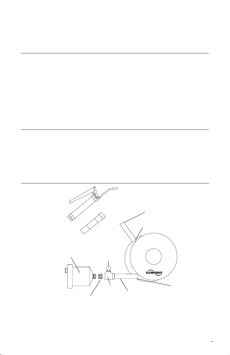
quench cavity. See Figure 1.
Mounting Details
SLD Seal Support System
Figure 1
6.4 mm ID (.25 inch ) x 125 mm (5 inch)
SLD grease gun
SLD grease
cartridge
Auto-Luber Unit
Temporary Plug
used for initial grease
gun lling
SLD
Grease Fitting
Pipe tee
6.4 mm ID (.25 inch) x 460 mm (18 inch)
Minimum pipe diameter and maximum
pipe length
Minimum pipe diameter and maximum
pipe length
Quench Chamber
Outlet Port
Cartridge
Mechanical Seal
End View
Quench Chamber
Inlet Port
1.2 Install INLET piping using 1/4 inch NPT [6.4mm (0.25 inch) minimum pipe ID]
to connect the pipe tee with the hydraulic lube tting to the bottom INLET
quench connection of the seal. The maximum length of pipe from SLD autoluber to INLET quench connection of the seal should be 460 mm (18 inches).
3
Page 4

It is recommended that the shortest possible pipe length be used. The
piping should be installed with good design and minimal bends from the
SLD to the seal. It should be lled with clean grease prior to start up and
vented to make sure no air has been trapped prior to start up.
Additional support to the SLD auto-luber may be required for pipe lengths
over 100mm (4 inch). High vibration levels or improper support of the SLD
auto-luber unit can cause threaded tting fracture or failure. The unit should
be monitored carefully to ensure that it does not experience excessive
vibration caused by pump operation. If vibration is observed due to inadequate support from the piping alone, additional bracing should be used to
support the unit. The bracing should connect directly to the tting near the
SLD auto-luber, not directly to the unit.
The SLD auto-luber should be located so that it will not be impacted during
normal pump operation and maintenance. Excessive or sudden force on
the threaded ttings may lead to a fracture or failure.
Take care using tube ttings or special connectors as they may have an ID
smaller than the 6.4 mm (.25 inch) recommended. Restrictions in the INLET
or OUTLET lines may create back pressure in the system affecting performance of the SLD auto-luber.
1.3 Temporarily plug the pipe tee with a pipe plug prior to initially lling the seal
quench cavity by use of the SLD grease gun.
1.4 Fill the seal quench cavity with SLD synthetic lubricant supplied using
the specied grease gun until lubricant expels from the OUTLET quench
connection located towards the top of the seal. This step does not need to
be repeated later when only replacing an empty SLD auto-luber unit.
1.5 Install OUTLET piping using 1/4 inch NPT [6.4 mm (0.25 inch) minimum
pipe ID] to the OUTLET quench connection of the seal. Piping should have
no restrictions and be a maximum length of 125 mm (5 inch). The piping
should expel the lubricant to a safe location. For dusting or blowing sand
environments, a 90 degree elbow can be connected with the opened end
facing down.
1.6 Remove the pipe plug from the pipe tee and thread the SLD auto-luber unit
in place to nish installation.
1.7 Set the dispensing rate of the SLD auto-luber unit by clicking the
appropriate DIP (direction input postioner) switch or switches located
through the top access port. See Figure 2. It is recommended that the
initial dispensing rate should be between 1-2cc per day (2-3 month setting
for Mini Luber or 8-12 month setting for Jumbo Luber) to start with. Be
sure to also click on the “Blip” light switch. See paragraph 4 Maintenance
for blip light indicators. The visual presence of the blip light every 15 to
20 seconds indicates that the SLD system is functioning and operational.
Be sure to replace the DIP switch access cap and weather proof cover to
protect the SLD auto-luber unit against dust and moisture contamination.
Lubricant dispensing rate may vary depending on atmospheric pressures,
temperatures, and seal size. Please see Section 3 for appropriate
considerations.
4
Page 5

2 Normal Operation
2.1 Once the SLD auto-luber unit is switched on, an electro-chemical reaction
cell is activated that creates inert nitrogen gas. This produces an internal
pressure of up to 345 kPa (50 psi) that expands a bladder that acts against
a piston to force the lubricant out of the dispensing cylinder at a controlled
rate according to the specic time period previously selected. This is an
automatic operation.
2.2 After initial activation, there is a delay before enough nitrogen gas is
generated to start moving the piston to dispense lubricant. The longer the
dispensing period selected the longer the delay before lubricant is dispensed.
See Figure 3. If immediate dispensing is desired, prestart the SLD autoluber unit 12 hours prior to installation by moving all DIP switches to the “On”
position. After this period of time, return all DIP switches to “Off” and reselect
desired dispensing
period. If this step
is not done and all
switches are left
on, then the entire
contents will be
dispensed in only
14 days.
N
I
G
H
1M 2 M 3 M CM 12M B O
O
N
T
OFF
Dispensing
*cc per day
0.25 - 0.3
0.1 - 0.15
*Note that one stroke from a typical hand grease gun is approximately
equal to one cubic centimeter (cc) at normal (101 KPa and 20°C, 14.7
psia and 68°F) atmospheric conditions
Set Dispensing Rate Figure 2
Rate
30 - 32
14 - 15
7 - 8
4 - 5
3 - 4
2.5 - 3
2 - 2.5
1 - 2
1 - 1.4
0.8 - 1
0.7 - 0.8
0.5 - 0.7
125cc Mini Luber
Setting to Empty
Unit Life Switch Setting Unit Life Switch Setting
14 days
123612 B
1 month
123612 B
2 months
123612 B
3 months
123612 B
4 months
123612 B
4.5 months
123612 B
6 months
123612 B
12 months
123612 B
24 months
123612 B
Not Recommended over 24 months
475cc Jumbo Luber
Setting to Empty
14 days
1 month
2 months
3 months
4 months
4.5 months
6 months
8 months
12 months
24 months
123612 B
123612 B
123612 B
123612 B
123612 B
123612 B
123612 B
123612 B
123612 B
123612 B
5
Page 6

Time Delay to Dispense Figure 3
Time Delay to Dispense
Month Switch 1 mo. 2 mo. 3 mo. 6 mo. 12 mo. B
Days Delay 1 2 3 5 10 20
to Start
2.3 If it is desired to decrease or increase the rate of lubricant dispensing after
initial setting, simply click all the DIP switches to “Off” and reselect the new
dispensing period desired.
2.4 To turn off the SLD auto-luber unit during periods of extended equipment
shutdown (months), click all the DIP switches, including the “Blip” light,
to “Off”. Reactivate settings prior to placing equipment back into normal
operation. See paragraph 4 Maintenance for blip light indicators.
3 Dispensing Variations
Variables can be considered when selecting the dispensing rate based on the
operating environment. The SLD auto-luber dispensing rates are based on seal
quench chamber parameters found at normal sea level atmospheric conditions
of 101 kPa and 20°C (14.7 psia and 68°F) and for equipment shaft diameters of
100 mm (4 inch). In general, it is a good practice to rst select a faster dispensing
rate than anticipated and make adjustments based on actual eld observations.
Because of the wide number of variables found with each application, the
following information is being provided only as a guide for making an informed
decision when selecting the appropriate dispensing rate. There is an additive
effect of variables that can cancel or compound with each other. This may help
explain why grease consumption varies between installations, seasons, or from
published rates.
3.1 Altitude Effect
The rate of dispensing will increase at higher altitudes and decrease at lower
altitudes because of the difference in atmospheric pressure acting against
the SLD auto-luber unit. For every change in elevation of 305 meters (1000
feet) from sea level, the discharge rate will naturally increase or decrease
by an additional 5%. For example, at 610 meters (2000 feet) above sea
level, the dispensing rate will be 10% faster. Similarly, at 305 meters (1000
feet) below seal level, the dispensing rate will be 5% slower. Installation
at high altitude may require selection of a slower dispensing rate to help
compensate.
3.2 Temperature Effect
The rate of dispensing will increase at higher temperatures and decrease
at lower temperatures because of the change in lubricant viscosity.
For every change in temperature of 5.5°C (10°F) above or below ambient,
the discharge rate will naturally increase or decrease by an additional 4%.
6
Page 7

For example, at 37°C (98°F), the dispensing rate will be 12% faster.
Similarly, at 9°C (48°F), the dispensing rate will be 8% slower. Installationat
high or low temperature may require selection of a slower or faster dispensing
rate to help compensate.
3.3 Shaft Diameter Effect
The rate of dispensing will need to be increased for large equipment shaft
diameters and can be decreased for small equipment shaft diameters
because of the change in mechanical seal face surface area. For every
change in shaft diameter of 50 mm (2 inch) above or below 100 mm
(4 inch), the discharge rate should be increased or decreased by an additional
3%. For example, a piece of equipment having a shaft diameter of 200 mm
(8 inch), the dispensing rate should be 6% faster. Similarly, for a piece of
equipment having a shaft diameter of 50 mm (2 inch), the dispensing rate can
be 3% slower. Installation for larger or smaller shaft diameters may require
selection of a faster or slower dispensing rate to help compensate and provide
adequate protection from damage to seal faces.
Please contact your Flowserve Sales and Service Representative or Authorized
Distributor for applications at extreme elevations above 3050 meters (10,000 feet)
or atmospheric temperatures above 55°C (130°F) or below -20°C (-4°F) and for
equipment shaft diameters larger than 250 mm (10 inch).
4 Maintenance
The Flowserve SLD Seal Support System components are relatively maintenance
free. Check frequently to be sure that the synthetic lubricant is being expelled by
observing the end of the stand pipe connected to the OUTLET quench chamber
connection and also take notice that the SLD auto-luber is becoming empty.
When the SLD auto-luber is empty, replace with a new one. Never try to rell
the SLD auto-luber or inject lubricant into the grease tting by means of the
grease gun while the auto-luber is installed. There are no user replaceable or
serviceable components located inside of the SLD auto-luber unit itself.
Blip Light Indicators
Flashing Green Light: The system is purging. This means the SLD auto-luber is
functioning but lubricant is not yet being delivered beyond the end of the canister.
Flashing Red Light: The system is functioning normally. The lubricant is now
exiting the SLD auto-luber and is pressurized properly, supplying lubricant at the
current setting.
Steady Red Light: The system battery is dead and the SLD auto-luber is no longer
pressurizing. The SLD auto-luber should be replaced immediately.
No Light: The system is off, or battery is completely dead (if the system switches
are in the “on” position). If the battery is dead, the unit must be replaced.
Steady Red and Green Light: There is a system error. There is an electrical error
in the SLD auto-luber and the unit needs to be replaced.
Note: An empty SLD auto-luber might still have a ashing red light. There is no light
pattern that indicates that the SLD auto-luber is empty. Level must be checked by
a periodic visual inspection on the side of the canister.
7
Page 8

TO REORDER REFER TO
flowserve.com
B/M #
F.O
.
5 Specications
The Flowserve SLD Seal Support System is designed to work best in temperature
environments between minus -20°C (4°F) and plus 55°C (130°F).
Mini Luber dimensions: 117.5 mm high X 79.5 mm diameter
(4.625 inch X 3.125 inch)
nipple 1/4 inch NPT
Mini Luber grease capacity: 125 cc (approximately 4 oz.)
Jumbo Luber dimensions: 168.5 mm high X 120.5 mm diameter
(6.625 inch) X (4.750 inch)
nipple 1/2 inch NPT
Jumbo Luber grease capacity: 475 cc (approximately 16 oz.)
For special problems encountered during installation or for further information
regarding applications outside of specications, contact your nearest Flowserve
Sales and Service Representative or Authorized Distributor.
FIS119eng REV 03/13 Printed in USA
To find your local Flowserve representative
and find out more about Flowserve Corporation,
visit www.flowserve.com
Flowserve Corporation has established industry leadership in the design and manufacture of its products. When properly selected, this
Flowserve product is designed to perform its intended function safely during its useful life. However, the purchaser or user of Flowserve
products should be aware that Flowserve products might be used in numerous applications under a wide variety of industrial service
conditions. Although Flowserve can provide general guidelines, it cannot provide specific data and warnings for all possible applications. The
purchaser/user must therefore assume the ultimate responsibility for the proper sizing and selection, installation, operation, and maintenance
of Flowserve products. The purchaser/user should read and understand the Installation Instructions included with the product, and train its
employees and contractors in the safe use of Flowserve products in connection with the specific application.
While the information and specifications contained in this literature are believed to be accurate, they are supplied for informative purposes
only and should not be considered certified or as a guarantee of satisfactory results by reliance thereon. Nothing contained herein is to
be construed as a warranty or guarantee, express or implied, regarding any matter with respect to this product. Because Flowserve is
continually improving and upgrading its product design, the specifications, dimensions and information contained herein are subject to
change without notice. Should any question arise concerning these provisions, the purchaser/user should contact Flowserve Corporation
at any one of its worldwide operations or offices.
© 2013 Flowserve Corporation
USA and Canada
Kalamazoo, Michigan USA
Telephone: 1 269 381 2650
Telefax: 1 269 382 8726
Europe, Middle East, Africa
Roosendaal, the Netherlands
Telephone: 31 165 581400
Telefax: 31 165 554590
Asia Pacific
Singapore
Telephone: 65 6544 6800
Telefax: 65 6214 0541
Latin America
Mexico City
Telephone: 52 55 5567 7170
Telefax: 52 55 5567 4224
 Loading...