

Page 1

User Instructions SmallFlow 080/081000 - KMENIM8000-01 08/11
®
USER INSTRUCTIONS
Kämmer
®
SmallFlow
™
- Series 080000 / 081000
Low and Micro Flow Valves
FCD KMENIM8001-01 08/11
Installation
Operation
Maintenance
Experience In Motion
1
Page 2
User Instructions SmallFlow 080/081000 - KMENIM8000-01 08/11
STOP!
®
Index
1 Using Kämmer valves and actuators correctly.
2 Unpacking
3 Installation
4 Quick check
5 Maintenance
6 Remove and install actuator
7 Disassemble and assemble valve
1 USING KÄMMER VALVES AND ACTUATORS
CORRECTLY
1.1 General
The following instructions are designed to assist in
unpacking, installing and performing maintenance as
required on Kämmer products. Product users and
maintenance personnel should thoroughly review this
bulletin prior to installing, operating or performing any
maintenance.
In most cases Kämmer valves and actuators are
designed for specific applications (e.g. with regard to
medium, pressure, temperature). For this reason they
should not be used in other applications without first
contacting the manufacturer.
1.2 Terms concerning safety
The safety terms DANGER, WARNING, CAUTION
and NOTE are used in these instructions to highlight
particular dangers and/or to provide additional
information on aspects that may not be readily
apparent.
DANGER: indicates that death, severe personal injury
and/or substantial property damage will occur if proper
precautions are not taken.
WARNING: indicates that death, severe personal injury
and/or substantial property damage can occur if proper
precautions are not taken.
CAUTION: indicates that minor personal injury and/or
property damage can occur if proper precautions are
not taken.
NOTE: indicates and provides additional technical
information, which may not be very obvious even to
qualified personnel.
Compliance with other, not particularly emphasised
notes, with regard to transport, assembly, operation
and maintenance and with regard to technical
documentation (e.g. in the operating instruction,
product documentation or on the product itself) is
essential, in order to avoid faults, which in themselves
might directly or indirectly cause severe personal injury
or property damage.
2
1.3 Protective clothing
Kämmer products are often used in problematic
applications (e.g. extremely high pressures, dangerous, toxic or corrosive mediums). In particular
valves with bellows seals point to such applications.
When performing service, inspection or repair
operations always ensure, that the valve and actuator
are depressurised and that the valve has been cleaned
and is free from harmful substances. In such cases pay
particular attention to personal protection (protective
clothing, gloves, glasses etc.).
1.4 Qualified personnel
Qualified personnel are people who, on account of
their training, experience and instruction and their
knowledge of relevant standards, specifications,
accident prevention regulations and operating
conditions, have been authorised by those responsible
for the safety of the plant to perform the necessary
work and who can recognise and avoid possible
dangers.
1.5 Installation
Before installation check the order-no, serial-no. and/or
the tag-no. to ensure that the valve/actuator is correct
for the intended application.
Do not insulate extensions that are provided for hot
or cold services.
Pipelines must be correctly aligned to ensure that the
valve is not fitted under tension.
1.6 Spare parts
Use only Kämmer original spare parts. Kämmer cannot
accept responsibility for any damages that occur from
using spare parts or fastening materials from other
manufactures. If Kämmer products (especially sealing
materials) have been on store for longer periods check
these for corrosion or deterioration before using these
products. Fire protection for Kämmer products must
be provided by the end user.
1.7 Service / repair
To avoid possible injury to personnel or damage to
products, safety terms must be strictly adhered to.
Modifying this product, substituting nonfactory parts,
or using maintenance procedures other than outlined
in this instruction could drastically affect performance
and be hazardous to personnel and equipment, and
may void existing warranties. Between actuator and
valve there are moving parts. To avoid injury Flowserve
provides pinch-point-protection in the form of cover
plates, especially where side-mounted positioners
are fitted. If these plates are removed for inspection,
service or repair special attention is required. After
completing work the cover plates must be refitted.
Apart from the operating instructions and the
obligatory accident prevention directives valid in the
country of use, all recognised regulations for safety
and good engineering practices must be followed.
Page 3

User Instructions SmallFlow 080/081000 - KMENIM8000-01 08/11
STOP!
STOP!
STOP!
®
WARNING: Before products are returned to Kämmer
for repair or service Kämmer must be provided with
a certificate which confirms that the product has been
decontaminated and is clean. Kämmer will not accept
deliveries if a certificate has not been provided (a form
can be obtained from Kämmer).
1.8 Storage
In most cases Kämmer Products are manufactured
from stainless steel. Products not manufactured
from stainless steel are provided with an epoxy resin
coating. This means that Kämmer products are well
protected from corrosion. Nevertheless Kämmer
products must be stored adequately in a clean, dry
environment. Plastic caps are fitted to protect the
flange faces to prevent the ingress of foreign materials.
These caps should not be removed until the valve is
actually mounted into the system.
1.9 Valve and actuator variations
These instructions cannot claim to cover all details of
all possible product variations, nor in particular can
they provide information for every possible example of
installation, operation or maintenance. This means that
the instructions normally include only the directions to
be followed by qualified personal where the product
is being used for is defined purpose. If there are any
uncertainties in this respect particularly in the event
of missing product-related information, clarification
must be obtained via the appropriate FLOWSERVE
sales office.
2 UNPACKING
2.1 Each delivery includes a packing slip. When unpacking,
check all delivered valves and accessories using this
packing slip.
2.2 Larger valves can be lifted using slings on the yoke
rods or, if present, on the lugs provided for this purpose. If slings are used, attach them so that the outer
tubing or attaching parts are not damaged.
WARNING: If slings are used, be aware that the centre
of gravity of the valve may be above the lifting point. In
this case, secure or support the valve against rotating,
to prevent damage or personnel injury.
2.3 Report transport damage to the carrier immediately.
3 INSTALLATION
3.1 Clean tubing prior to installing.
3.2 If possible, install the valve in an upright position
(actuator on top), to ease maintenance. An upright
installation position is important with low-temperature
applications, in order to keep the distance between
the packing material and the medium as large as possible. The packing material then retains the ambient
temperature as much as possible.
WARNING: Do not insulate extension bonnets that are
provided for hot or cold services
3.3 Make sure that sufficient overhead clearance above
the actuator is maintained, to allow for disassembly
of plug from the valve body (see following table).
Actuator
size
37/47
38/48
Clearance
(mm)
95
140
Actuator
size
P1
P2
Clearance
(mm)
90
140
3.4 After installing, check direction of flow again. The
direction of flow is shown by the arrow on the housing.
3.5 If the valve is to be welded into the line, make sure
that the valve is shielded from excessive heat.
3.6 Connect supply pressure and signal lines. Control
valves are usually supplied with a positioner. The end
connections for supply pressure and signal are clearly
marked. Actuator and positioner are suitable for max.
4.2 bar (60 psi) supply pressure. If the supply pressure
exceeds the pressure specified on the nameplate, a
pressure reducing station is required. If instrument air
is not available, install an oil separator/air filter in the
air inlet line. All connections must be leak free. Please
also observe the User instructions for I/P actuators.
4 QUICK CHECK:
Before operating, check the valve as follows:
4.1 Open and close the valve, and observe the movement
of the actuator stem. The movement must be smooth
and linear.
2.4 In case of discrepancies, contact your nearest
FLOWSERVE sales office.
4.2 Check for maximum stroke through change of signal
(for pneumatic positioners, 0.2 - 1.0 bar or corresponding split-range values; for IP positioners, 4-20
or 0-20 mA).
3
Page 4

User Instructions SmallFlow 080/081000 - KMENIM8000-01 08/11
STOP!
STOP!
®
4.3 Check all air connections for leaks.
4.4 Tighten packing nut (see table 1 )
Torque in Nm
Thread
PTFE Graphit
M20 x 1,5 1 3
M30 x 1,5 6 15
M38 x 1,5 15 35
M45 x 1,5 17 40
Table 1
NOTE: An excessively tightened packing nut can cause
excessive packing wear and can hinder the free movement of the plug stem.
4.5 Check fail-safe position. To do this, close supply pressure and observe whether the valve opens or closes
as defined.
4.6 After use at fluctuating temperatures, re-tighten all bolt
connections and check for leaks.
5 MAINTENANCE
Check valves for correct functioning at regular intervals
(at least once every 6 months) as follows. This check
can be made when installed and in many cases
without interrupting production. If internal defects are
suspected, see section „Disassembly and Assembly of
Valve“.
5.1 Examine gaskets for leaks and if necessary re-tighten
bolts.
5.2 Check bellows gasket and test connection - if present
- for external leaks.
5.3 Check valve for damage caused by corrosive residues
or corrosive vapours.
5.4 Clean valves and if necessary repaint.
WARNING: To prevent a buildup of electrostatic charge
clean the actuator/valve with a damp cloth only.
5.5 Check packing nuts for correct torque (see table 1).
NOTE: An excessively tightened packing nut can cause
excessive packing wear and can hinder the free movement of the plug stem.
5.6 If possible, open and close valve and check for maximum stroke and smooth movement of the plug stem.
Irregular movement of the plug stem may indicate
internal defects.
4
NOTE: With graphite packing, irregular movement of
the plug stem is normal.
WARNING: Keep hands, hair, clothing, etc. away from
all moving parts. Failure to do so can lead to serious
injury.
5.7 Check all accessories for firm seating.
5.8 If possible, close supply pressure and check the failsafe position.
5.9 Check stem boot, if present, for wear.
5.10 Check actuator for leaks. To do this, spray housing,
air connections and plug stem guide with leak spray
and check for any bubble formation.
5.11 Clean plug stem.
5.12 Check air filter, if present, and if necessary replace
insert.
6 REMOVE AND INSTALL ACTUATOR
General Information
We recommend separating the actuator from the
valve during all repair work. However, many maintenance and adjusting operations can be carried out in
an installed condition.
6.1 Remove series 4 actuator
(see Figs 1 + 2)
6.1.1 Disconnect air supply.
DANGER: As poisonous or hazardous mediums may
be present, the system must be depressurized and all
process materials drained. If necessary, decontaminate the valve. Keep hands, hair and clothing well away
from moving parts. Wear face and eye protectors.
Failure to do so can lead to serious injury.
6.1.2 As required remove all tubing.
6.1.3 Remove two coupling screws.
6.1.4 Loosen and remove all yoke rod nuts and carefully lift
off actuator.
6.1.5 Loosen coupling locknut and remove coupling half
and locknut:
NOTE: Never rotate the plug or perform any service
on the valve while the plug is seated in the seat ring.
Doing so may cause irreparable damage to the trim
set. To ensure against this, always hold the plug out
of the seat while working on the valve assembly.
6.2 Install actuator
The actuator stem must be fully extended:
Actuators with air-to open action must be fully vented.
Actuators with air-to-close apply supply pressure.
Manually depress the plug stem to ensure the plug is
fully seated.
Page 5
User Instructions SmallFlow 080/081000 - KMENIM8000-01 08/11
®
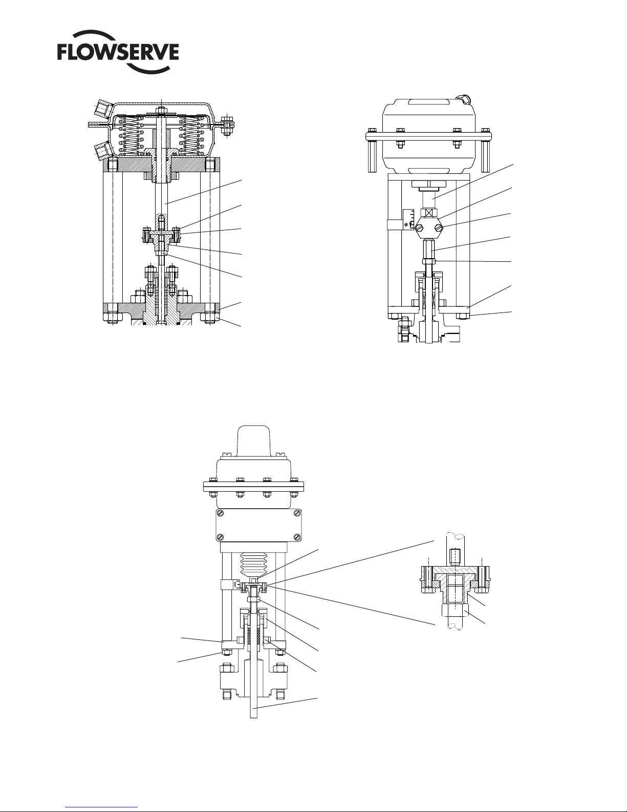
Actuator stem
Actuator stem
Coupling screw
Coupling
Coupling insert
Locknut
Yoke plate
Yoke plate nut
Coupling
Coupling screw
Coupling insert
Locknut
Yoke plate
Yoke plate nut
Actuator series 2, type P1
Fig. 1
Yoke plate
Yoke plate nut
Actuator series 2, Types P2, P3, P4
Actuator stem
Locknut
Gland nut
Slotted nut
Fig. 1a
Coupling insert
Locknut
Coupling
Actuator series 4
Plug stem
Fig. 2
5
Page 6

User Instructions SmallFlow 080/081000 - KMENIM8000-01 08/11
®
Locknut
Packing follower
Packing
Guide bushing
Anti-rotation plate
with retaining screw
Body
Gland nut
Clamp nut
Bonnet
Gasket
Plug stem
Seat ring
6.2.1 Screw coupling insert locknut and coupling insert as
far as possible onto plug stem.
6.2.2 Place the actuator assembly on the valve engaging
the yoke rod threads in the lower yoke plate and
ensuring the actuator faces in the correct direction.
6.2.3 Unscrew the coupling insert until the yoke rods are
raised from the lower yoke plate by around 2 mm.
NOTE: Ensure that the plug assembly is not rotated with
the plug seated. This may cause irreparable damage to
the seating faces.
6.2.4 Coupling for actuator series 2
Refit the coupling, ensuring that the arrows,
embossed on the coupling halve, points upward
towards the actuator, and secure with 2 retaining
screws.
6
Typical valve configuration
Fig. 3
6.2.5 Coupling for actuator series 4
Insert and tighten coupling screws.
6.2.6 Apply supply pressure resp. vent actuator to half
stroke and refit and tighten yoke rod retaining nuts.
6.2.7 Connect all tubing.
7 DISASSEMBLE AND ASSEMBLE VALVE
General Information
We recommend separating the actuator from the valve
during all repair work.
However, many maintenance and adjusting operations
can be carried out in installed condition.
NOTE: Never turn plug or perform any service on as-
sembly while the plug is in the seat ring. Doing so may
cause irreparable damage to the trim set. To ensure
against this, always hold the plug out of the seat while
working on the valve assembly.
7.1 Disassemble valve
7.1.1 Disconnect actuator from valve body
7.1.2 Remove the anti-rotation plate.
7.1.3 Hold the plug out of the seat. Using a 24 mm wrench
Page 7

User Instructions SmallFlow 080/081000 - KMENIM8000-01 08/11
®
loosen and unscrew the bonnet assembly from the
valve.
7.1.4 Carefully remove the plug from the bonnet. Note that
the threaded section of the plug stem is slightly smaller
in diameter than the guided section, this helps prevent
damage to the packing when removing the plug from
the bonnet.
7.1.5 If the packing is to be replaced, remove the existing
packing rings and guide bushing and clean the packing
chamber.
7.1.6 Remove the gasket.
7.1.7 Using a ¼" drive 10 mm socket remove the seat from
the body. Note: The O.D. of some sockets may be too
large to fit inside the valve body, it may be necessary
to turn down the O.D. to fit the body
7.1.8 Clean and inspect all parts.
7.2 Assemble valve
NOTE: All worn or damaged parts must be replaced.
Reusable parts must be clean.
7.2.1 Coat the seat ring with a small amount of lubrication
(process permitting).
7.2.2 Thread the seat into the body and torque to 400 Ncm.
DO NOT OVERTORQUE
7.2.3 Bubble test seat by plugging the seat ring with a pencil
eraser and applying 2 bar to the upstream port of the
valve body. If leakage exists retorque the seat ring and
repeat the bubble test.
7.2.4 Replace the gasket.
7.2.5 Insert the plug into the bonnet. Install the guide bush-
ing into the packing chamber with bevelled end facing
down.
7.2.6 Coat the bonnet threads with a small amount of
lubricant (process permitting). Hold the plug stem
fully retracted in the bonnet and thread the bonnet
assembly into the body. Using a 24 mm torque wrench
torque the bonnet to 80 Nm.
7.2.7 Replace packing by inserting packing rings one at a
time tapping each one down with a suitable bushing.
NOTE: ensure that the gaps in the packing rings are
distributed evenly around the circumferance in the
packing box (gaps not in line).
NOTE: different packings and fitting sequences are
shown in the spare parts list.
7.2.8 Insert packing follower. Fit gland nut for transport
purposes only. Gland nut to be fitted correctly and
tightened down (see table 1) when the actuator is
mounted.
7.2.9 Manually stroke the assembly for alignment. If mis-
aligned, remove the bonnet and repeat the tightening
procedure until proper alignment is achieved.
7.2.10 Refit the anti-rotation plate.
8 Medium temperatures
Bonnet / Extension Packing / Stem Body gasket Bellows seal
Normal design
Normalising fins
extension
Bellows seal
extension
Bellows seal
extension
PTFE
Compound
Graphite Stainless steel N/A
PTFE
Compound
Graphite Stainless steel Graphite
Stainless steel N/A
Stainless Steel
PTFE
Compound
Medium temperature
range
-30 .. 60°C
-30 .. 75°C
-30 .. 110°C
-30 .. 175°C
-30 .. 175°C
-30 .. 60°C
-30 .. 75°C
-30 .. 110°C
-30 .. 175°C
-30 .. 270°C
-30 .. 400°C
-30 .. 60°C
-30 .. 75°C
-30 .. 110°C
-30 .. 175°C
-30 .. 200°C
-60 .. 60°C
-60 .. 75°C
-60 .. 110°C
-60 .. 175°C
-60 .. 270°C
-60 .. 400°C
-196 .. 75°C
-196 .. 100°C
-196 .. 175°C
-196 .. 200°C
Temperatur e
class
T6
T5
T4
T3
T2
T6
T5
T4
T3
T2
T1
T6
T5
T3
T3
T2
T6
T5
T4
T3
T2
T1
T5
T4
T3
T2
7
Page 8

User Instructions SmallFlow 080/081000 - KMENIM8000-01 08/11
®
Germany
Flowserve Essen GmbH
Schederhofstr. 71
45145 Essen
Deutschland
Tel.: +49 (0)201 8919 5
Fax: +49 (0)201 8919 662
USA
Flowserve Corporation
1300 Parkway View Drive
Pittsburgh, PA 15205
USA
Tel.: +1 412 787 8803
Fax: +1 412 787 1944
Singapore
Flowserve Pte Ltd
12 Tuas Avenue 20
Singapore, 638824
Singapore
Tel.: +65 6879 8989
Fax: +65 6862 4940
Contact:
All data subject to change without notice
© 08.2003 Flowserve Corporation. Flowserve and Kämmer are trademarks of Flowserve Corporation
8
 Loading...