

Page 1
SEB
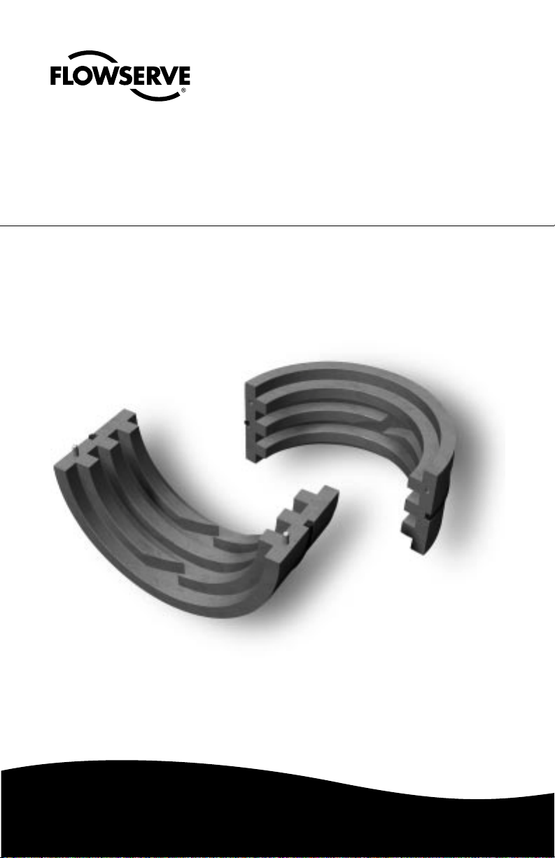
Solids Excluder Bushing
Installation
Instructions
Experience In Motion
Page 2

Description
The Solids Excluder Bushing (SEB) is an engineered device specifically designed to extend
the mean time between failure (MTBF) of a mechanical seal. Pumps that operate with
standard bore seal chambers (packing boxes) tend to accumulate solids from the pumpage in
the seal chamber. Over time, the accumulated solids in the seal chamber can cause
component clogging, erosive or abrasive wear, and seal face overheating. Seal chambers are
commonly flushed with an external clean fluid to help reduce seal damage, however flush
rates come at the expense of additional resources and maintenance. When an SEB is
installed in the throat of a seal chamber, it transfers solids from the seal chamber to the
pumpage, leaving behind a clean environment for the mechanical seal. Removing solids from
the seal chamber reduces seal component erosion, shaft sleeve wear, and seal hang-up
resulting in greater reliability of the mechanical seal.
Installation according to the following steps will assure long trouble free life of the SEB.
1 Equipment Check
1.1 Follow plant safety regulations prior to equipment disassembly:
• lock out motor and valves.
• wear designated personal safety equipment.
• relieve any pressure in the system.
• consult plant Material Safety Data Sheet (MSDS) files for hazardous material
regulations.
1.2 Disassemble equipment in accordance with equipment manufacturer’s instructions to
allow access to seal installation area.
1.3 Remove existing mechanical seal and bushing or compression packing and
packing gland.
1.4 Make sure the bore of the seal housing is clean and free of burrs, cuts, dents, or
corrosion that might inhibit proper seating of the SEB at the throat of the seal housing.
1.5 Check equipment dimensions and Shaft Rotation. They must agree with the
dimensions shown in Figure 1 and the assembly drawing supplied with the SEB. Critical
dimensions include the shaft OD (A), the seal chamber bore (B) and the chamber
depth (C).
1.6 Handle SEB with care, it is manufactured to precise tolerances.
Seal Chamber Requirements Figure 1
C
Note: The equipment shaft
rotation direction is critical to
the performance of the SEB and
should be confirmed prior to
installation
A
Shaft or sleeve OD to
be ±0.001 inch (0.03mm) of
nominal and runout with
0.005 inch (0.13mm) FIM
Seal housing ±0.005 inch
(0.13mm) of nominal bore,
have a √125 µ inch (3.2 µm)
R
finish or better and be
a
concentric to shaft within
0.005 inch (0.13mm) FIM
2
© Copyright 2005 Flowserve Corporation
B
Minimum Depth of Chamber = 0.5 inch
(12.7mm) plus seal extension into seal
chamber plus length of SEB
• Shaft Rotation viewed from mechanical seal end.
• Bearings must be in good condition.
• Maximum dynamic shaft deflection at SEB
0.010 inch (0.25mm) FIM
Page 3

2 SEB Installation
2.1 No tools are required for installation.
2.2 Lightly lubricate O-ring G
2.3 Remove warning tape from OD of the SEB
Note:
After the warning tape has been removed, the SEB can be separated into two halves.
Care must be taken when handling the SEB after removing this tape, in order to
assure the individual halves do not separate unintentionally.
2.4 Align each individual half of the SEB
around the shaft by engagement of the
alignment pins.
2.5 While compressing the OD of the SEB
gently slide the assembly into the seal
chamber bore and fully seat the SEB against
the throat restriction. See Figure 2. Note the
SEB can be installed in either direction
inside its target seal chamber.
Caution:
Not fully seating the SEB against
the throat restriction may result in
SEB contact with the mechanical
seal rotating components,
therefore, resulting in damage and
performance degradation of the
SEB or the mechanical seal.
2.6 Complete the seal installation and
equipment assembly. The SEB
performance is enhanced with a clean
fluid flush. The recommended flush
should be from a clean external source
(Plan 32). Connect the flush line and
follow operational recommendations.
See Figure 3.
3 Operational Recommendations
SEB Figure 2
G
T ypical Seal Gar d Figure 3
Pressure gauge
Clean-out port
Supply flow
control valve
To gland flush tap,
flush mixes with
pumped fluid
50
PSI/kPa
100
™
Seal Gard
Flow tube
I
O
2
20
O
2
LPM H
GPH H
10
30
15
4
Check
®
Flow Solutions Division
Durametallic
valve
Float
Flow Reading
On/off supply valve
Single Flowserve Seal
Alarm probe
option
Supply of Clean
Flush
3.1 Do not exceed corrosion limits. The SEB is designed to resist corrosion by most
chemicals. However, do not expose the SEB materials of construction to products
outside of their corrosion limits. Consult your Flowserve Representative for chemical
resistance recommendations.
3.2 Do not exceed the recommended temperature limits of 32° to 250° F (0 to 121° C).
3.3 Do not exceed the speed limits of 10 to 80 fps (3-25 m/s).
3.4 Seal chamber should be flooded and properly vented prior to pump start up.
For special problems encountered during installation, contact your nearest Flowserve Sales
and Service Representative or Authorized Distributor.
3
Page 4

TO REORDER REFER TO
B/M #
.
F.O
4 Repair
The SEB can not be reconditioned and must be replaced if damaged. The SEB is designed to
provide reliable operation under a wide range of operating conditions.
The design and dimensional tolerances are critical to its performance. Only parts supplied by
Flowserve should be used when replacing this device. These parts are available from
numerous Flowserve stocking locations. When ordering replacement parts refer to the SEB
assembly part code.
If the SEB must be returned, a signed certificate of decontamination must be attached. An
MSDS must be enclosed for any product that came in contact with the device.
USA and Canada
Flowserve Corporation
Flow Solutions
Kalamazoo, Michigan USA
Telephone: 1 269 381 2650
Telefax: 1 269 382 8726
FIS171 1-05 Printed in USA
To find your local Flowserve representative
and find out more about Flowserve Corporation,
visit www.flowserve.com
Flowserve Corporation has established industry leadership in the design and manufacture of its products. When properly
selected, this Flowserve product is designed to perform its intended function safely during its useful life. However, the
purchaser or user of Flowserve products should be aware that Flowserve products might be used in numerous applications
under a wide variety of industrial service conditions. Although Flowserve can provide general guidelines, it cannot
provide specific data and warnings for all possible applications. The purchaser/user must therefore assume the ultimate
responsibility for the proper sizing and selection, installation, operation, and maintenance of Flowserve products. The
purchaser/user should read and understand the Installation Instructions included with the product, and train its employees
and contractors in the safe use of Flowserve products in connection with the specific application.
While the information and specifications contained in this literature are believed to be accurate, they are supplied for informative
purposes only and should not be considered certified or as a guarantee of satisfactory results by reliance thereon. Nothing
contained herein is to be construed as a warranty or guarantee, express or implied, regarding any matter with respect to this
product. Because Flowserve is continually improving and upgrading its product design, the specifications, dimensions and
information contained herein are subject to change without notice. Should any question arise concerning these provisions, the
purchaser/user should contact Flowserve Corporation at any one of its worldwide operations or offices.
flowserve.com
Europe, Middle East, Africa
Flowserve Corporation
Flow Solutions
Roosendaal, The Netherlands
Telephone: 31 165 581400
Telefax: 31 165 552622
Asia Pacific
Flowserve Corporation
Flow Solutions
Singapore
Telephone: 65 684 65100
Telefax: 65 674 71963
Latin America
Flowserve Corporation
Flow Solutions
Mexico City
Telephone: 52 55 5567 7170
Telefax: 52 55 5567 4224
 Loading...