

Page 1
Experience In Motion
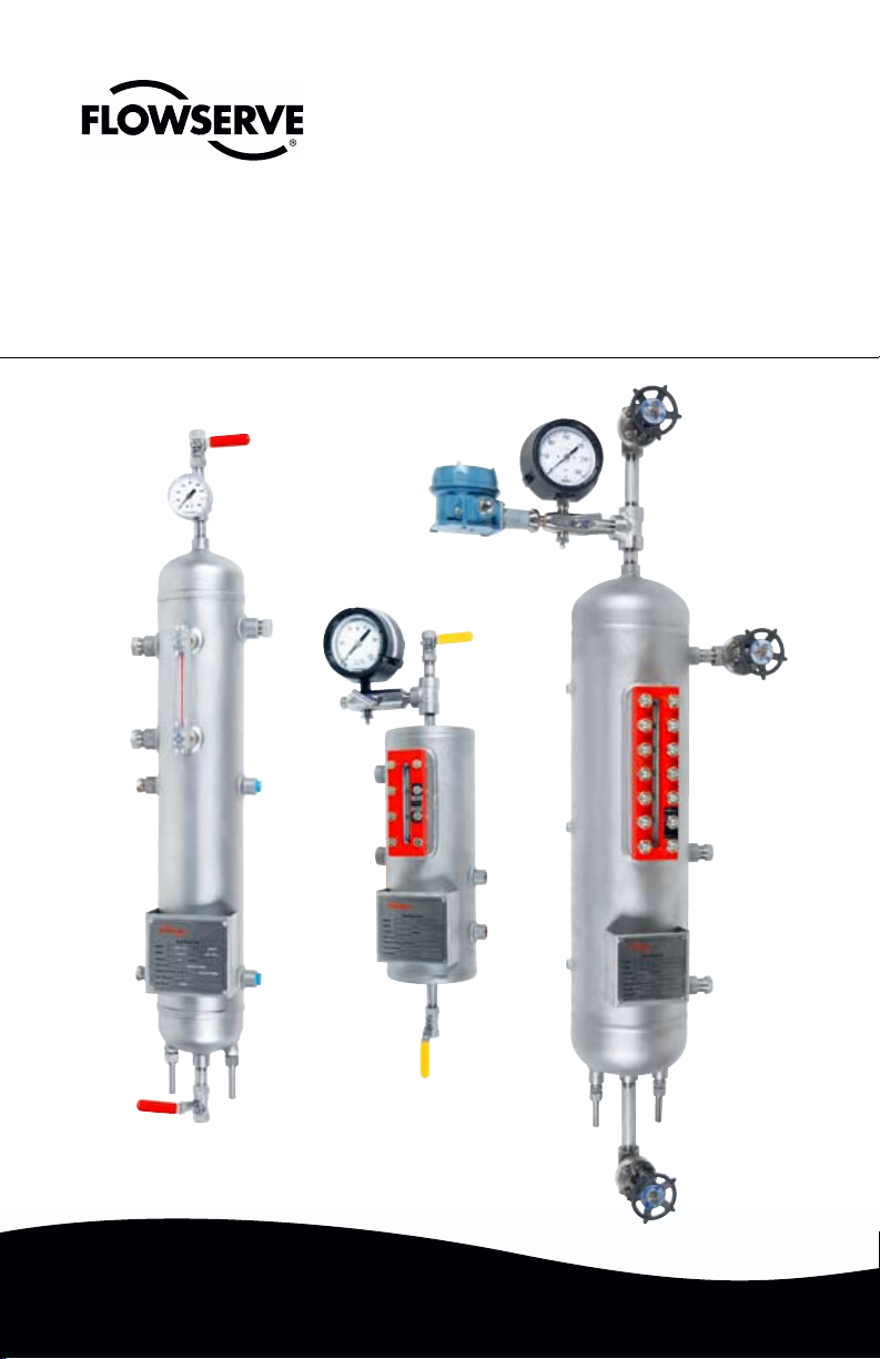
Seal Support Reservoir
Flowserve seal support system for dual
unpressurized and dual pressurized operation
Installation
Instructions
Page 2

Introduction
This manual covers the installation and operation of Flowserve Seal Support
Systems for dual unpressurized (API Plan 52/ANSI Plan 7352) and dual
pressurized seals (API Plan 53A, 53B, 53C/ANSI Plan 7353). The following
instructions describe the appropriate system, buffer/barrier uids, installation,
start-up and maintenance.
Reservoir
The standard supply tank is designed in accordance with ASME Code Section VIII,
Division 1. All tanks are welded in accordance with ASME Code Section IX. Tanks
include inlet, outlet, vent and ll, along with mounting lugs as minimum connection.
Sealing System Description
Supply tank assemblies can be used as reservoirs for dual seal designs. The
sealing system produced is dened as being either a thermal convection system
or a forced circulation system.
Support System Descriptions
API Plan 53A, 53B, 53C/ANSI Plan 7353A for dual pressurized seals
An API Plan 53A/ANSI 7353A is a pressurized dual seal system which is used
in services where no process leakage to atmosphere is tolerated. The system
consists of dual mechanical seals with a barrier uid between them. The barrier
uid in the supply tank is pressurized to a higher pressure than the seal chamber,
normally 15 to 25 psig (1 to 1.7 bar). Primary (inboard) seal leakage will be barrier
uid into the product. A small amount of leakage is customary.
An API Plan 53A/ANSI Plan 7353A is usually chosen over an API Plan 52/ ANSI
Plan 7352 for dirty, abrasive or polymerizing products which would either damage
the seal faces or cause problems with the barrier uid system if an API Plan 52/
ANSI Plan 7352 is used. There are two disadvantages to an API Plan 53A/ANSI
Plan 7353A which must be considered. First, there will always be some leakage
of barrier uid into the product. Normally, this leakage will be minute, and the
leakage rate can be monitored via the level gauges or other instrumentation.
However, the product must be able to accommodate a small amount of contami-
nation from the barrier uid. Secondly, an API Plan 53A/ANSI Plan 7353A system
is dependent on having the supply tank pressure maintained at the proper level.
If the supply tank pressure drops, seal leakage direction will be reversed and the
barrier uid will be contaminated with the process uid.
An Induced Circulation System is essentially the same as the thermal convection system, except for the addition of a circulating device in the seal cavity which
provides for positive ow in the system. The addition of the circulating device
provides for positive ow of barrier/buffer uid shown in Figure 1. Because supply
tanks provide for poor radiation and convection of heat to the atmosphere, it is
common to add cooling coils inside the reservoir as a means of removing heat.
2
© Copyright 2008 Flowserve Corporation
Page 3

Dual Inside Seal with Induced Circulation
Pressure source
4 feet (1.2 m)
maximum
1.5 - 2 feet
(0.45 -0.6 m)
minimum
Orifice
option
Bypass line
from pump
discharge
Supply
tank
assembly
normally open
Level switch (low)
Pressure
switch
(low)
Pressure
indicator
Cooling
coils
Drain
normally
closed
Through Supply Tank with Cooling Coil Figure 1
Plan 53A/ANSI Plan 7353A
What
Pressurized barrier uid circulation
through reservoir.
Fluid is circulated by a pumping ring
in the dual seal assembly
Why
Isolate process uid
Zero process emissions
Typically used <150 psig (10.3 bar) pressure
Plan 53B/ANSI Plan 7353B
What
Pressurized barrier uid circulation
with bladder accumulator.
Fluid is circulated by a pumping ring in
the dual seal assembly.
Why
Isolate process uid.
Zero process emissions.
Higher pressure than Plan 53A.
Plan 53C/ANSI Plan 7353C
What
Pressurized barrier uid circulation with
piston accumulator.
Fluid is circulated by a pumping ring in
the dual seal assembly.
Why
Isolate process uid.
Zero process emissions.
Higher pressure than Plan 53A.
Dynamic tracking of system pressure.
3
Page 4

API Plan 52/ANSI Plan 7252 for dual unpressurized seals
4 feet (1.2 m)
maximum
1.5 - 2 feet
(0.45 -0.6 m)
minimum
Orifice
option
Bypass line
from pump
discharge
Supply
tank
assembly
Level switch (high)
Level switch (low)
Pressure
switch
(high)
Pressure
indicator
Cooling
coils
Drain
normally
closed
To flare
or vapor
recovery
An API Plan 52/ANSI Plan 7352 is an unpressurized dual seal system which
is used in services where no leakage to atmosphere is tolerated. The system
consists of dual mechanical seals with a buffer uid between the seals. The
buffer uid is contained in the seal pot which is vented to a are, thus maintaining
the buffer uid pressure close to atmosphere. Primary (inboard) seal leakage will
be product leakage into the buffer uid. There will always be some leakage.
An API Plan 52/ANSI Plan 7352, Figure 2, works best with clean, non-polymeriz-
ing products which have a vapor pressure higher than the buffer uid pressure.
These products will ash in the supply tank and the vapor can escape to the vent
system. If the product has a vapor pressure lower than the buffer uid or supply
tank pressure, the leakage will remain a liquid and will cause the barrier uid level
to rise.
Should excessive primary (inboard) seal leakage not be detected early, the
heavier process uid will displace the buffer uid and can result in increased
seal wear.
Dual Unpressurized Seal with Induced Circulation
Through Supply Tank with Cooling Coils Figure 2
API Plan 52/ANSI Plan 7352
4
Page 5

Buffer/Barrier Fluid Selection
The following should be considered when selecting a barrier/buffer uid:
• Compatibility of the uid with the process pumpage being sealed so as not to
react with or to form gels or sludge when the uids are intermixed.
• Compatibility of the uid with the metallurgy, elastomers and other
materials of the seal/ush system construction.
For an API Plan 53A/ANSI Plan 7353A pressurized barrier uid system where
the method of pressurization is a gas blanket, special attention must be given to
the application conditions and barrier uid selection. Gas solubility in the barrier
uid increases with the rising temperature and pressure. As pressure is relieved
or temperatures cool, the gas is released from the solution and may result in
foaming and loss of circulation of the barrier uid. This problem is normally seen
where higher viscosity barrier uids, such as lube oils, are used at pressures
above 150 psig (10.3 bar). Synthetic barrier uids offer greater compatibility and
wider operating ranges where traditional uids have problems.
The viscosity of the barrier/buffer uid should be checked over the entire
operating temperature range with special attention being given to start-up
conditions. The viscosity should be less than 500 cst at the minimum
operating temperature.
1. For services above 50°F (10°C), hydrocarbon barrier/buffer uids having a
viscosity below 100 cst at 100°F (37.8°C) and between 1 and 10 cst at
212°F have demonstrated proper operating climate.
2. For services below 50°F (10°C), hydrocarbon barrier/buffer uids having a
viscosity between 5 and 40 cst at 100°F (37.8°C) and between 1 and 10 cst
have demonstrated proper operating characteristics.
3. For aqueous streams, mixtures of water and ethylene glycol or propylene
glycol are usually adequate. Commercially available automotive antifreeze
should never be used. The additives in antifreeze tend to plate out (leave a
residue) on seal parts and cause failure as a result of gel formation.
Note: Ethylene glycol may be considered a hazardous material and/or
hazardous waste when used as a barrier uid.
4. The uid should not freeze at the minimum site ambient temperature.
5
Page 6

Fluid volatility and toxicity of the uid must be such that the leakage to the
atmosphere or disposal does not impose an environmental problem.
1. The uid should have an initial boiling point at least 50°F above the
temperature to which it will be exposed.
2. The uid should not have a ash point higher than the service temperature
if oxygen is present.
The uid should be able to meet the minimum 3-year continuous seal operation
criteria without adverse deterioration. It should not form sludge, polymerize or
coke after extended use.
1. For hydrocarbon streams, parafnic-based high purity oils having little or no
additives for wear/oxidation resistance or synthetic based oils have been
used successfully.
2. Anti-wear/oxidation-resistant additives in commercial turbine oils have been
known to plate out on seal faces.
Installation
1. The reservoir is mounted vertically not more than 3 feet (0.9 meters) from
the seal gland to the vertical centerline of the reservoir. The bottom of the
reservoir is mounted 18 to 24 inches (45.7 to 61 centimeters) above the
horizontal centerline of the pump.
2. It is highly recommended that the reservoir be ushed with clean uid prior
to equipment start-up to remove any foreign matter from the system.
3. All lines from the seal cavity to the reservoir must slope upward at all points.
The upward slope should be a minimum of 1/4 inch per foot with all bends
being large radius. The minimum size for tubing should be 3/4 inch
diameter. Tubing is recommended.
4. Connect the supply connection (lower seal connection on the reservoir)
to the bottom (inlet) gland connection (BI - inlet).
5. Connect the return connection (upper seal connection on the reservoir)
to the upper (outlet) gland connection (BO - outlet).
6. If the reservoir is equipped with cooling coils, connect water lines to the coil
connections on the bottom of the reservoir.
7. Remove all plastic shipping plugs and properly seal or attach piping
with metal connections.
8. Connect wiring to any instruments included with the system such as a
pressure switch/transmitter or level switch/transmitter.
6
Page 7

9. If the system is equipped with a weld pad level gauge the bolts on the cover
should be retorqued to 20 ft/lbs. (Tighten in 5 ft/lb increments starting with
the center bolts and working out.)
10. Connect vent connection to are or vapor recovery system (Plan 52).
Do not open vent valve until reservoir has been lled with buffer uid.
11. Fill reservoir with barrier/buffer uid to the middle of the sight glass.
Gas volume of the system should be at least 25 percent of the reservoir
volume to allow for thermal expansion during operation.
12. Before starting the system, bleed all air from highest point in the system.
13. Connect external pressurization to reservoir on Plan 53A, B, C (dual seal).
A pressure regulator and check valve are required to maintain a constant
pressure on the system. The pressure in the reservoir should be maintained
at least 25 psi (1.7 bar) above the seal cavity pressure.
Make sure reservoir is lled before pressurizing.
Start-Up
1. API Plan 52/ANSI Plan 7352 - open the valve to the vent or are system slowly.
2. API Plan 53A, B, C/ ANSI 7353 - slowly open the valve between reservoir
and external pressurization source. Slowly increase the pressure to avoid
gas ingestion. Check for leaks as unit is being pressurized. Operating
pressure is normally 15 to 25 psig (1 to 1.7 bar) above seal cavity pressure
depending on seal design. The pressure gauge on system can be used to
monitor system pressure.
3. If system is equipped with cooling coils, open the valve to allow water to ow
through coils.
4. The pump can now be commissioned for start-up per the equipment
manufacturer's recommendations and all plant safety and start-up
procedures.
Maintenance
During planned plant shutdowns, it is recommended maintenance practice that the
buffer/barrier uid be drained, reservoir ushed and new uid put in the reservoir.
This will ensure the quality of the buffer/barrier uid used to lubricate the seals and
help remove any particles that may have accumulated in the reservoir.
When changing or cleaning the glass on armored sight gauges (weld pad level
gauge), always install new gaskets and retorque bolts to proper amount. It is also
recommended that the bolts be checked and retorqued prior to rst operation.
They can come loose during shipping and transport.
7
Page 8

FIS123eng REV 11/08 Printed in USA
flowserve.com
USA and Canada
Tulsa, Oklahoma, USA
Telephone: 1 918 599 6062
Telefax: 1 918 583 1071
Europe, Middle East, Africa
Essen, Germany
Telephone: 49 201 31937-0
Telefax: 49 201 2200-561
Asia Pacific
Singapore
Telephone: 65 6544 6800
Telefax: 65 6214 0541
Latin America
Mexico City
Telephone: 52 55 5567 7170
Telefax: 52 55 5567 4224
TO REORDER REFER TO
B/M #
F.O
.
To find your local Flowserve representative
and find out more about Flowserve Corporation,
visit www.flowserve.com
Flowserve Corporation has established industry leadership in the design and manufacture of its products. When
properly selected, this Flowserve product is designed to perform its intended function safely during its useful life.
However, the purchaser or user of Flowserve products should be aware that Flowserve products might be used
in numerous applications under a wide variety of industrial service conditions. Although Flowserve can provide
general guidelines, it cannot provide specific data and warnings for all possible applications. The purchaser/user
must therefore assume the ultimate responsibility for the proper sizing and selection, installation, operation, and
maintenance of Flowserve products. The purchaser/user should read and understand the Installation Instructions
included with the product, and train its employees and contractors in the safe use of Flowserve products in connection
with the specific application.
While the information and specifications contained in this literature are believed to be accurate, they are supplied for
informative purposes only and should not be considered certified or as a guarantee of satisfactory results by reliance
thereon. Nothing contained herein is to be construed as a warranty or guarantee, express or implied, regarding any
matter with respect to this product. Because Flowserve is continually improving and upgrading its product design,
the specifications, dimensions and information contained herein are subject to change without notice. Should any
question arise concerning these provisions, the purchaser/user should contact Flowserve Corporation at any one of
its worldwide operations or offices.
© Copyright 2008 Flowserve Corporation
 Loading...