

Page 1
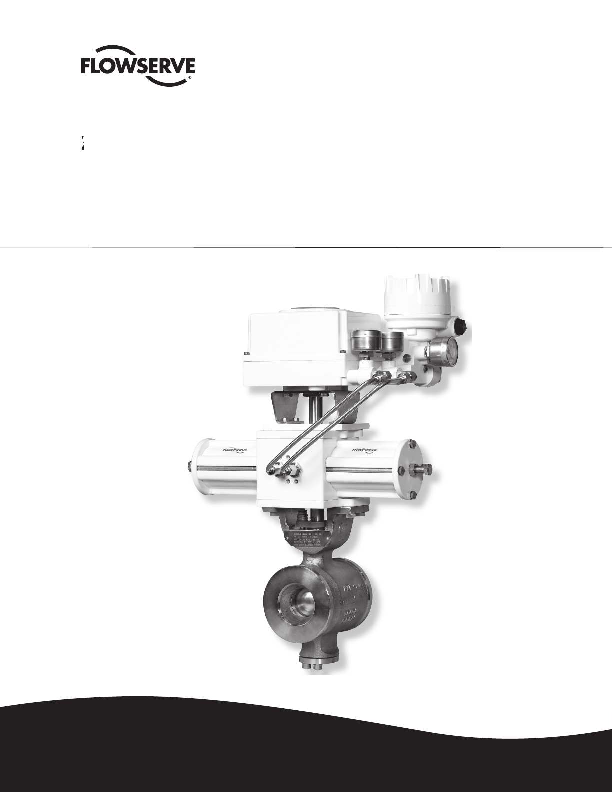
Segmented V-port Ball Valves
FCD VLENIM4152-01 07.09
USER INSTRUCTIONS
Experience In Motion
Page 2
Contents
General 1
Lifting 2
Receiving inspection 3
Installation 4
Flange gaskets 5
Starting up 6
List of materials and spare parts 7
Ordering of spare parts 8
Maintenance 9
To remove the valve from the pipework 9.1
To inspect the ball sector and seat ring 9.2
To inspect and replace the upper shaft
seal of Safeguard type 9.3
To inspect and replace the upper shaft
seal of ZebraCL™ type 9.4
To change the gasket at the lower stem 9.5
Fitting the actuator to the valve 10
1. General
The instructions and list of spare parts are applicable to
ShearStream SB ball sector valves in accordance with
catalogue sheet FCD NFEETB4152-01.
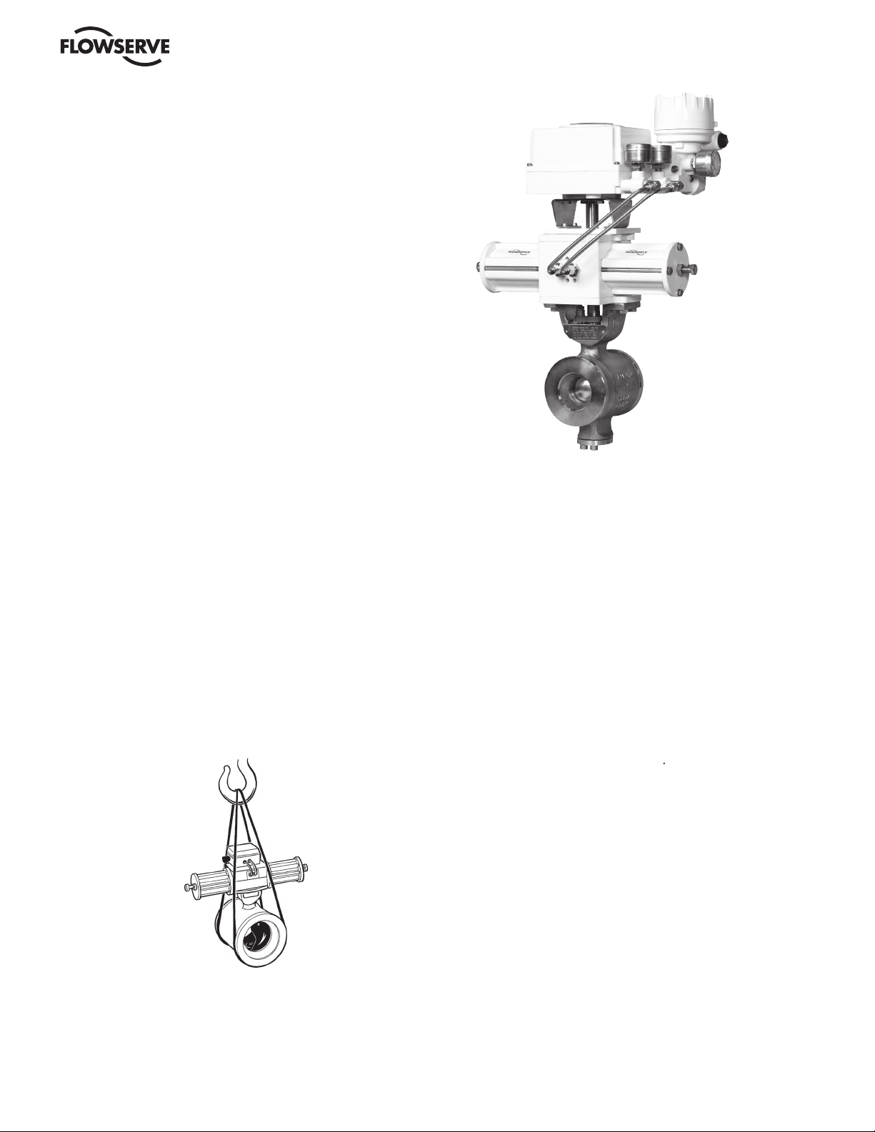
2. Lifting
All lifting must be carried out on the valve itself and not
on the actuator. The joint between the valve and the actua-
tor is designed for carrying the operating torque and the
weight of the actuator - see Fig. 1.
Fig.1 Lifting of the valve
3. Receiving Inspection
All valves leaving our plant are inspected and tested in
accordance with the relevant requirements or in accor-
dance with the requirements specifi ed by the purchaser.
Valves equipped with actuators are subject to functional
testing and are adjusted in such a manner that every unit
during transport, it is advisable that receiving inspection
We would suggest the following inspection procedure:
- Check that
the valve delivered is correct in
terms of type, size, equipment
- Examine the valve, actuator and valve positioner
regarding possible damages
Page 3
3
4. Installation
the pipework is
free from impurities
the valve is to be installed are parallel and are correctly
aligned, and that the distance between the pipe ends
corresponds to the valve length, including gaskets.
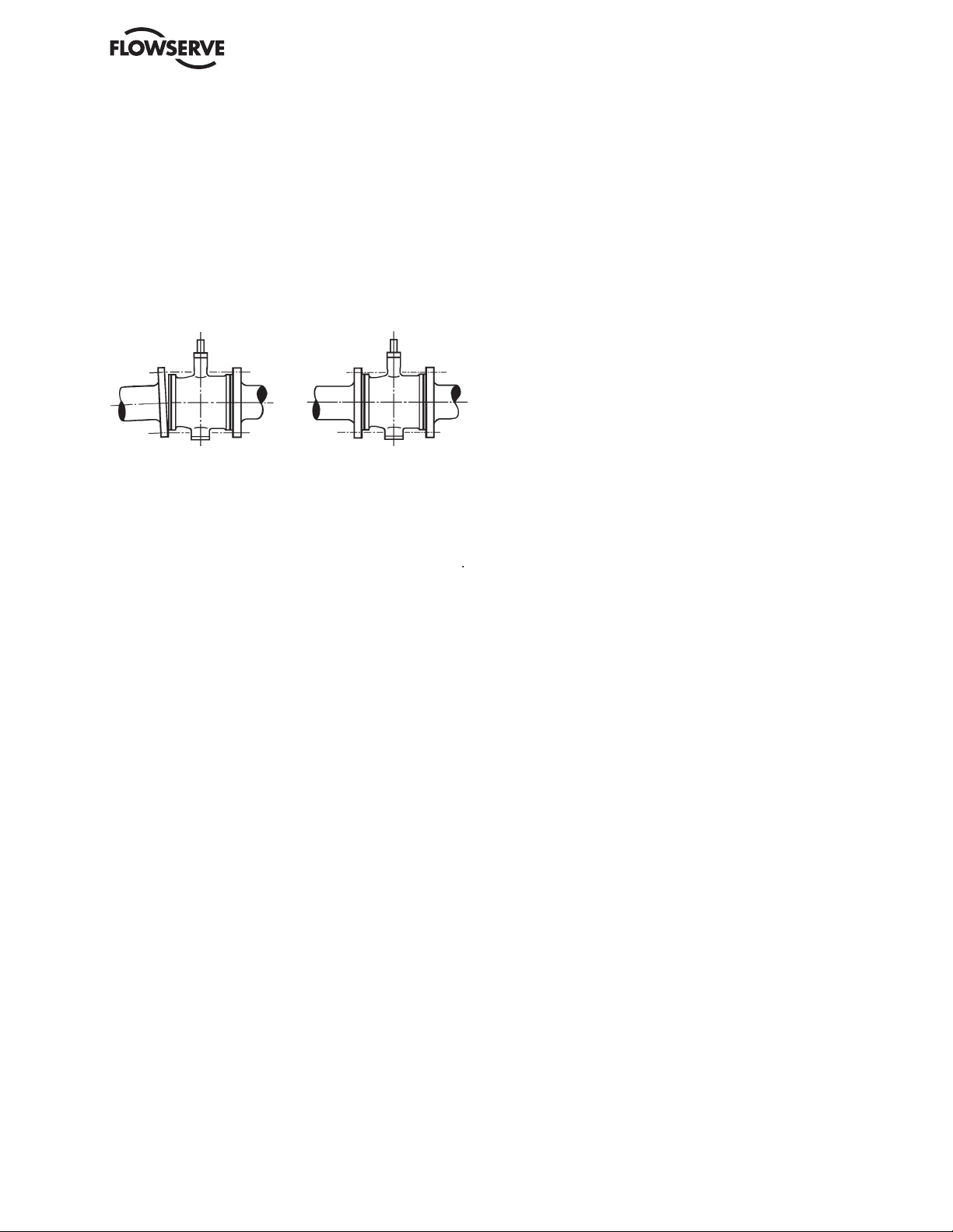
The
valve could not be used for forcing together or aligning
as this will cause loads on the valve
and pipe which may lead to diffi cult damages during
operation. See Fig. 3.
Wrong installation Correct installation
ShearStream SB
valves can be installed in any position
opposite direction.
We also recommend that the valve is mounted with
the stem pointing vertically upwards when the valve is
The pipes should be supported on each side of the
valve
vibrations.
for
with a pneumatic actuator and valve positioner.
5. Flange Gaskets
Gaskets with sizes according to ANSI B16.5, Table E1
6. Starting up
damage the sealing surfaces of the valve and impede its
operation will be fl ushed away.
Page 4

2
29
20
6
4
4
22
3
23
30
33
31
34
32
Fig. 4. ShearStream SB - spare parts, types of stem sealings and seat rings
Seat ring
Stem sealing
13
13
13
9
22
8
5
5
1
1
8
9A
21
Zebra-CL
Safeguard
Metal
Soft
Item
Qty
Part
Material
1
1
EN1.4408/CF8M
1
1
EN1.0619/WCB
2
1
EN1.4408/CF8M HCP
EN1.4408/CF8M
3
Stem, upper
EN1.4460
Stem, lower
EN1.4460
5
1
Gland cover
EN1.4408/CF8M
6
1
EN1.4408/CF8M
7
1
Gasket
Graphite
81EN1.4436
9
EN1.4460
10
Wave spring
EN1.4436
Seat ring
Alloy 6
12
1
Seat seal
13
1
O-ring
FPM
14
1
17
2
Screw
A4
18
19A
Safeguard
V-ring PTFE liveloaded
19B
Zebra-CL
V-ring PTFE
20
4
A4
21
1
Cap spring
EN1.4310
22
1
Steel
23
1
SS
26
Washer
Thread insert
Stainless
28
29
1
Seat ring/Back-up ring
30
1
Stem bearing
Metaloplast
31
1
Stem bearing
Metaloplast
321Washer
A4
33
Cylindrical pin
EN1.4460
34
Washer
Metaloplast
7. List of Materials and Spare Parts
8
9
9
8
27
28
26
2
Page 5

5
8. Product code for important spare parts and spare parts sets
8.1 Ordering of Spare Parts
When placing orders for spare parts, specify:
specifi ed on the identifi cation plate of the valve.
2. Description of the part, its item No. or spare
parts set number, and the quantity required.
Ordering example
or
9. Maintenance
to impurities in the pipework or for some other reason, or
decisive importance
to the entire
any faults should immediately be corrected
9.1 To remove the valve from the pipework
The procedure for inspection and maintenance, for
which no special tools are necessary, is as follows:
also the gaskets - important - for the pipe
fl anges are available.
2. Close the valve.
3. Shut off all compressed air connections
and isolate all electrical connections to the
actuator.
4. Disconnect all compressed air lines and electric
cables connected to the actuator.
5. Release the fl anged joint between the valve
and the pipework. Then lift out the valve. Don’t
use the actuator for lifting.
Apply all lifting
forces to the valve itself and not to the actuator
- see fi g. 1.
which is shown by an
arrow on the valve body.
9.2 To inspect the ball sector and seat ring
section 9.3, items 1 and 2.
2. Remove the indicating pin (23 - fi g. 4).
3. Turn the ball sector through more than 90°, until
it is no longer in contact with the seat ring.
4. Push the seat ring out of its seat at the valve
body inlet. Withdraw it past the ball sector -
between the ball sector and the inside
of the valve body - towards the outlet, and
remove it from the body.
Set or detail
Stem sealing set
Seat ring set
Other spare parts
Type
Zebra CL
Safeguard
Alloy 6
PTFE
Item No
19A
19B
11, 12
12, 29
7
10
DN
25
349 08 050
349 25 540
349 08 080
349 17 460
348 88 295
333 98 460
0040
349 08 050
349 25 540
349 08 08
349 17 46
348 88 295
333 98 46
0050
349 08 050
349 25 540
349 08 08
349 17 46
348 88 295
333 98 46
0065
349 08 050
349 25 540
349 06 089
349 17 469
348 88 295
333 98 46
9
0080
349 08 050
349 25 540
349 08 08
3
349 17 46
3
348 88 29
333 98 46
3
0100
349 08 050
349 25 540
349 08 08
4
349 17 46
4
348 88 29
4
333 98 46
4
0150
349 08 05
349
25 500
349 08 08
5
349 17 46
5
348 88 29
0
333 98 46
5
0200
349 08 05
349 25 720
349 08 08
6
349 17 46
6
348 88 29
333 98 46
6
0250
349 08 05
3
349 25 760
349 08 08
7
349 17 46
7
348 88 29
2
333 98 46
7
0300
349 08 05
349 25 140
349 08 08
8
349 17 46
8
348 88 29
3
333 98 46
8
0350
349 25 180
349
349 20 030
349 15 260
333
00 430
0400
349 25 180
349
7 431
349 20 03
349 15 260
333 00 431
0500
349 25 180
349
7 432
349 20 03
2
349 15 26
333
00 432
Page 6

6
5. Remove the compression spring (10) in the
same way.
6. Carefully wash all parts with warm water and
then, if necessary, with a suitable solvent. Never
scrape the sealing surfaces with hard tools.
7. Examine the surface of the ball sector (2).
Remove any deposits and clean the ball sector
as described in item 6 above.
sur
face of the ball sector.
8. Inspect the seat ring (11) and clean it as
described in item 6 above.
9. Inspect the sealing ring (12) - it need not be
removed from its groove in the body. Fit a new
sealing ring if the original one is damaged.
lubricant, such as Molykote Paste U, Gleitmo
700 or similar.
with a silicone-base grease, such as Silicone
grease DC 111, Silicone grease TKM 1011 or
similar.
Turn the ball sector (2) until it is in contact with
seat ring (11). Use a soft object to press the
seat ring towards the compression spring (10)
to enable the ball sector to move into its proper
position. Continue turning the sector to the
closed position.
pin is to restrict the travel of the ball segment
to 95 - 100°, so that it will always remain in
contact with the seat ring.
9.3 To inspect and replace the upper shaft seal of
Safeguard type
The stuffi ng box usually requires inspection and adjust-
After a certain period of time in service, it may some-
times also be necessary to replace the packing.
Begin by removing the valve positioner. This
can easily be done after the plastic cover of the
valve positioner has been removed. Remove the
four bolts securing the valve positioner to the
actuator. Then remove the nuts securing the
actuator to the valve mounting plate and dismantle
the actuator.
2. Remove the key.
3. Remove the nuts (18). Remove the gland (5).
Then remove the packing (19).
4. Clean the surfaces of the stem, gland (5) and
packing area in the valve body.
5. Carefully examine the surface of the stem which
must be completely free from marks and
scratches.
6. Grease the stem with a suitable grease, such as
Silicone grease.
7. Mount new packing (19). Then mount the gland
(5) and the nuts (18).
8. Tighten the nuts (18) suffi ciently to ensure that
the packing is correctly seated.
valve has been taken into service, retighten the
nuts (18), if necessary.
9.4 To inspect and replace the upper shaft seal of
Zebra CL
type
The stuffi ng box usually requires inspection and adjust-
After a certain period of time in service, it may some-
times also be necessary to replace the packing.
tems 1. Remove the keys (22) and the indicator
pin (23).
2. Remove the nuts (18), spring cups and gland (5).
Then remove the packing (19).
3. Clean the surfaces of the stem, gland (5) and
packing area in the valve body.
4. Carefully examine the surface of the stem which
must be completely free from marks and
scratches.
5. Grease the stem with a suitable grease, such as
Silicone grease.
6. Mount new packing (19) when mounting the
gland (5) and the spring cups and then the
nuts (18).
7. Tighten the nuts (18) suffi ciently according to the
torque table in catalogue sheet FCD NFEETB4152-01
to ensure that the packing is correctly seated.
valve has been taken into service.
9.5 To change the gasket at the lower stem
with the inspection of the seat ring (11).
2. Remove the bolts (20) and the cover (6).
3. Withdraw the stem (4) and remove the gasket (7).
4. Carefully clean the inside of the cover (6) and the
stem (4).
5. Fit a new gasket (7) and lubricate the small end
of the stem with a suitable lubricant, such as
Molykote Paste U or Gleitmo 700.
6. Fit the stem (4) with the gasket (7).
7. Spray the bolt threads with locking compound,
such as Loctite 641.
8. Fit the cover (6) and tighten the bolts (20).
Page 7

3
2
10. Fitting the Actuator to the Valve
valve. The mounting fl ange and the valve stem
follow the NAF standard for securing the
actuator.
2. Turn the valve to the closed position. The key
should face towards the inlet.
3. Fit the actuator.
4. Connect the compressed air supply to the
actuator - applies to pneumatic actuators. If the
end position stop is correctly set, the ball
segment will not move when compressed air
pressure is applied.
5. If moving - adjust the end position stop until the
actuator has turned the ball segment to the
closed position.
6.
The actuator may be fi tted either in line with the
connected pipes or transversely to them. An
intermediate plate is necessary for mounting the
actuator in line with the pipework.
the actuator fi ts the stem. First try without key to check
that the drive slips onto the shaft. Also check that the
actuator shaft entry. Push the actuator onto the stem.
The travel of the ball sector should be restricted to 90°
which is the travel necessary between fully open and
fully closed. If the sector is turned beyond this range,
the sealing surfaces of the sector and seat ring may
will come into contact with the bolts retaining the top
cover if an attempt is made to turn the ball sector outside
the range between fully open and fully closed. When
adjusting the actuator, make sure that, in the closed posi-
tion, the sphere of the ball sector (2) is located opposite
the seat ring (11), i.e. that the sphere projects beyond the
seat ring by equal amounts on each side of the seat as
shown in Fig. 5.
clockwise, as viewed from the actuator.
Fig. 5. Locating of the ball sector sphere when
adjusting the actuator
Page 8

To fi nd your local Flowserve representative:
F
or more information about Flowserve Corporation, visit
www.fl owserve.com or call USA 1 800 225 6989
To fi nd your local Flowserve representative:
F
www.fl owserve.com or call USA 1 800 225 6989
All data subject to change without notice
©08. 000 Flowserve Corporation. Flowserve is a trademark of the Flowserve Corporation
Flowserve Corporation
Springville, UT 84663
Flowserve Flow Control
5114 Railroad Street
Flowserve Pte Ltd.
Singapore 638824
Singapore
Flowserve India Controls Pvt. Ltd.
tefi eld
+91-80-2841028
6
Flowserve Linköping
Gelbgjutaregatan 2
58187 Linköping
Sweden
Flowserve Essen GmbH
45141 Essen
Germany
Flowserve S.A.S.
91965 Courtaboeuf Cedex
Flowserve (Austria) GmbH
9500 Villach
Austria
fl owserve.com
 Loading...