

Page 1
USER INSTRUCTIONS
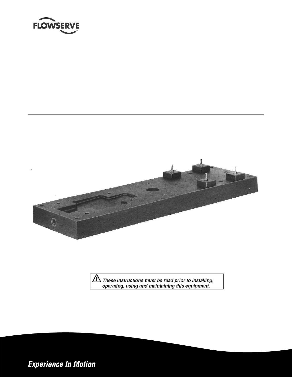
Polybase baseplates
Non-metallic, solid polymer concrete
AMSE B73.1 and ISO 3661 dimensions
PCN=71569284 – 12-10 Original instructions
Installation
Operation
Maintenance
Page 2

Polybase Baseplate USER INSTRUCTIONS ENGLISH 71569284 USER – 12-10
CONTENTS
1 INTRODUCTION AND SAFETY.......................3
1.1 General.........................................................3
1.2 CE marking and approvals ...........................3
1.3 Disclaimer.....................................................3
1.4 Copyright ......................................................3
1.5 Duty conditions .............................................3
1.6 Safety............................................................4
1.7 Nameplate and safety labels........................6
2 TRANSPORT AND STORAGE.........................6
2.1 Consignment receipt and unpacking............6
2.2 Handling........................................................6
2.3 Lifting ............................................................6
2.4 Storage .........................................................8
2.5 Recycling and end of product life .................8
3 DESCRIPTION .................................................8
3.1 Configurations...............................................8
3.2 Nomenclature ...............................................9
3.3 Design of major parts....................................9
3.4 Performance and operation limits.................9
4 INSTALLATION ..............................................11
4.1 Location ......................................................11
4.2 Part Assemblies..........................................11
4.3 Foundation..................................................11
4.4 Grouting......................................................15
5 COMMISSIONING, STARTUP, OPERATION
AND SHUTDOWN...................................................16
6 MAINTENANCE..............................................16
6.1 Maintenance schedule................................16
6.2 Spare parts..................................................16
6.3 Recommended spares and consumable
items ...........................................................17
6.4 Tools required.............................................17
6.5 Field thread insert installation procedure....17
6.6 Field installed thread insert testing
(Optional)....................................................18
6.7 Recommended fastener mounting
torques........................................................19
7 FAULTS: CAUSES AND REMEDIES............. 20
8 PARTS LIST AND DRAWINGS...................... 21
9 CERTIFICATION ............................................22
10 OTHER RELEVANT DOCUMENTATION AND
MANUALS ...............................................................22
10.1 Supplementary user instructions............22
10.2 Change Notes ........................................22
10.3 Additional sources of information...........22
Page 2 of 24 flowserve.com
Page 3

Polybase Baseplate INSTRUCTIONS ENGLISH 71569284 – 12-10
1 INTRODUCTION AND SAFETY
1.1 General
These instructions must always be kept
close to the product's operating location or
directly with the product.
Flowserve products are designed, developed and
manufactured with state-of-the-art technologies in
modern facilities. The unit is produced with great
care and commitment to continuous quality control,
utilizing sophisticated quality techniques, and safety
requirements.
Flowserve is committed to continuous quality
improvement and being at service for any further
information about the product in its installation and
operation or about its support products, repair and
diagnostic services.
These instructions are intended to facilitate
familiarization with the product and its permitted use.
Operating the product in compliance with these
instructions is important to help ensure reliability in
service and avoid risks. The instructions may not
take into account local regulations; ensure such
regulations are observed by all, including those
installing the product. Always coordinate repair
activity with operations personnel, and follow all plant
safety requirements and applicable safety and health
laws and regulations.
These instructions must be read prior to
installing, operating, using and maintaining the
equipment in any region worldwide. The
equipment must not be put into service until all
the conditions relating to safety noted in the
instructions, have been met. Failure to follow and
apply the present user instructions is considered
to be misuse. Personal injury, product damage,
delay or failure caused by misuse are not covered
by the Flowserve warranty.
1.2 CE marking and approvals
It is a legal requirement that machinery and equipment
put into service within certain regions of the world shall
conform with the applicable CE Marking Directives
covering Machinery and, where applicable, Low Voltage
Equipment, Electromagnetic Compatibility (EMC),
Pressure Equipment Directive (PED) and Equipment for
Potentially Explosive Atmospheres (ATEX).
Where applicable the Directives and any additional
Approvals cover important safety aspects relating to
machinery and equipment and the satisfactory provision
of technical documents and safety instructions. Where
applicable this document incorporates information
relevant to these Directives and Approvals.
To confirm the Approvals applying and if the product is
CE marked, check the serial number plate markings
and the Certification. (See section 9, Certification.)
1.3 Disclaimer
Information in these User Instructions is believed
to be complete and reliable. However, in spite of
all of the efforts of Flowserve Corporation to
provide comprehensive instructions, good
engineering and safety practice should always be
used.
Flowserve manufactures products to exacting
International Quality Management System Standards as
certified and audited by external Quality Assurance
organizations. Genuine parts and accessories have
been designed, tested and incorporated into the
products to help ensure their continued product quality
and performance in use. As Flowserve cannot test
parts and accessories sourced from other vendors the
incorrect incorporation of such parts and accessories
may adversely affect the performance and safety
features of the products. The failure to properly select,
install or use authorized Flowserve parts and
accessories is considered to be misuse. Damage or
failure caused by misuse is not covered by the
Flowserve warranty. In addition, any modification of
Flowserve products or removal of original components
may impair the safety of these products in their use.
1.4 Copyright
All rights reserved. No part of these instructions may
be reproduced, stored in a retrieval system or
transmitted in any form or by any means without prior
permission of Flowserve.
1.5 Duty conditions
This product has been selected to meet the
specifications of your purchaser order. The
acknowledgement of these conditions has been sent
separately to the Purchaser. A copy should be kept
with these instructions.
The product must not be operated beyond
the parameters specified for the application. If
there is any doubt as to the suitability of the
product for the application intended, contact
Flowserve for advice, quoting the serial number.
If the conditions of service on your purchase order
are going to be changed (for example liquid pumped,
temperature or duty) it is requested that the user
seeks the written agreement of Flowserve before
start up.
Page 3 of 24 flowserve.com
Page 4

Polybase Baseplate INSTRUCTIONS ENGLISH 71569284 – 12-10
1.6 Safety
1.6.1 Summary of safety markings
These User Instructions contain specific safety
markings where non-observance of an instruction would
cause hazards. The specific safety markings are:
This symbol indicates electrical safety
instructions where non-compliance will involve a high
risk to personal safety or the loss of life.
This symbol indicates safety instructions where
non-compliance would affect personal safety and
could result in loss of life.
This symbol indicates “hazardous and toxic fluid”
safety instructions where non-compliance would affect
personal safety and could result in loss of life.
This symbol indicates safety
instructions where non-compliance will involve some
risk to safe operation and personal safety and would
damage the equipment or property.
This symbol indicates explosive atmosphere
zone marking according to ATEX. It is used in safety
instructions where non-compliance in the hazardous
area would cause the risk of an explosion.
This symbol is used in safety instructions to
remind not to rub non-metallic surfaces with a dry
cloth; ensure the cloth is damp. It is used in safety
instructions where non-compliance in the hazardous
area would cause the risk of an explosion.
This sign is not a safety symbol but indicates
an important instruction in the assembly process.
1.6.2 Personnel qualification and training
All personnel involved in the operation, installation,
inspection and maintenance of the unit must be
qualified to carry out the work involved. If the
personnel in question do not already possess the
necessary knowledge and skill, appropriate training
and instruction must be provided. If required the
operator may commission the manufacturer/supplier
to provide applicable training.
Always coordinate repair activity with operations and
health and safety personnel, and follow all plant
safety requirements and applicable safety and health
laws and regulations.
1.6.3 Safety action
This is a summary of conditions and actions to
prevent injury to personnel and damage to the
environment and to equipment. For products
used in potentially explosive atmospheres
section 1.6.4 also applies.
NEVER DO MAINTENANCE WORK
WHEN THE UNIT IS CONNECTED TO POWER
(Lock Out)
HANDLING COMPONENTS
Many precision parts have sharp corners and the
wearing of appropriate safety gloves and equipment
is required when handling these components. To lift
heavy pieces above 25 kg (55 lb) use a crane
appropriate for the mass and in accordance with
current local regulations.
HOT (and cold) PARTS
If hot or freezing components or auxiliary heating
equipment can present a danger to operators and
persons entering the immediate area, action must be
taken to avoid accidental contact (such as shielding).
If complete protection is not possible, the machine
access must be limited to maintenance staff only with
clear visual warnings and indicators to those entering
the immediate area. Note: bearing housings must not
be insulated and drive motors and bearings may be
hot.
If the temperature is greater than 80°C (175 °F) or
below -5 °C (23 °F) in a restricted zone, or
exceeds local regulations, action as above shall
be taken.
PREVENT EXCESSIVE EXTERNAL
PIPE LOAD
Do not use pump as a support for piping. Do not
mount expansion joints, unless allowed by Flowserve
in writing, so that their force, due to internal pressure,
acts on the pump flange.
HAZARDOUS LIQUIDS
When the pump is handling hazardous liquids care
must be taken to avoid exposure to the liquid by
appropriate pump placement, limiting personnel
access and by operator training. If the liquid is
flammable and/or explosive, strict safety procedures
must be applied.
Page 4 of 24 flowserve.com
Page 5
Polybase Baseplate INSTRUCTIONS ENGLISH 71569284 – 12-10
1.6.4 Products used in potentially explosive
atmospheres
Measures are required to:
• Avoid excess temperature
• Prevent build up of explosive mixtures
• Prevent the generation of sparks
• Prevent leakages
• Maintain the pump to avoid hazard
The following instructions for pumps and pump units
when installed in potentially explosive atmospheres
must be followed to help ensure explosion protection.
For ATEX, both electrical and non-electrical equipment
must meet the requirements of European Directive
94/9/EC. Always observe the regional legal Ex
requirements eg Ex electrical items outside the EU may
be required certified to other than ATEX eg IECEx,
UL/CSA.
1.6.4.1 Scope of compliance
Use equipment only in the zone for which it is
appropriate. Always check that the driver, drive
coupling assembly, seal and pump equipment are
suitably rated and/or certified for the classification of the
specific atmosphere in which they are to be installed.
Where Flowserve has supplied only the bare shaft
pump, the Ex rating applies only to the pump. The party
responsible for assembling the pump set shall select the
coupling, driver and any additional equipment, with the
necessary CE Certificate/ Declaration of Conformity
establishing it is suitable for the area in which it is to be
installed. That party are also responsible for CE
Marking the complete machine.
The output from a variable frequency drive (VFD) can
cause additional heating effects in the motor and so,
for pumps sets with a VFD, the ATEX Certification for
the motor must state that it is covers the situation
where electrical supply is from the VFD. This
particular requirement still applies even if the VFD is
in a safe area.
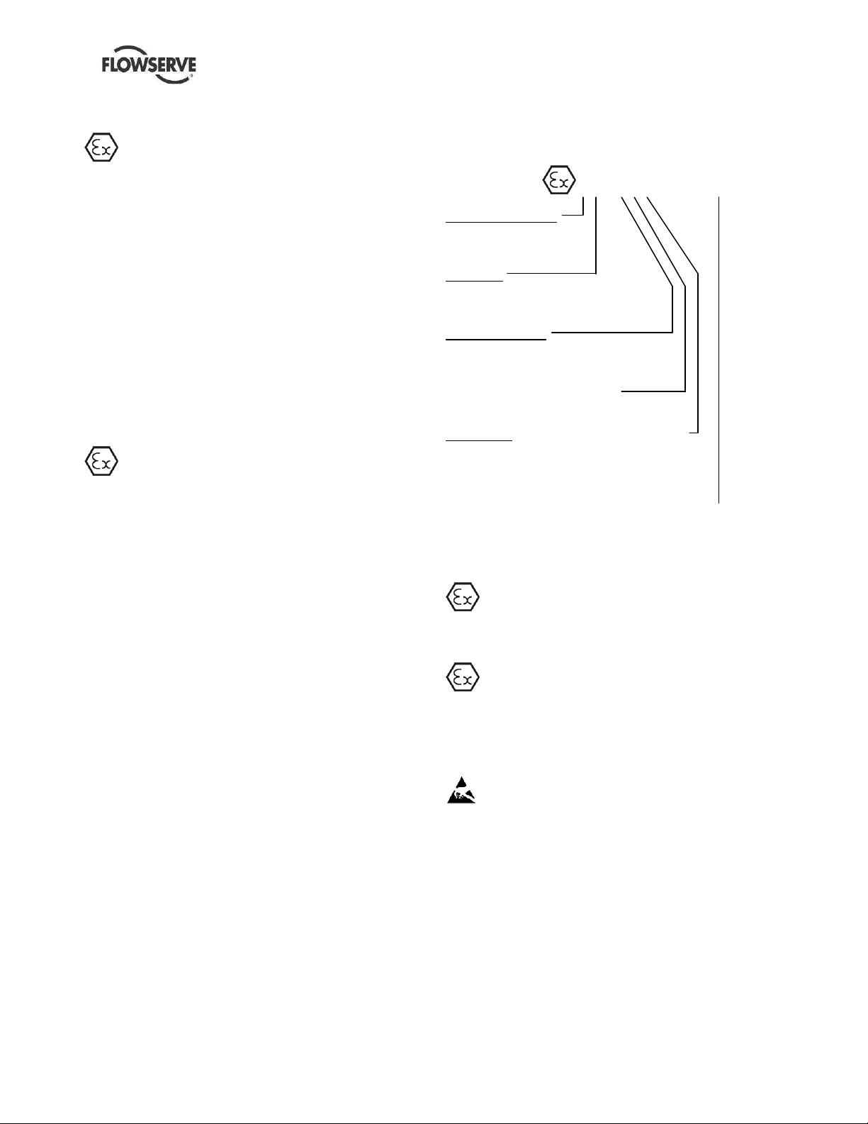
1.6.4.2 Marking
An example of ATEX equipment marking is shown
below. The actual classification of the pump will be
engraved on the nameplate.
II 2 GD c IIC T135 ºC (T4)
Equipment Group
I = Mining
II = Non-mining
Category
2 or M2 = high level protection
3 = normal level of protection
Gas and/or dust
G = Gas
D = Dust
c = Constructional safety
(in accordance with EN13463-5)
Gas Group
IIA – Propane (typical)
IIB – Ethylene (typical)
IIC – Hydrogen (typical)
Maximum surface temperature (Temperature Class)
(see section 1.6.4.3.)
1.6.4.3 Avoiding excessive surface
temperatures
ENSURE THE EQUIPMENT TEMPERATURE
CLASS IS SUITABLE FOR THE HAZARD ZONE
1.6.4.4 Preventing sparks
To prevent a potential hazard from mechanical
contact, the coupling guard must be non-sparking.
To avoid the potential hazard from random induced
current generating a spark, the earth contact on the
baseplate must be used.
Avoid electrostatic charge: do not rub non-metallic
surfaces with a dry cloth; ensure cloth is damp.
The coupling must be selected to comply with 94/9/EC
and correct alignment must be maintained.
Additional requirement for metallic pumps on
non-metallic baseplates
When metallic components are fitted on a nonmetallic baseplate they must be individually earthed.
Page 5 of 24 flowserve.com
Page 6

Polybase Baseplate INSTRUCTIONS ENGLISH 71569284 – 12-10
1.6.4.5 Maintenance to avoid the hazard
CORRECT MAINTENANCE IS REQUIRED TO
AVOID POTENTIAL HAZARDS WHICH GIVE A
RISK OF EXPLOSION
The responsibility for compliance with maintenance
instructions is with the plant operator.
To avoid potential explosion hazards during
maintenance, the tools, cleaning and painting
materials used must not give rise to sparking or
adversely affect the ambient conditions. Where there
is a risk from such tools or materials, maintenance
must be conducted in a safe area.
It is recommended that a maintenance plan and
schedule is adopted. (See section 6, Maintenance.)
1.7 Nameplate and safety labels
1.7.1 Safety labels
2 TRANSPORT AND STORAGE
2.1 Consignment receipt and unpacking
Immediately after receipt of the equipment it must be
checked against the delivery/shipping documents for
its completeness and that there has been no damage
in transportation. Any shortage and/or damage must
be reported immediately to Flowserve Pump Division
and must be received in within ten days of receipt of
the equipment. Later claims cannot be accepted.
Check all crates, boxes or wrappings for any
accessories or spare parts that may be packed
separately from the equipment or attached to side
walls of the box or equipment. After unpacking,
protection will be the responsibility of the user.
Each product has a unique serial number. Check
that this number corresponds with your order. Use
this number in correspondence as well as when
ordering spare parts or further accessories.
2.2 Handling
Boxes, crates, pallets or cartons may be unloaded
using fork-lift vehicles or slings depending on their
size and construction.
2.3 Lifting
Fully trained personnel must carry out lifting in
accordance with local regulations. The Polybase
baseplate dimensions and weights are shown in
Section 8 PARTS LIST AND DRAWINGS.
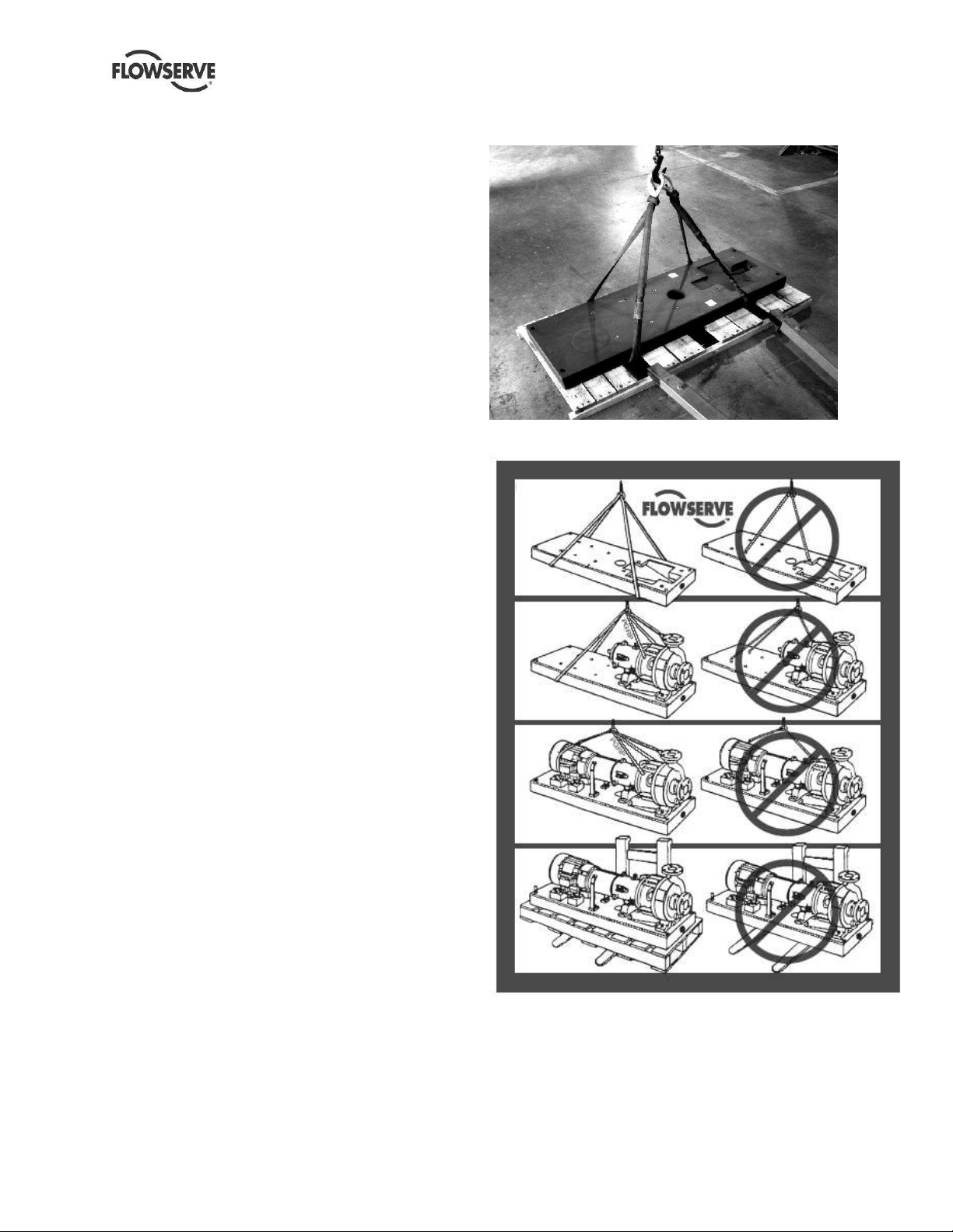
.Do not install eye bolts in the Polybase
thread inserts for the purpose of lifting the base. This
practice imposes lateral loads on the inserts which
they were not designed to withstand. Also, do not use
hooks in the baseplate anchor bolt holes.
Pumps and motors often have integral
lifting lugs or eye bolts. These are intended for use in
only lifting the individual piece of equipment.
Do not use eye bolts or cast-in lifting
lugs to lift pump, motor and baseplate assemblies.
Polybase units should be transported
via fork truck to the area of their intended installation
on the wooden pallets on which they were shipped.
Never transport a Polybase over long distances or
over rough terrain while it is suspended from slings.
Care must be taken to lift components
or assemblies above the center of gravity to prevent
the unit from flipping.
Page 6 of 24 flowserve.com
Page 7
Polybase Baseplate INSTRUCTIONS ENGLISH 71569284 – 12-10
2.3.1 Lifting Polybase baseplates with no
mounted equipment
a) Remove the fasteners that hold the Polybase to
the wooden pallet.
b) Slip two slings under the baseplate between
pallet cross-members as shown in Figure 2.1.
Slings should be positioned approximately onequarter to one-third the baseplate length from
each end.
c) Lift the Polybase a few inches off the pallet and
verify that it hangs reasonably level and that the
slings are not prone to slipping out of position.
d) If this slinging appears to be unstable, set the
baseplate back on the pallet and reposition the
slings. After satisfactory slinging has been
achieved, the baseplate may be hoisted onto its
foundation.
2.3.2 Lifting the Polybase baseplate with pump
and motor installed
a) Remove the fasteners that hold the Polybase to
the wooden pallet.
b) Install slings around the pump discharge nozzle
(except for PGRP pumps where the slings must
go around and through the adapter) and around
the outboard end of the motor frame using
choker hitches pulled tight. The motor sling
should be positioned so the weight is not carried
through the fan housing. Make sure the
completion of the choker hitch on the discharge
nozzle (or adapter arms) is toward the coupling
end of the pump shaft as shown in Figure 2.2.
2.3.3 Lifting the Polybase baseplate with only
the pump installed
a) Remove the fasteners that hold the Polybase to
the wooden pallet.
b) Install a sling around the pump discharge nozzle
using a choker hitch pulled tight (except for
PGRP pumps where the slings must go around
and through the adapter).
c) Install a second sling around the motor end of
the Polybase using a basket hitch (see Figure
2.2). Make sure the completion of the choker
hitch on the discharge nozzle is toward the
coupling end of the pump shaft. Refer to section
4.0 INSTALLATION for setting the base on the
foundation.
d)
Figure 2.1
Figure 2.2
Page 7 of 24 flowserve.com
Page 8

Polybase Baseplate INSTRUCTIONS ENGLISH 71569284 – 12-10
2.4 Storage
This section addresses the storage procedures for
the Polybase baseplate only. When storing a
Polybase baseplate with mounted pump assemblies,
it is extremely important that the proper storage
procedures for the pump be observed as well. Refer
to the User Instruction for the particular pump that is
mounted on your baseplate. Flowserve's normal
packaging is designed to protect the Polybase
baseplate during shipment and handling from the
time it is assembled at the factory to installation at the
end user's jobsite. If the Polybase baseplate is to be
stored for a period of time prior to installation, it is
recommended that the following procedures be
followed:
a) Leave the baseplate bolted to its wooden
shipping pallet.
b) Place the pallet on a solid, dry, level surface in a
location where the base cannot be struck by
passing fork trucks, falling objects, etc. Make
sure that the pallet does not rock.
c) Do not stack heavy objects on top of the
baseplate.
d) If the Polybase will be installed in an indoor
location, but is to be stored in an outdoor
location, cover the base completely with a
tarpaulin or dark plastic sheeting to prevent UV
degradation of the surface. NOTE: UV
degradation (bleaching) of the polymer concrete
is the normal result of exposure to sunlight. This
phenomenon is purely a visual change in the
color of the material which in no way
compromises the performance or corrosion
resistance characteristics of the Polybase
baseplate.
e) Multiple Polybase baseplates without installed
equipment may be stacked, provided the bases
are level and the stacking is done in a manner
which uniformly distributes the weight of the
upper base to the top surface of the base on
which it rests. A minimum of two pallet crossmembers should contact the entire width of the
lower base. Cross members must not rest on
fasteners or on the corners of the lower base.
Do not attempt to stand a Polybase
baseplate on end to make more efficient use of
storage space. Neither the base nor the fasteners
that hold the base to its wooden pallet have been
designed for vertical storage. Severe personal
injury or death, as well as irreparable damage to
Polybase baseplate, may result if it tips over.
f) After unpacking, protection will be the
responsibility of the user.
2.5 Recycling and end of product life
At the end of the service life of the product or its
parts, the relevant materials and parts should be
recycled or disposed of using an environmentally
acceptable method and in accordance with local
regulations. If the product contains substances that
are harmful to the environment, these should be
removed and disposed of in accordance with current
local regulations. This also includes the liquids
and/or gases that may be used in the "seal system"
or other utilities.
Make sure that hazardous substances are
disposed of safely and that the correct personal
protective equipment is used. The safety
specifications must be in accordance with the current
local regulations at all times.
3 DESCRIPTION
3.1 Configurations
The Flowserve Polybase baseplate is a solid,
polymer concrete baseplate that is manufactured in
versions that conform to both ASME B73.1 and ISO
3661.
ASME Polybase units are manufactured with integral
drain basin and grout hole. Integral leveling screw
thread inserts facilitate proper installation. Twelve
sizes are available ranging from 139 through 398.
ISO Polybase units are manufactured with integral
drain basin, and are available in sizes ISO 3, 4, 5, 6,
7 and 8.
Metallic thread inserts are provided in the mounting
surfaces for particular combinations of pump and
motors. Multiple motor insert patterns are also
available, and custom insert configurations can be
produced per customer specifications. The standard
thread insert material is 304SS (18.10 CrNi stainless
steel), with higher alloys available upon request.
Three different epoxy vinyl ester resin materials are
available to support the use of Polybase baseplates
in most chemical applications (see 3.3.2).
Additional available options include stilt mounting and
flush plan mounting.
Page 8 of 24 flowserve.com
Page 9

Polybase Baseplate INSTRUCTIONS ENGLISH 71569284 – 12-10
The Polybase baseplate utilizes as standard the
unique Polybloc mounting system. This system is
comprised of corrosion resistant polymer concrete
mounting blocks having surface flatness and
parallelism equivalent to machined steel blocks.
Motor mounting Polyblocs incorporate the unique
Bloc-loc™ counterbore/jam nut feature for positive
attachment to the baseplate (Figure 3.1).
The optional 8-point™ motor adjusters and the Blocloc™ features are joined to provide axial and
transverse motor adjustment (Figure 3.1).
Figure 3.1
Counterbore type Mounting Polyblocs are also totally
suitable if order requirements do not require that
motor Polyblocs must be independently locked to the
baseplate. In this case the polymeric block are fitted
with the counterbore side of the block facing the
surface of the baseplate.
3.2 Nomenclature
Individual baseplate sizes in the Polybase baseplate
product line are identified by the ASME B73.1 pump
group size they support and the length of the
baseplate. For example:
139 = Group 1 pumps; 39 inches long.
264 = Group 2 pumps; 64 inches long.
398 = Group 3 pumps; 98 inches long.
The length of the baseplate determines the motor
frame size that can be fitted. The longer baseplates
allow larger motors to be fitted.
3.3 Design of major parts
3.3.1 Baseplate materials of construction
The body of a Polybase baseplate is composed of an
epoxy vinyl ester resin with integral silica aggregate.
The threaded inserts are made of 304SS. The
inserts are retained in the Polybase baseplate by a
two-part industrial epoxy (Master Bond EP21LV or
equivalent).
3.3.2 Resin options
The standard epoxy resin is Derakane 411-50 (black
or gray in color). Novolac GT4500 resin is optional
for severe sulfuric acid services (red in color).
Novolac GT4000 resin is optional for chlorinated
solvent services (blue in color).
3.4 Performance and operation limits
This product has been selected to meet the
specification of your purchase order (see section 1.5).
The following data are included as additional
information to help with your installation. If required,
a definitive statement for your application can be
obtained from Flowserve.
3.4.1 Temperature ratings
The maximum equipment temperature that can be
tolerated by the various Polybase resins is listed
below:
Black bases (Derakane) = 149 °C (300 °F)
Red bases (GT 4500) = 82 °C (180 °F)
Blue bases (GT4000) = 104 °C (220 °F)
The minimum acceptable temperature for the
Polybase resins is -45 °C (-50 °F).
Page 9 of 24 flowserve.com
Page 10

Polybase Baseplate INSTRUCTIONS ENGLISH 71569284 – 12-10
3.4.2 Polybase corrosion guide (abridged)
Table 3-1 Derakane resin (black)
Chemical
Acetic acid <75%
Acetic, glacial
Amines
Aromatic solvents
Benzene
Bleach
Bromine (dry)
Bromine (wet)
Calcium chloride
Chlorinated solvents
Chlorobenzene
Chlorine dioxide
<15%
Chromic acid <20%
Ferric chloride
Fluosilic acid <30%
Gasoline
Hydrobromic acid
<50%
Hydrochloric acid
=<20%
Hydrochloric >20%
Hydrofluoric acid
<20%
Methylene chloride
Nitric acid =<30%
Nitric acid >30%
Oil, mineral
Petroleum oil
Phosphoric acid
Seawater
Sodium chlorate
Sodium chloride
Sodium hydroxide
=<50%
Sodium hydroxide
>50%
Sulfuric acid <75%
75% to 93%
93% to 98+%
21 °C
(70 °F)
60 °C
(140 °F)
93 °C
(200 °F)
R R S
S NR NR
R S NR
S NR NR
NR NR NR
R R NR
R NR NR
R NR NR
R R S
NR NR NR
NR NR NR
R R S
R NR NR
R R R
R NR NR
R R NR
R R NR
R R S
R S NR
R S NR
NR NR NR
R S NR
NR NR NR
R R R
R R R
R R R
R R R
R R R
R R R
R R S
NR NR NR
R S S
NR NR NR
NR NR NR
Table 3-2 Novolac GT4000 resin (blue)
Chemical
Acetic acid <75%
Acetic, glacial
Benzene
Bleach =<18%
Chromic acid <20%
Hydrochloric acid
=<20%
Hydrochloric >20%
Hydrofluoric acid
<20%
Methylene chloride
Nitric acid to 69%
Sodium hydroxide
=<50%
Sodium hydroxide
>50%
Sulfuric acid <75%
75% to 93%
93% to 98+%
21 °C
(70 °F)
R R R
R R R
R R R
R R R
R R R
R R R
R R R
R S NR
S NR NR
R R R
R R R
NR NR NR
R R R
S NR NR
S NR NR
Table 3-3 Novolac GT4500 resin (red)
Chemical
Bleach to 12%
Chromic acid <20%
Gasoline
Hydrochloric acid
=<20%
Hydrochloric >20%
Hydrofluoric acid
<20%
Methylene chloride
Nitric acid to 50%
Phosphoric acid to
85%
Sodium hydroxide
=<50%
Sodium hydroxide
>50%
Sulfuric acid <75%
75% to 93%
93% to 98+%
21 °C
(70 °F)
R R
R R
R R
R R
R R
R S
NR NR
R R
R R
R R
NR NR
R R
R R
R R
R = Recommended.
S= Satisfactory for occasional contact at some
concentrations – consult Flowserve Materials
Engineering Department.
NR = Not recommended.
60 °C
(140 °F)
60 °C
(140 °F)
93 °C
(200 °F)
Page 10 of 24 flowserve.com
Page 11

Polybase Baseplate INSTRUCTIONS ENGLISH 71569284 – 12-10
4 INSTALLATION
Equipment operated in hazardous locations
must comply with the relevant explosion protection
regulations. See section 1.6.4, Products used in
potentially explosive atmospheres.
4.1 Location
The baseplate should be located to allow room for
access, ventilation, maintenance, and inspection with
ample headroom for lifting and should be as close as
practicable to the supply of liquid to be pumped.
Refer to the general arrangement drawing for the
pump set.
4.2 Part Assemblies
The supply of motors and pumps are optional. As a
result, it is the responsibility of the installer to ensure
that the motor is assembled to the pump and aligned
as detailed in section 4.5 and 4.8.
4.3 Foundation
4.3.1 Protection of openings and threads
When the baseplate is shipped, all threads and all
openings are covered. This protection/covering
should not be removed until installation. If, for any
reason, the baseplate is removed from service, this
protection should be reinstalled.
4.3.2 Rigid baseplates - overview
The function of a baseplate is to provide a rigid
foundation under a pump and its driver that maintains
alignment between the two. Baseplates may be
generally classified into two types:
• Foundation-mounted, grouted design (Figure 4-1)
• Stilt mounted, or free-standing (Figure 4-2)
Figure 4.1
Figure 4.2
Baseplates intended for grouted installation are
designed to use the grout as a stiffening member.
Stilt mounted baseplates, on the other hand, are
designed to provide their own rigidity. Therefore, the
designs of the two baseplates are usually different.
The Polybase baseplate is solid and has a thick
cross-section so it can be both grouted in place and
stilt mounted.
Regardless of the type of baseplate used, it must
provide certain functions that ensure a reliable
installation. Three of these requirements are:
• The baseplate must provide sufficient rigidity to
assure the assembly can be transported and
installed, given reasonable care in handling,
without damage. It must also be rigid enough
when properly installed to resist operating loads.
• The baseplate must provide a reasonably flat
mounting surface for the pump and driver.
Uneven surfaces will result in a soft-foot condition
that may make alignment difficult or impossible.
Flowserve’s experience indicates that a baseplate
that has a top surface flatness of 1.25 mm / meter
(0.015 inch / foot) across the diagonal corners of
the baseplate provides such a mounting surface.
Therefore, this is the tolerance to which we supply
our standard baseplate. Some users may desire
an even flatter surface, which can facilitate
installation and alignment. Flowserve will supply
flatter baseplates upon request at extra cost. For
example, mounting surface flatness of 0.42 mm/m
(0.005 in./ft) is offered on the Flowserve Polybase
baseplate.
• The baseplate must be designed to allow the user
to final field align the pump and driver to within
their own particular standards and to compensate
for any pump or driver movement that occurred
during handling. Normal industry practice is to
achieve final alignment by moving the motor to
match the pump. If a pump and motor assembly
is provided with the baseplate, Flowserve’s
Page 11 of 24 flowserve.com
Page 12
Polybase Baseplate INSTRUCTIONS ENGLISH 71569284 – 12-10
practice is to confirm in our shop that the pump
assembly can be accurately aligned. Before
shipment, the factory verifies that there is enough
horizontal movement capability at the motor to
obtain a “perfect” final alignment when the installer
puts the baseplate assembly into its original, top
leveled, unstressed condition.
4.3.3 Stilt mounted Polybase baseplates
Flowserve offers a stilt mounted option for Polybase
baseplates (See Figure 4-5). The baseplate is set on
a flat surface with no tie down bolts or other means of
anchoring it to the floor.
General instructions for assembling these baseplates
are given below. For dimensional information, please
refer to the appropriate Flowserve “Sales Print.”
Note: The following assembly procedure should be
carried out as closely to the final installation location
as possible. DO NOT remove the Polybase from its
shipping pallet until it is in the area of the installation
and you are ready to assemble the stilts.
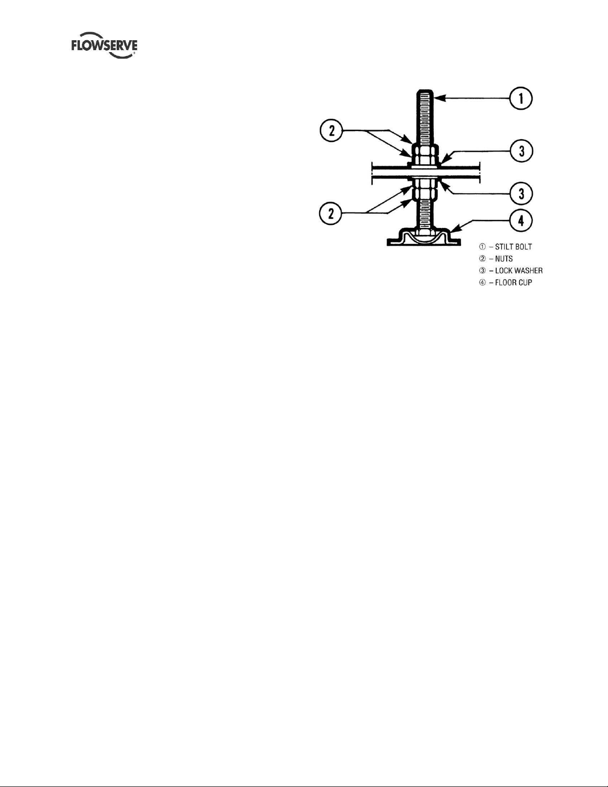
4.3.3.1 Stilt mounted baseplate assembly
instructions for 264 and shorter
Polybase baseplates (Refer to Figures 43 and 4-5)
a) Raise or block up baseplate/pump above the
floor to allow for the assembly of the stilts.
b) Bolt the cross bars onto the underside of the
Polybase baseplate.
c) Predetermine or measure the approximate
desired height for the baseplate above the floor.
d) Set the bottom nuts (item 2) above the stilt bolt
head (item 1) to the desired height.
e) Assemble lock washer (item 3) down over the stilt
bolt.
f) Assemble the stilt bolt up through hole in the
cross bar and hold in place.
g) Assemble the lock washer (item 3) and nut (item
2) on the stilt bolt. Tighten the nut down on the
lock washer.
h) After all four stilts have been assembled, position
the baseplate in place, over the floor cups (item
4) under each stilt location, and lower the
baseplate to the floor.
i) Level and make final height adjustments to the
suction and discharge pipe by first loosening the
top nuts and turning the bottom nuts to raise or
lower the baseplate.
j) Tighten the top and bottom nuts at the lock
washer (item 3) first then tighten the other nuts.
k) It should be noted that the connecting pipelines
must be individually supported, and that the stilt
mounted baseplate is not intended to support
total static pipe load.
Figure 4.3
Page 12 of 24 flowserve.com
Page 13
Polybase Baseplate INSTRUCTIONS ENGLISH 71569284 – 12-10
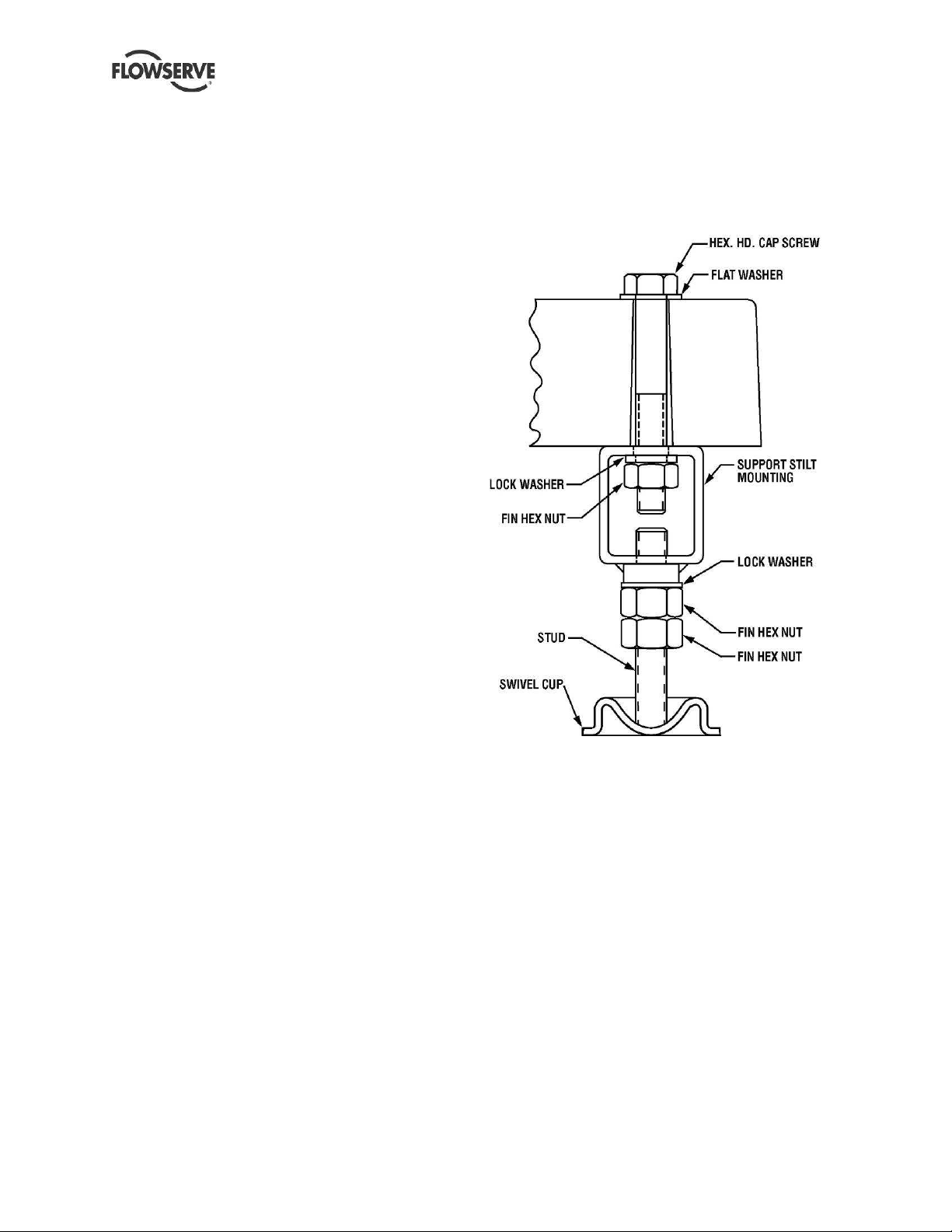
4.3.3.2 Stilt mounted baseplate assembly
instructions for 268 and longer Polybase
baseplates (Refer to Figures 4-4 and 4-5)
a) Determine or measure the approximate desired
height for the baseplate above the floor.
b) Sling and hoist the baseplate/pump assembly off
its shipping pallet in accordance with the
procedures shown in Section 2.3.
c) Bolt the stilt beams to the underside of the
Polybase using the fasteners provided as shown
in Figure 4.4. Torque the 7/8” bolts to 217Nm
(160 lbf*ft).
d) Thread two hex nuts onto each stud. Install one
internal-tooth lockwasher over the FLAT ends of
each stud. Thread the flat ends of the studs into
the weld nuts on the undersides of the
longitudinal support beams until the low point of
each SPHERICAL end is at the desired distance
from the bottom surface of the Polybase. Do not
tighten the nuts at this point.
e) After all four stilts have been assembled, position
the Polybase in place over the floor cups under
each stilt location, and GENTLY lower the
assembly to the floor.
f) Using two wrenches, lock the two hex nuts on
each stud together. Turn the studs by means of
these locked nuts to raise or lower the assembly.
When the desired leveling is achieved, unlock the
pairs of nuts and thread the upper ones (with
lockwashers on top) up until they make contact
with the weld nuts on the beams. Tighten
securely. Thread the lower nuts up and tighten to
lock the assembly in place.
g) Recheck levels and adjust if necessary.
h) It should be noted that the connecting pipe lines
must be individually supported, and that the stilt
mounted Polybase is not intended to support total
static pipe load.
4.3.3.3 Stilt mounted baseplates - motor
alignment
The procedure for motor alignment on stilt mounted
baseplates is similar to grouted baseplates. The
difference is primarily in the way the baseplate is
leveled.
a) Level the baseplate by using the stilt adjusters.
(Shims are not needed as with grouted
baseplates.) After the base is level, it is locked in
place by locking the stilt adjusters.
b) Next the initial pump alignment must be checked.
The vertical height adjustment provided by the
stilts allows the possibility of slightly twisting the
baseplate. If there has been no transit damage
or twisting of the baseplate during stilt height
adjustment, the pump and driver should be within
0.38 mm (0.015 in.) parallel, and 0.0025 mm/mm
(0.0025 in./in.) angular alignment. If this is not
the case, check to see if the driver mounting
fasteners are centered in the driver feet holes.
Figure 4.4
c) If the fasteners are not centered there was likely
shipping damage. Re-center the fasteners and
perform a preliminary alignment to the above
tolerances by shimming under the motor for
vertical alignment, and by moving the pump for
horizontal alignment.
d) If the fasteners are centered, then the baseplate
may be twisted. Slightly adjust (one turn of the
adjusting nut) the stilts at the driver end of the
baseplate and check for alignment to the above
tolerances. Repeat as necessary while
maintaining a level condition as measured from
the pump discharge flange. Lock the stilt
adjusters.
The remaining steps are the same as for new grouted
baseplates.
Page 13 of 24 flowserve.com
Page 14

Figure 4.5
Polybase Baseplate USER INSTRUCTIONS ENGLISH 71569284 USER – 12-10
Page 14 of 24 flowserve.com
Page 15

Polybase Baseplate INSTRUCTIONS ENGLISH 71569284 – 12-10
4.4 Grouting
a) The pump foundation should be located as close
to the source of the fluid to be pumped as
practical. There should be adequate space for
workers to install, operate, and maintain the
pump. The foundation should be sufficient to
absorb any vibration and should provide a rigid
support for the pump and motor. Recommended
mass of a concrete foundation should be three
times that of the pump, motor and base. Refer to
Figure 4-6 for a cross-section of the
recommended foundation and baseplate
arrangement. Note that foundation bolts are
imbedded in the concrete inside a sleeve to allow
some movement of the bolt.
Figure 4.6
b) Gently set the Polybase baseplate
down onto the foundation. Do not subject a
Polybase baseplate to heavy shock loading.
c) Level the pump baseplate assembly. The proper
surfaces to reference when leveling the pump
baseplate assembly are the pump suction and
discharge flanges.
DO NOT stress the baseplate.
DO NOT bolt the suction or discharge
flanges of the pump to the piping until the
baseplate grouting has been completed If
equipped, use leveling jackscrews to level the
baseplate. If jackscrews are not provided, shims
and wedges should be used. Check for
levelness in both the longitudinal and lateral
directions. Shims should be placed at all base
anchor bolt locations, and in the middle edge of
the base if the base is more than 1.5 m (5 ft)
long.
DO NOT RELY ON THE BOTTOM OF
THE POLYBASE BASEPLATE TO BE FLAT.
This is an as-molded surface which is not as flat
as the mounting (top) surface.
d) After leveling the baseplate, install flat washers
and nuts on the anchor bolts.
ENSURE THE NUTS HAVE A
SNUG FIT, BUT DO NOT TORQUE THEM AT
THIS POINT.
If shims are used, make sure to shim the
baseplate near each anchor bolt and snug the
nut firmly with a wrench. Failure to do this may
result in a twist of the baseplate, which could
make it impossible to obtain final alignment.
Check the level of the baseplate to ensure that it
was maintained, else adjust the jackscrews or
shims as needed until the baseplate is level
e) Check initial alignment. If the pump and motor
were removed from the baseplate, install them so
that prior to grouting it can be verified that
alignment can be achieved. If the pump and
motor were properly reinstalled to the baseplate
or if they were not removed from the baseplate
and there has been no transit damage, and also
if the above pre-grout steps where done properly,
the pump and driver should be within 0.38 mm
(0.015 in.) FIM (Full Indicator Movement) parallel,
and 0.0025 mm/mm (0.0025 in./in.) FIM angular.
If this is not the case, first check to see if the
driver mounting fasteners are centered in the
driver feet holes. If not, re-center the driver on its
fasteners and perform a preliminary alignment to
the above tolerances by shimming under the
motor for vertical alignment, and by moving the
pump for horizontal alignment.
f) Grout the baseplate. A non-shrinking grout
should be used. Make sure that the grout fills the
area under the baseplate. After the grout has
cured, check for voids and fill them if possible.
Jackscrews, shims and wedges should be
removed from under the baseplate at this time. If
they were to be left in place, they could rust,
swell, and cause distortion in the baseplate.
g) Lubricate the anchor bolt threads and torque the
nuts using a torque wrench to values noted in
table 4-1 below.
Table 4-1
Recommended
Bolt size
M12 & ½ in. 27(20)
M20 & ¾ in. 96 (70)
M22 & 7/8 in. 150 (110)
M24 & 1 in. 220 (160)
torque Nm (lbfft)
lubricated
Page 15 of 24 flowserve.com
Page 16

Polybase Baseplate INSTRUCTIONS ENGLISH 71569284 – 12-10
h) Tighten pump and motor hold
down fasteners using a torque wrench. Apply
recommended torque given in clause 6.7,
DO NOT exceed the maximum allowable torque
values provided.
i) Run piping to the suction and discharge of the
pump. There should be no piping loads
transmitted to the pump after connection is made.
Recheck the driver and pump alignment to verify
it is still acceptable. Significant loads being
carried through the pump connections can cause
misalignment.
5 COMMISSIONING, STARTUP,
OPERATION AND SHUTDOWN
Pre start-up checks
Prior to starting the equipment mounted on a
Polybase baseplate, it is essential that the following
pump-based checks be made.
• Pump and motor properly secured to the
baseplate
• All fasteners tightened to the correct torque
• Coupling guard in place and not rubbing
• Seal support system (if used) properly secured
to the baseplate
• Inspect the baseplate for cracks
• Ensure the mounted equipment is ready to run
6 MAINTENANCE
It is the plant operator's responsibility to ensure
that all maintenance, inspection and assembly work
is carried out by authorized and qualified personnel
who have adequately familiarized themselves with
the subject matter by studying this manual in detail.
(See also section 1.6)
Any work on the machine must be performed when it
is at a standstill. It is imperative that the procedure
for shutting down the machine is followed.
On completion of work all guards and safety devices
must be re-installed and made operative again.
Oil and grease leaks may make the ground
slippery. Machine maintenance must always
begin and finish by cleaning the ground and the
exterior of the machine.
If platforms, stairs and guard rails are required for
maintenance, they must be placed for easy access to
areas where maintenance and inspection are to be
carried out. The positioning of these accessories
must not limit access or hinder the lifting of the part to
be serviced.
Place a warning sign on the starting device:
"Machine under repair: do not start".
With electric drive equipment, lock the main switch
open and withdraw any fuses. Put a warning sign on
the fuse box or main switch:
"Machine under repair: do not connect".
Never clean equipment with flammable solvents or
carbon tetrachloride. Protect yourself against toxic
fumes when using cleaning agents.
6.1 Maintenance schedule
It is recommended that a maintenance plan and
schedule be implemented to support the equipment
mounted on a Polybase baseplate. The Polybase
baseplate does not require any maintenance, but the
following should be checked during routine
maintenance of the mounted equipment:
• clean the surface of the baseplate to prevent long
term chemical attack from degrading the surface
(refer to 1.6.4.4 to prevent sparks when product
must comply with ATEX)
• check that the mounted equipment is securely
fastened to the baseplate
• inspect the surface of the baseplate for any
cracks.
6.2 Spare parts
The Polybase baseplate does not require any spare
parts unless it is damaged. If one of the threaded
inserts in the Polybase baseplate comes loose, or the
owner needs to add additional inserts to an installed
Polybase baseplate, the inserts are available from
Flowserve. A two-part industrial epoxy (Master Bond
EP21LV, Loctite E-120HP, or equivalent) is required
to bond the inserts in place. Replacement parts for
stilt mounted assemblies can also be supplied by
Flowserve.
To order spare parts
Flowserve keeps records of all products that have
been supplied. Spare parts can be ordered from your
local Flowserve Sales Engineer or from a Flowserve
Distributor or Representative. When ordering spare
parts the following information should be supplied:
1) Baseplate size
2) Motor size
3) Material of construction (color)
4) For thread repairs -- insert size and
quantity required
Page 16 of 24 flowserve.com
Page 17

Polybase Baseplate INSTRUCTIONS ENGLISH 71569284 – 12-10
5) For stilt mounts, the type and number
must be specified
If the spare Polybase baseplate is intended to
be used with equipment which is or will be installed in
a potentially explosive atmosphere, Flowserve should
be given the complete ATEX classification of the
equipment in order to check compliance.
6.3 Recommended spares and
consumable items
There are no recommended spare parts for the
Polybase baseplate. In the rare instances when a
threaded insert needs to be replaced or a Polybase
baseplate needs to be drilled and inserted for a
different size motor, the following materials and
procedure would apply.
6.4 Tools required
For drilling holes in the Polybase material, use a
masonry bit or a carbine-tipped drill bit.
6.5 Field thread insert installation
procedure
The procedure detailed below may be used either to
replace a damaged original thread insert or to install
an insert in a new location.
Thread inserts properly installed in the field
will yield performance characteristics and service life
equivalent to inserts installed at the factory. Field
installation should only be undertaken when
absolutely necessary, and then only by qualified
personnel using suitable drilling equipment. In order
to achieve a successful installation the following
procedures must be followed PRECISELY and the
drilling operation must be carried out AS
ACCURATELY AS POSSIBLE.
a) Drill out the damaged insert (or drill a new hole in
a location that has been carefully laid out) taking
care not to enlarge or elongate the hole into
which the replacement insert will be installed. It
is critical that the hole be drilled perpendicular to
the surface of the Polybase and that the hole
center line location be maintained. The
recommended method for achieving this is to use
a carbide tipped bit with a magnetic base drill
mounted on a steel plate that has been bolted to
the adjacent inserts in the baseplate (see Figure
6.1). Correct drill diameters and depths are
shown in Table 6-1.
DO NOT USE OIL OR CUTTING FLUID -
HOLES MUST BE DRILLED DRY.
Figure 6.1
b) Remove all dust and metal chips from the drilled
hole using dry, oil-free compressed air.
c) If the drilled hole has become contaminated with
oil or other foreign substance, flush thoroughly
with acetone or ethyl acetate and dry completely
with oil-free compressed air.
d) If the replacement insert has been contaminated
with oil or other foreign substance, flush
thoroughly with acetone or ethyl acetate and dry
completely with oil-free compressed air.
e) Dispense adhesive into the drilled hole (see
Figure 6.2) following the instructions provided.
Fill the hole to within approximately 12 mm (1/2
inch) of the baseplate surface.
Figure 6.2
f) After applying oil to the threads of a properly
sized socket head cap screw (or hex head bolt),
thread it into the insert. Be careful not to get any
oil on the outside surfaces of the insert.
Page 17 of 24 flowserve.com
Page 18

Polybase Baseplate INSTRUCTIONS ENGLISH 71569284 – 12-10
g) Engage the blind end of the stainless steel insert
in the hole. Tap on the cap screw head with light
hammer or soft mallet to drive the insert into the
hole (see Figure 6.3). Hold the insert straight
until it has been driven in to approximately half its
length; the insert is self-aligning once it has
passed this point.
Figure 6.3
h) Drive the insert in slowly to give
the adhesive time to flow around the grooves in
the insert. Drive the insert in to the point where
its top surface is flush with or just below the
surface of the baseplate. Excess adhesive will
squeeze out and pool around the top of the insert
as shown in Figure 6.4. Do not remove this
excess material. As the adhesive cures, some of
this excess will draw down into the space
between the insert and the wall of the hole. Do
not remove the cap screw at this time.
Figure 6.4
l) The baseplate is now ready to be put back into
service. The equipment fasteners mounting
torques are given in clause 6.7 Table 6-3.
Do not exceed the maximum
torque value given in Table 6-3in relation to
fastener mechanical properties.
Table 6-1
Drill Diameter
Thread Size mm inches
5/16-18 UNC 18 45/64 (.703)
3/8-16 UNC 18 45/64 (.703)
M6 18 45/64 (.703)
M8 18 45/64 (.703)
M10 18 45/64 (.703)
1/2-13 UNC 21 53/64 (.828)
M12 21 53/64 (.828)
5/8-11 UNC 29 1-1/8 (1.125)
3/4-10 UNC 29 1-1/8 (1.125)
M16 29 1-1/8 (1.125)
M20 29 1-1/8 (1.125)
7/8-9 UNC 32 1-1/4 (1.250)
M24 32 1-1/4 (1.250)
Depth (all) 46 1-13/16 (1.81)
6.6 Field installed thread insert
testing (Optional)
If user elects to assess the validity of his installation
or replacement of thread inserts, here are provided
the necessary bolts torques for the axial pull-out
testing of the insert sample(s).
The torque values tabulated below are
maximums that the inserts in the Polybase baseplate
can withstand without any damage. These values
may exceed the material strength of the bolts being
used to do the test. The end user must consider the
type of bolt and lubrication used (if any) before
tightening.
i) Allow the adhesive to cure undisturbed for 48
hours.
j) Following cure remove the screw. Excess
adhesive may be chipped off with a putty knife. If
desired, lightly sand the surface of the baseplate
to a flat, smooth condition.
k) OPTIONAL. It is up to the user to decide if a
sample insert axial pullout test is needed using
torque values given in clause 6.6.
Page 18 of 24 flowserve.com
Page 19

Polybase Baseplate INSTRUCTIONS ENGLISH 71569284 – 12-10
Table 6-2 Insert testing unlubricated torque limits
Test boltsize Nm (lbf•ft)
M6 16 (12)
M8 and 5/16 in. 22 (16)
M10 and 3/8 in. 45 (33)
M12 and ½ in. 105 (77)
M16 and 5/8 in. 150 (111)
M20 and ¾ in. 220 (162)
7/8 in. 275 (203)
M24 and 1 in. 410 (302)
All torques in table are for dry threads.
Note: 1.) For lubricated threads, use 75% of the values.
2.) Excessive torque can damage the Polybase
baseplate by pulling out the inserts.
3) These are maximum values valid for testing the
inserts, Fastener torquefor mounting the
equipmentis given clause 6.7.
4) As a default, the bolts used for insert testing
should be scrapped. They must not be reused if
the torque during test has attained 90% or more
of the proof test value of the bolt material or 80%
of its yield strength, whichever is the lowe
r.
6.7 Recommended fastener mounting
torques
Tighten pump and motor hold down fasteners using a
torque wrench. Apply table 6-3 recommended
torques.
DO NOT EXCEED THE HIGHEST
TORQUE VALUE.
Any fastener material used for mounting the
equipment to the Polybase must have a minimum
yield strength of 210 MPa (30 KSI) at room
temperature.
Table 6-3 Equipment fasteners mounting torques
Fastener Mechanical Property
Fastener Size
X
Strength
(1)
Max Torque
(dry)
Nm (
lbf•ft)
Y
Max Torque
Strength
Nm (
(dry)
lbf•ft)
(2)
M6 8 (6) 12 (9)
5/16 in. 8 (6) 17 (13)
M8 11 (8) 17 (13)
M10 and 3/8 in.
M12 and ½ in.
M16 and 5/8 in.
M20 and ¾ in.
15 (11) 35 (25)
35 (26) 80 (60)
75 (55) 115 (85)
130 (95) 165 (125)
7/8 in. 185 (135) 205 (150)
M24 and 1 in.
280 (205) 310 (230)
Above torque values are for unlubricated threads. For
lubricated threads use 75% of tabulated torques.
(1) X STRENGTH fasteners materials have yield strengths
within 210 - 440 MPa (30 – 64 KSI) at room temperature.
They need to be tightened within +/-5% of the value given
in table above. THESE FASTENERS MUST NOT BE
TIGHTENED MORE THAN 105% OF THE X STRENGTH
FASTENER TORQUE VALUES PER TABLE 6-3.
Commonly used X strength hold down fasteners are:
• UNC fasteners in carbon steel per ASTM A307 Grades
A&B (SAE J429 Gr.1&2) and the common AISI 300
stainless steel series;
• Metric fasteners in carbon steel per ISO 898-1 Classes
4.6 and those in stainless steel per
ISO 3506 Gr. A1, A2 and A4, all in Class 50.
(2) Y STRENGTH fasteners materials have a minimum
yield strength of 450 MPa (65 KSI) at room temperature.
These Y strength fasteners need to be torqued to values
not lower than those for of the X strength fasteners, but
Y STRENGTH FASTENERS MUST NOT BE TIGHTENED
MORE THAN THE VALUES LISTED IN TABLE 6-3. The
Polybase baseplate material properties and the thread
inserts bonding are the limiting factors imposing the
tabulated ceiling values for torques.
Usual Y strength hold down fasteners include:
• UNC fasteners in carbon steel per SAE J429 Grades 4
and above, and per ASTM A193 Grade B7;
• Metric fasteners in carbon steel per ISO 898-1 Classes
8.8 and above, and in stainless steel per
ISO 3506 Gr. A1, A2 and A4, Classes 70 & 80.
Page 19 of 24 flowserve.com
Page 20

Polybase Baseplate INSTRUCTIONS ENGLISH 71569284 – 12-10
7 FAULTS: CAUSES AND REMEDIES
TROUBLESHOOTING
The following is a guide to troubleshooting problems with Flowserve Polybase baseplates. Common problems
are analyzed and solutions offered. Obviously, it is impossible to cover every possible scenario. If a problem
exists that is not covered by one of the examples, then contact a Flowserve Sales Engineer or
Distributor/Representative for assistance.
FAULT SYMPTOM
Threaded insert is chemically attacked
Threaded insert pulls out
⇓⇓⇓⇓
⇓⇓⇓⇓
Corner of baseplate breaks off
⇓⇓⇓⇓
⇓⇓⇓⇓
Baseplate breaks during rigging
⇓⇓⇓⇓
⇓⇓⇓⇓
Motor is bolt bound and alignment is not possible
⇓⇓⇓⇓
⇓⇓⇓⇓
⇓⇓⇓⇓
⇓⇓⇓⇓
⇓⇓⇓⇓
⇓⇓⇓⇓
⇓⇓⇓⇓
⇓⇓⇓⇓
⇓⇓⇓⇓
⇓⇓⇓⇓
⇓⇓⇓⇓
⇓⇓⇓⇓
⇓⇓⇓⇓
⇓⇓⇓⇓
PROBABLE CAUSES POSSIBLE REMEDIES
Leaking product.
High vibration combined with excessive
mounting forces.
Anchor bolts or nuts are tightened too much
prior to grouting.
Rough handling of the Polybase baseplate. Follow the handling recommendations in Section 2.
Piping loads are too large.
Motor studs are not perpendicular to the
baseplate.
Fix leak source. Replace the damage insert(s) per the
direction given in Section 6.3.
Reduce the amount of vibration energy in the system.
Only torque bolts to the values recommended in Section
6.5.
Do not tighten the anchor bolt or nuts prior to grouting.
Arrange the shims under the baseplate so that they are
directly under the anchor studs or bolts to prevent a
bending moment from over tightening.
Construct suction and discharge piping so that the
flanges mate to the pump without inducing high loads.
For small diameter studs, they can be lighted impacted
with a rubber mallet to bend them slightly (with the motor
removed) to facilitate alignment. Larger stud diameters
will require the motor foot holes be enlarged or the
baseplate to be reworked or replaced.
Page 20 of 24 flowserve.com
Page 21

Polybase Baseplate INSTRUCTIONS ENGLISH 71569284 – 12-10
8 PARTS LIST AND DRAWINGS
Polybase Dimensional and Weight Information
Baseplate
Size mm (in.)
ANSI 139 330 (13)
ANSI 148 413 (16.25)
ANSI 153 489 (19.25)
ANSI 245 330 (13)
ANSI 252 413 (16.25)
ANSI 258 489 (19.25)
ANSI 264 489 (19.25
ANSI 268 660 (26)
ANSI 280 660 (26)
ANSI 368 660 (26)
ANSI 380 660 (26)
ANSI 398 660 (26)
ISO 3 390 (15.35)
ISO 4 450 (17.72)
ISO 5 490 (19.29)
ISO 6 540 (21.26)
ISO 7 610 (24.02)
ISO 8 660 (26)
HA HB HE HF HG HH HP Weight
mm (in.) mm (in.) mm (in.) mm (in.) mm (in.) mm (in.) kg (lb)
990 (39) 114 (4.5) 927 (36.5) 92 (3.63) 19 (0.75) 32 (1.25) 59 (130)
1219 (48) 152 (6) 1156 (45.5) 102 (4) 19 (0.75) 32 (1.25) 100 (220)
1346 (53) 190 (7.5) 1283 (50.5) 102 (4) 19 (0.75) 32 (1.25) 132 (290)
1143 (45) 114 (4.5) 1080 (42.5) 92 (3.63) 19 (0.75) 32 (1.25) 68 (150)
1320 (52) 152 (6) 1257 (49.5) 102 (4) 19 (0.75) 32 (1.25) 109 (240)
1473 (58) 190 (7.5) 1410 (55.5) 102 (4) 25 (1) 32 (1.25) 143 (315)
1625 (64) 190 (7.5) 1562 (61.5) 102 (4) 25 (1) 32 (1.25) 159 (350)
1727 (68) 241 (9.5) 1664 (65.5) 108 (4.25) 25 (1) 32 (1.25) 243 (535)
2032 (80) 241 (9.5) 1968 (77.5) 108 (4.25) 25 (1) 32 (1.25) 286 (630)
1727 (68) 241 (9.5) 1664 (65.5) 108 (4.25) 25 (1) 32 (1.25) 243 (535)
2032 (80) 241 (9.5) 1968 (77.5) 108 (4.25) 25 (1) 32 (1.25) 286 (630)
2489 (98) 241 (9.5) 2426 (95.5) 108 (4.25) 25 (1) 32 (1.25) 350 (770)
900 (35.43) 175 (6.89) 600 (23.62) 73 (2.87) 19 (0.75) 150 (5.9) 56 (123)
1000 (39.37) 200 (7.87) 660 (25.98) 88 (3.46) 24 (0.94) 170 (6.69) 87 (191)
1120 (44.09) 220 (8.66) 740 (29.13) 88 (3.46) 24 (0.94) 190 (7.48) 106 (233)
1250 (49.21) 245 (9.65) 840 (33.07) 88 (3.46) 24 (0.94) 205 (8.07) 131 (288)
1400 (55.12) 275 (10.83) 940 (37.01) 110 (4.33) 28 (1.1) 230 (9.06) 207 (455)
1600 (62.99) 300 (11.81) 1060 (41.73) 110 (4.33) 28 (1.1) 270 (10.63) 250 (550)
Page 21 of 24 flowserve.com
Page 22

Polybase Baseplate INSTRUCTIONS ENGLISH 71569284 – 12-10
9 CERTIFICATION
Certificates, determined from the contract
requirements, are provided with these instructions
where applicable. If required, copies of other
certificates sent separately to the Purchaser should
be obtained from Purchaser for retention with these
User Instructions.
10 OTHER RELEVANT
DOCUMENTATION AND MANUALS
10.1 Supplementary user instructions
Supplementary instructions such as for a pump,
driver, instrumentation, controller, seals, sealant
systems etc are provided as separate documents in
there original format. If further copies of these are
required they should be obtained from the supplier for
retention with these user instructions.
10.2 Change Notes
If any changes, agreed with Flowserve Pump
Division, are made to the product after it is supplied,
a record of the details should be maintained with
these User Instructions.
10.3 Additional sources of information
The following are excellent sources for additional
information on centrifugal pumps in general.
Pump Engineering Manual
R.E. Syska, J.R. Birk,
Flowserve Corporation, Dayton, Ohio, 1980.
Specification for Horizontal End Suction Centrifugal
Pumps for Chemical Process, ASME B73.1
The American Society of Mechanical Engineers,
New York, NY.
American National Standard for Centrifugal Pumps
for Nomenclature, Definitions, Design and Application
(ANSI/HI 1.1-1.3)
Hydraulic Institute, 9 Sylvan Way, Parsippany,
New Jersey 07054-3802.
American National Standard for Centrifugal Pumps
for Installation, Operation, and Maintenance (ANSI/HI
1.4)
Hydraulic Institute, 9 Sylvan Way, Parsippany,
New Jersey 07054-3802.
RESP73H Application of ASME B73.1-1991,
Specification for Horizontal End Suction Centrifugal
Pumps for Chemical Process, Process Industries
Practices
Construction Industry Institute, The University of
Texas at Austin, 3208 Red River Street, Suite 300,
Austin, Texas 78705.
Pump Handbook
2nd edition, Igor J. Karassik et al, McGraw-Hill, Inc.,
New York, NY, 1986.
Centrifugal Pump Sourcebook
John W. Dufour and William E. Nelson,
McGraw-Hill, Inc., New York, NY, 1993.
Pumping Manual, 9th edition
T.C. Dickenson, Elsevier Advanced Technology,
Kidlington, United Kingdom, 1995.
International Standard for End-suction centrifugal
pumps -- Baseplate and installation dimensions, ISO
3661
1, rue de Varembé
Case postale 56
CH-1211 Genève 20
Switzerland
Page 22 of 24 flowserve.com
Page 23

NOTES:
Polybase Baseplate INSTRUCTIONS ENGLISH 71569284 – 12-10
Page 23 of 24 flowserve.com
Page 24

Polybase Baseplate INSTRUCTIONS ENGLISH 71569284 – 12-10
Fax +1 757 485 8149
Your Flowserve factory contacts:
Flowserve Pumps
Flowserve GB Limited
Lowfield Works, Balderton
Newark, Notts NG24 3BU
United Kingdom
Telephone (24 hours) +44 (0)1636 494 600
Sales & Admin Fax +44 (0)1636 705 991
Repair & Service Fax +44 (0)1636 494 833
E-mail newarksales@flowserve.com
Flowserve Pump Division
3900 Cook Boulevard
Chesapeake, VA 23323-1626 USA
Telephone +1 757 485 8000
Your local Flowserve representative:
To find your local Flowserve representative please
use the Sales Support Locator System found at
www.flowserve.com
FLOWSERVE REGIONAL
SALES OFFICES:
USA and Canada
Flowserve Corporation
Pump
5215 North O’Connor Blvd.,
Suite 2300
Irving, Texas 75039-5421 USA
Telephone 1 972 443 6500
Fax 1 972 443 6800
Europe, Middle East, Africa
Worthing S.P.A.
Flowserve Corporation
Via Rossini 90/92
20033 Desio (Milan) Italy
Telephone 39 0362 6121
Fax 39 0362 303396
Latin America and Caribbean
Flowserve Corporation
Pump
6840 Wynnwood Lane
Houston, Texas 77008 USA
Telephone 1 713 803 4434
Fax 1 713 803 4497
Asia Pacific
Flowserve Pte. Ltd
10 Tuas Loop
Singapore 637345
Telephone 65 6771 0600
Fax 65 6779 4607
Page 24 of 24 flowserve.com
 Loading...