

Page 1

P3/EP3
Modular Linear Positioner
Installation
Operation
Maintenance
Page 2

2
Contents
1. Introduction ................................................................................................................... 3
Safety instruction ............................................................................................................... 3
2. Storage ............................................................................................................................ 4
General .............................................................................................................................. 4
Storage indoors .................................................................................................................. 4
Storage outdoors or for a longer period ............................................................................. 4
Storage in a warm place .................................................................................................... 4
3. Design.............................................................................................................................. 5
4. Variants ........................................................................................................................... 6
Standard designs ................................................................................................................ 6
Optional equipment ........................................................................................................... 6
5. Function .......................................................................................................................... 7
General .............................................................................................................................. 7
Increase in signal pressure ................................................................................................. 7
Decrease in signal pressure ............................................................................................... 7
6. Installation...................................................................................................................... 8
Air supply requirements .................................................................................................... 8
Mounting ........................................................................................................................... 9
Connections ..................................................................................................................... 11
Direct / Reverse function ................................................................................................. 11
Single acting positioner ................................................................................................... 12
Electrical connections ...................................................................................................... 13
Control drawing ...............................................................................................................14
7. Adjustments..................................................................................................................15
Gain ................................................................................................................................. 15
Default settings ................................................................................................................ 15
Setting the zero position and span ................................................................................... 15
8. Maintenance/service .................................................................................................... 16
Valve block ...................................................................................................................... 16
Flapper nozzle ................................................................................................................. 17
Gain screw ....................................................................................................................... 17
Integral I/P converter ....................................................................................................... 17
Feedback arm / Spindle ................................................................................................... 18
9. Trouble shooting .......................................................................................................... 19
10. Technical data ............................................................................................................ 20
11. Spare Parts List .......................................................................................................... 22
Page 3
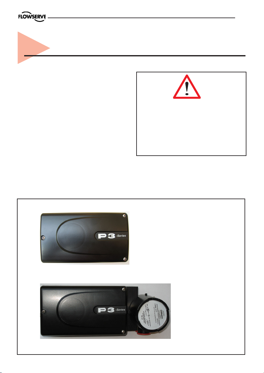
1. Introduction
The PMV P3 is a modular Positioner system designed for use on control valves with
linear motion. The basic unit is the P3 positioner, which is available for single acting.
The I/P converter can be integral, located in
a separate mounted module (Ex), or located
elsewhere. The P3 can be equipped with
connection blocks for pressure gauges to
indicate:
- actuator pressure
- air supply pressure
- input signal pressure
3
Safety instruction
Read the safety instructions in this
manual carefully before using the product.
The installation, operation, and
maintenance of the product must be done
by staff with the necessary training and
experience.
PMV P3 basic unit
PMV P3 with
explosion proof I/P
Page 4

4
2. Storage
General
The PMV positioner is a precision instrument. Therefore it is essential that it is
handled and stored in the correct way.
Always follow the instructions below!
N.B. As soon as the positioner is
connected and started, an internal air bleed
will provide protection against corrosion
and prevent the ingress of moisture. For this
reason, the air supply should always be kept
on.
Storage indoors
Store the positioner in its original
packaging. The storage environment must
be clean, dry and cool, (15 to 26°C,
59 to 79°F).
Storage outdoors or for a
longer period
If the positioner must be stored
outdoors, it is important that all the cover
screws are tightened and that all connections
are properly sealed. The unit should be
packed with a desiccant in a plastic bag or
similar, covered with plastic, and not exposed
to sunlight, rain, or snow.
This is also applicable for long-term
storage (more than 1 month) and for long
transport by sea.
Storage in a warm place
When a positioner is stored in a warm
place with a high relative humidity and is
subjected to daily temperature variations, the
air inside the unit will expand and contract.
This means that air from outside the unit
may be drawn into the positioner. Depending
on the temperature variations, relative
humidity, and other factors, condensation and
corrosion can occur inside the unit, which in
turn can give rise to functional disorders or
a failure.
Page 5

3. Design
5
The P3 positioner comprises a basic
module with a single acting valve block. It
also includes a sealed chamber with terminals for the electrical input signals.
The I/P unit can be built into the main
housing (as shown in the figure below) or
I/P
converter
Feedback arm
Feedback spring
located externally (explosion proof), see
section ”Variants”.
The adjusting screws and knobs are
accessible under the removable sealed aluminium cover.
Balance arm
Flapper nozzle
C+
➠
➠
Supply
Input
3-15 psi
Electrical
connection
Figure shows P3 positioner with integral I/P converter and cover removed
Zero position
adjustment
Adjusting screw,
damping
Span
adjustment
Adjusting
screw, gain
Page 6

6
4. Variants
Standard designs
P3/EP3 is available single acting.
I/P converter can be integral or located
elsewhere.
P3
Pneumatic, single acting, to be
connected to an external I/P converter.
EP3, EP3IS
Electro-pneumatic, single , with integral
I/P converter. Intrinsically safe model also
available.
EP3EX
Explosion proof model, I/P converter
located in separate, sealed enclosure.
Optional equipment
P3 / EP3 positioner can be equipped
with connection blocks and pressure gauges
for:
- input signal pressure
- input air supply pressure
- output pressure
P3/EP3
EP3 EX
Page 7
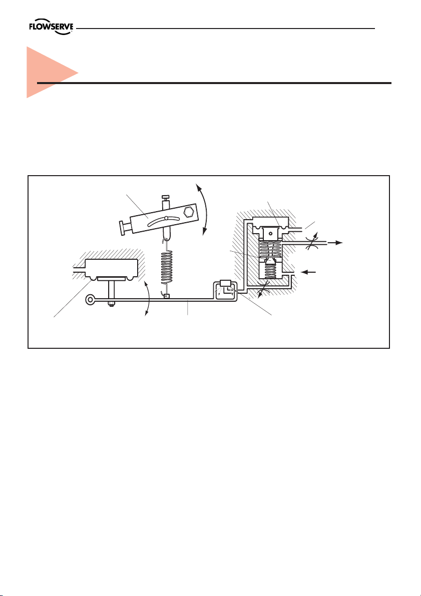
5. Function
General
The P3 positioner operates on the force balance principle. Changes are initiated by the
signal pressure from the I/P converter. The functionality is described briefly below.
Single action
7
Feedback arm
Plug
Signal
pressure
Signal diaphragm Balance arm Flapper nozzle
Increase in signal pressure
When the air pressure on the signal
diaphragm increases, the balance arm is pressed down and the flapper nozzle closes. The
pressure on the relay diaphragm then
increases and the plug valve opens.
Air is now supplied to the actuator, the
spindle movement rotates the feedback arm,
the balance arm is lifted, and the flapper
nozzle opens. The pressure on the relay
diaphragm is reduced and the plug valve
reduces the air flow to the actuator. An
equilibrium position is thus reached and the
valve being controlled is in the desired position.
valve
Decrease in signal pressure
diaphragm is reduced, the balance arm is
lifted and the flapper nozzle opens. The
pressure on the relay diaphragm is then
reduced and the plug valve upper seal opens
and vents.
and its spindle moves. The actuator
movement goes back through the arm
mechanism (see figure) to the positioner
spindle, which rotates the feedback arm. The
balance arm is now lowered by the reduced
spring force and closes the flapper valve. An
equilibrium position is thus reached and the
valve being controlled is in the desired position.
Relay
diaphragm
Venting
When the air pressure on the signal
Air is now ventilated from the actuator
To/from
actuator
Air
supply
Page 8
8
6. Installation
Air supply requirements
Max. air supply pressure, see the section
Technical Data on page 20.
The supply air must be free from
moisture, water, oil, and particles.
The supply air must be dried or be treated
in such a way that its dew point is at least
10°C (18°F) below the lowest expected
ambient temperature.
Before the air supply is connected to the
positioner, we recommend the hose is opened
freely for 2 to 3 minutes to allow any contamination to be blown out. Direct the air jet
into a large paper bag to trap any water, oil,
or other foreign materials. If this indicates
that the air system is contaminated, it should
be properly cleaned.
To ensure a stable and problem-free ope-
ration, we recommend the installation of a
filter/pressure regulator <40µ as close to the
positioner as possible.
WARNING. Do not direct the
open air jet towards people or
objects because it may cause
personal injury or damage.
Poor air quality is the main source of
problems in pneumatic systems.
Page 9

Mounting according to IEC 534-6
9
N.B. If the positioner is installed in a
hazardous environment, it must be of a
type approved for this purpose.
The positioner has an ISO F05 footprint
(A). The holes are used to attach it to the
mounting bracket (B), which is suitable for
most types of linear actuators.
The arm (C) is graduated in mm and
AB
inches. The scale is used to adjust the pin
(D) so its position corresponds to the stroke
of the valve stem.
It is important that the positioner’s
spindle and the arms, that transfer the
actuator movements, are correctly mounted.
Any tension between these parts can cause
incorrect operation and abnormal wear.
C D
Page 10

10
Mounting instructions for P3/EP3 with mounting kit 30168S
Page 11

Connections
11
Air:
Port S Supply air
Port C+ Connection to actuator
Port IPPneumatic input signal
(external I/P)
Electrical connection
Port I
E
Dimensions
Air connections: 1/4" NPT alt. G 1/4"
Electrical connection: M20 x 1.5 alt.
NPT 1/2"
Loctite 577 or equivalent is
recommended as a sealant.
Direct / Reverse function
It is simple to adapt the positioner for
direct or reverse function. Unscrew the
flapper valve nozzle and reverse it, and
change the mounting on the actuator. See
figure page 12.
Electric input signal
4-20 mA
Data for air and electrical
connections, see section
Technical Data on page 20.
Flapper valve position
➠
C+
➠
Supply
Input
3-15 psi
Page 12

12
Single action positioner
Actuator with closing spring, flapper
nozzle set for reverse function
When the signal from the I/P unit
increases, the pressure C+ to the actuator is
increased. The valve stem moves upwards.
Actuator with closing spring, flapper
nozzle set for direct function
When the signal from the I/P unit
increases, the pressure C+ to the actuator is
reduced. The spring forces move the valve
stem downwards.
S
C+
S
C+
Actuator with opening spring, flapper
nozzle set for reverse function
When the signal from the I/P unit
increases, the pressure C+ to the actuator is
increased. The valve stem moves
downwards.
Actuator with opening spring, flapper
nozzle set for direct function
When the signal from the I/P unit
increases, the pressure C+ to the actuator is
reduced. The spring forces move the valve
stem upwards.
S
C+
S
C+
Page 13

Electrical connections
On positioners with an integral I/P unit,
the electric cables are connected to the
terminals as shown in the figure.
Terminals in
positioner EP3
+
–
13
Output signal
from controller
+
–
Warning! In a hazardous
Hazardous areas
environment where there is a
risk of explosion, electrical
connections must comply
with the relevant regulations.
copies of certificates for hazardous
approvals.
Model code
A= Model no
PP3XX Linear positioner, Pneumatic
EP3XX Linear positioner, Electropneumatic
EP3IS Linear positioner, Electropneumatic, Intrin.Safe ATEX, IEC
EP3EX Linear positioner, Electropneumatic, Explosion proof ATEX, IEC, FM
B= Function
S Single acting
C= Connections Air - Electrical
M 1/4" NPT - M20x1,5
N 1/4" NPT - 1/2" NPT
D= Surface treatment
U Powder epoxy, black
E= Spindle
05Male dia. 10 mm
39Male D type incl nut
F= Cover
PV PMV cover, black, no indicator
G= Input signal
3 3-15 psi
4 4-20 mA
H= Temperature
Z -40 to + 85 deg C
I= Option
X No gauge block
M Gauge manifold 1/8" G
N Gauge manifold 1/8" NPT
P3 - U- PV- Z
Please see www.pmv.nu/products/ for
PP3 EP3
Signs
Logotype
II 2G Ex ia IIC T6/T5/T4
NEMKO 08ATEX1144X
Intrinsically safe when installed
according to document: IP-653
Type: E5-IS
Input Signal:
Input Pressure:
Output Pressure:
Temp. Range:
Action:
Flowserve Sweden, Palmstierna International Solna Sweden
www.flowserve.com
36
Type
0470
25
Prod. year:xxxx
Page 14

14
Control drawing
Page 15

7. Adjustments
Gain
Default settings
The positioner is supplied from the
factory with default settings.
If the settings have been changed, the
default settings can be reset as follows:
• Apply an input signal equivalent to maximum stroke (100%).
• Screw in (clockwise) the setting screw A
for gain to its bottom position.
• Unscrew (counter clockwise) the same
screw until the actuator is at max. stroke and
then a further 1/4 of a turn.
• Press on the flapper nozzle lightly (see
arrow) to ensure that it is sealing properly.
• Adjust the input signal to approx. 50%. If
resonance occurs, turn the setting screw A
counter clockwise a little more. The
adjusting screw for damping B can also be
screwed in a little if necessary. However,
this will slow down the actuator movements.
15
B
➞
A
D
Setting the zero position and span
If the zero position and span have been
changed, adjust them as follows:
• Apply an input signal equivalent to the zero
position.
• Turn the setting screw C for zero position
until the actuator is at its zero position.
• Apply the maximum input signal.
• Turn the adjusting screw D for range until
the actuator moves to max. stroke
• Adjust the input signal again to minimum
and check the zero position.
C
Page 16

16
8. Maintenance/service
When service or rebuilding is required,
it may be necessary to remove and refit
various parts of the positioner. This is
described on the following pages.
Valve block
The valve block is mounted on the base
with three screws. It is sealed against the air
ducts in the base with O-rings.
Remove the valve block as follows:
• Remove the spring from its attachment hole
A in the balance arm.
• Unscrew the screws holding the block assy.
Cleanliness is essential when working
with the positioner. Contamination in
the air ducts will lead to operational
disturbances. Do not disassemble the
unit further than that described here.
Do not take the valve block apart
because its function will be impaired.
Do not remove any screws other than
those described here.
A
• Lift the lower edge of the valve block and
pull it away from the base in the direction of
the arrow in the figure.
• Check all the O-rings on the rear side of
the valve block and replace if necessary.
• Refit in the reverse order.
Page 17

Flapper nozzle
The flapper valve holder can be mounted
in two different ways, depending on the
required function. This is described on page
11. Change the function or replace the Orings as follows:
• Unscrew the screws C and D and remove
the holder E. Check both the O-rings and
replace them if necessary.
• Replace the holder in the desired position
and tighten the screws.
17
C
E
D
Gain screw
The sleeve F can be unscrewed to replace
the O-ring G. Let the adjusting screw remain
in the sleeve.
Integral I/P converter
The I/P converter can be removed if it is
necessary to replace it, to replace the O-rings,
or to rebuild the positioner.
• First unscrew the two screws H that hold
the terminal block. Release part of the rubber
seal so that the cables to the terminal block
can be pulled free from the grommet and the
terminal block can be pulled through.
• Remove the I/P unit with its cable and terminal block.
• Replace the O-rings if necessary and refit
the I/P unit or the rebuilding parts.
F
G
H
Page 18

18
Feedback arm / Spindle
The feedback arm is mounted on the
spindle with a friction clutch comprising
several disc springs. Remove the feedback
arm/spindle as follows:
• Remove the circlip J, the washer K behind
it, and the O-ring L.
• Release the spring from its upper
attachment M.
• Pull out the spindle with the feedback arm.
Remove the feedback arm as follows:
• Clamp the spindle in such a way that its
surfaces cannot be damaged.
• Undo the bolt N and remove the feedback
arm and the seven disc springs O.
• Refit in the reverse order. The disc springs
O must be fitted in the way shown in the
figure below. Lubricate the O-ring L with
silicone grease.
J, K, L
M
• Check whether there is any play on the
spindle. If so, replace the teflon bushes P.
J K L O
PN
Page 19

9. Trouble shooting
19
Fault symptom
Change in input signal to positioner does
not affect actuator position.
Change in input signal to positioner makes actuator move to its end position.
Inaccurate positioning.
Action
• Check air supply pressure and connection
between positioner and actuator.
• Check input signal to positioner.
• Check output signal from I/P converter.
• Check mounting and connections of positioner and actuator.
• Check function of diaphragm block.
• Check input signal.
• Check mounting and connections of positioner and actuator.
• Uneven air supply pressure.
•Uneven input signal.
• Wrong size of actuator being used.
• High friction in actuator/valve package.
• Excess play in actuator/valve package.
• Excess play in mounting of positioner
on actuator.
• Defect or leaking diaphragm block.
Page 20

20
10. Technical data
Common data
Repeatability <0,3%
Air delivery Supply at 600 kPa 125 nl/min
Air delivery Exhaust at 600 kPa 125 nl/min
Air supply pressure range 140-600kPa
Gain % / % acc. to ISA S75 5 to 30 %/%
Temperature range -40°C to +85°C
Temperature sensitivity < 0.4% per 10°C
Stroke length 6 - 60 mm, option 3 mm
Other data
P3
Linearity <±1%
Hysteresis + Deadband <0.5%
Deadband <0.15%
Air consumption (depending on gain setting) 2-8 nl/min
Supply pressure sensitivity <0.20%
Input signal 0.2 - 1 bar (3 - 15 psi)
EP3
Linearity <±1.5%
Hysteresis + Deadband <1%
Deadband <0.2%
Air consumption (depending on gain setting) 4-10 nl/min
Supply pressure sensitivity <0.3%
Input signal 4 - 20 mA
EP3EX
Linearity <±1.5%
Hysteresis + Deadband <1%
Deadband <0.2%
Air consumption (depending on gain setting) 4-10 nl/min
Supply pressure sensitivity <0.3%
Input signal 4 - 20 mA
Page 21

21
Page 22

22
11. Spare Parts List
1
4 3 2
Page 23

Pos. Part no. Description
1 E5-STD I/P Converter general purpose
1 E5-IS I/P Converter intrinsically safe
2 E3-EX I/P Converter explosion proof, incl bracket
3 P3-SP15 Air relay module, single acting
4 7-SP25B Cover incl screws
23
Page 24

Palmstierna International AB
Korta Gatan 9
SE-171 54 Solna
SWEDEN
Tel: +46 (0) 8 555 106 00
Fax: +46 (0) 8 555 106 01
E-mail: infopmv@flowserve.com
www.pmv.nu
Germany
Flowserve
Sperberweg 16
D-41468 Neuss
GERMANY
Tel: +49 (0) 2131 795 74 80
Fax: +49 (0) 2131 795 74 99
E-mail: pmvgermany@flowserve.com
UK
Flowserve
Abex Road
Newbury, Berkshire, RG14 5EY
UK
Tel: +44 (0) 1635 46 999
Fax: +44 (0) 1635 36 034
E-mail: pmvukinfo@flowserve.com
Scandinavia
Palmstiernas Svenska AB
Box 21
663 21 Skoghall
Sweden
Tel: +46 (0)54 52 14 70
Fax: +46 (0)54 52 14 42
e-mail: info@palmstiernas.se
Italy
Flowserve Spa
Via Prealpi, 30
20032 Cormano (Milano)
ITALY
Tel: +39 (0) 2 663 251
Fax: +39 (0) 2 615 18 63
E-mail: infoitaly@flowserve.com
USA, Mexico
PMV-USA
1440 Lake Front Circle, Unit 160
The Woodlands, TX 77380
USA
Tel: +1 281 292 7500
Fax: +1 281 292 7760
E-mail: pmvusa@flowserve.com
Canada
Cancoppas Limited
2595 Dunwin Drive, Unit 2
Mississuga, Ont L5L 3N9
CANADA
Tel: +1 905 569 6246
Fax: +1 905 569 6244
E-mail: controls@cancoppas.com
Asia Pacific Headquarters
Flowserve Pte Ltd.
No. 12 Tuas Avenue 20
REPUBLIC OF SINGAPORE 638824
Tel: +65 (0) 687 98900
Fax: +65 (0) 686 24940
E-mail: fcdasiaprocess@flowserve.com
South Africa
Flowserve
Unit 1, 12 Director Road
Spartan Ext. 2
1613 Kempton Park, Gauteng
SOUTH AFRICA
Tel: +27 (0) 11 397 3150
Fax: +27 (0) 11 397 5300
The Netherlands
Flowserve Flow Control Benelux
B.V
Postbus 1501
4700 Roosendaal
THE NETHERLANDS
Tel: + 31 (0)165 598898
Fax: + 31 (0)165 555670
China
Flowserve
Hanwei Building
No. 7 Guanghua Road
Chao Yang District
100004 Beijing
CHINA
Tel: +86 (10) 6561 1900
Fax: +86 (10) 6561 1899
FCD PMENIM0012-02
 Loading...