

Page 1
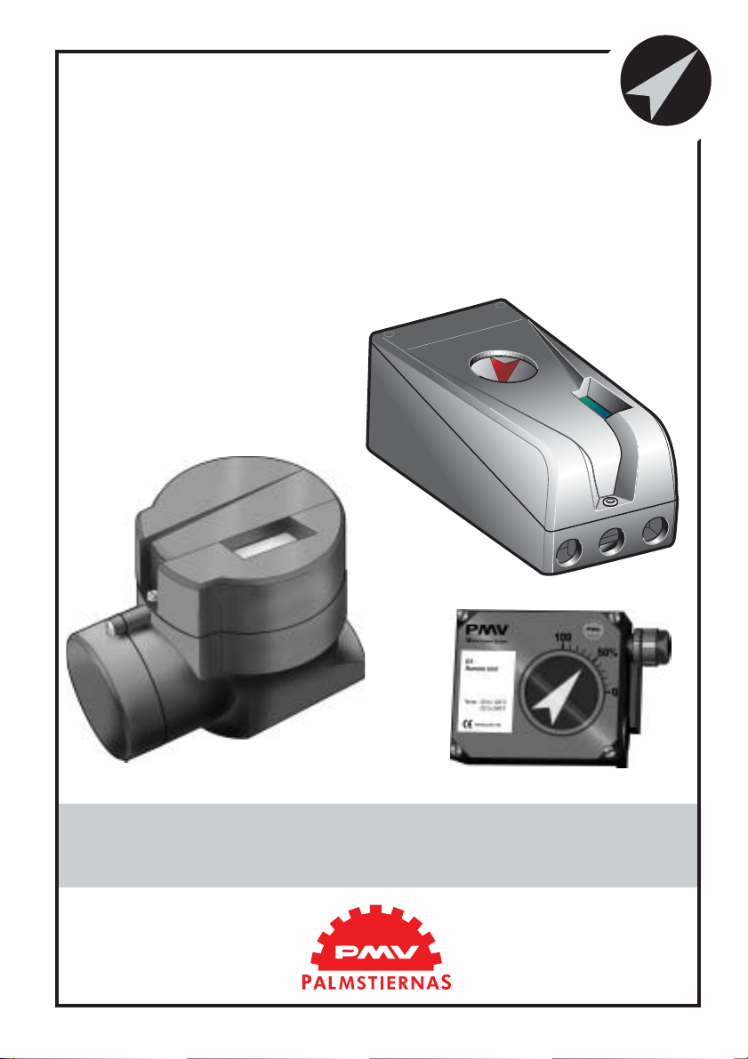
D3
Digital
Positioner
Manual
Page 2

Contents
1.Introduction ...................................................................................................... 3
Safety instruction................................................................................................ 3
2. Storage .............................................................................................................. 4
General ............................................................................................................... 4
Storage indoors ................................................................................................... 4
Storage outdoors or for a longer period.............................................................. 4
Storage in a warm place ..................................................................................... 4
3. Design................................................................................................................ 5
4. Variants............................................................................................................. 6
5. Function............................................................................................................ 7
Double action function ....................................................................................... 7
Single action function......................................................................................... 7
6. Installation........................................................................................................ 8
Air supply requirements ..................................................................................... 8
Mounting ............................................................................................................ 9
Connections ........................................................................................................ 10
Air....................................................................................................................... 10
Electrical connection .......................................................................................... 10
Dimensions ......................................................................................................... 10
Single action positioner (Direct function) .......................................................... 11
Actuator with closing spring............................................................................... 11
Actuator with opening spring ............................................................................. 11
Double action positioner (Direct function)......................................................... 11
Double action actuator........................................................................................ 11
Electrical connections......................................................................................... 12
7. Control............................................................................................................. 14
Menus and pushbuttons ...................................................................................... 14
Other functions ................................................................................................... 14
Menu indicator.................................................................................................... 15
Menus ................................................................................................................. 15
Changing parameter values ................................................................................ 15
Menu system....................................................................................................... 16
First start ............................................................................................................. 17
8. Maintenance/service ........................................................................................ 37
Disassembling PMV D3 ..................................................................................... 37
Silencer ............................................................................................................... 39
Spindle adapter ................................................................................................... 39
Potentiometer...................................................................................................... 40
Transmitter boards.............................................................................................. 41
Disassembling PMV D3 Ex................................................................................ 44
Filter change ....................................................................................................... 45
Converting for remote control ............................................................................ 46
9. T r ouble shooting .............................................................................................. 47
10. Technical data ................................................................................................ 48
Certificates.......................................................................................................... 48
11. Spare parts ..................................................................................................... 56
2
Page 3
1. Introduction
The PMV D3 is a digital positioner designed primarily for controlling adjustable
valves.
The positioner can be used with single or
double action actuators with either rotary or
linear movement.
The D3 can be equipped with modules
for feedback, limit switches, and a pressure
gauge block.
The modules can be factory assembled
before delivery or fitted later.
The modules for feedback and limit
switches can contain the following:
Feedback 4-20 mA and one of the
following functions:
- Two mechanical contacts
- Two reed switches
- Two inductive sensors, DIN 19234
Safety instruction
Read the safety instructions in this manual carefully before using the product. The
installation, operation, and maintenance of the product must be done by staff with the
necessary training and experience. If any questions arise during installation, contact
the supplier/sales office before continuing work.
Warning
• The valve package moves when in operation and can cause personal injury or damage
if handled incorrectly.
• If the input signal fails or is switched off, the valve moves quickly to its end position.
• If the compressed air supply fails or is turned off, fast movements can occur.
• The valve is not controlled by the input signals when in the Out of service mode. It
will open/close in the event of a leak.
• If a high value is set for Cut off, fast movements can occur.
• When the valve is controlled in the Manual mode, the valve can move quickly.
• Incorrect settings can cause self-oscillation, which can lead to damage.
Important
• Always turn of f the compressed air supply before removing or disconnecting the air
supply connection or the integral filter. Remove or disconnect with care because C- is
still under pressure even after the air supply is turned off.
• Always work in an ESD protected area when servicing the PCB´s. Make sure the
input signal is switched off.
• The air supply must be free from moisture, water, oil and particles.
3
Page 4

2. Storage
General
The PMV positioner is a precision instrument. Therefore it is essential that it is
handled and stored in the right way . Always
follow the instructions below!
N.B. As soon as the positioner is
connected and started, internal air leakage
will provide protection against corrosion
and prevent the ingress of moisture. For this
reason, the air supply pressure should
always be kept on.
Storage indoors
Store the positioner in its original
packaging. The storage environment must
be clean, dry, and cool (15 to 26°C, 59 to
79°F..
Storage outdoors or for a longer
period
If the positioner must be stored
outdoors, it is important that all the cover
screws are tightened and that all connections
are properly sealed. The unit should be
packed with a desiccant (silica gel) in a
plastic bag or similar, covered with plastic,
and not exposed to sunlight, rain, or snow.
This is also applicable for long-term
storage (more than 1 month) and for long
transport by sea.
Storage in a warm place
When the positioner is stored in a warm
place with a high relative humidity and is
subjected to daily temperature variations, the
air inside the unit will expand and contract.
This means that air from outside the unit
may be drawn into the positioner. Depending
on the temperature variations, relative
humidity , and other factors, condensation and
corrosion can occur inside the unit, which in
turn can give rise to functional disorders or
a failure.
4
Page 5
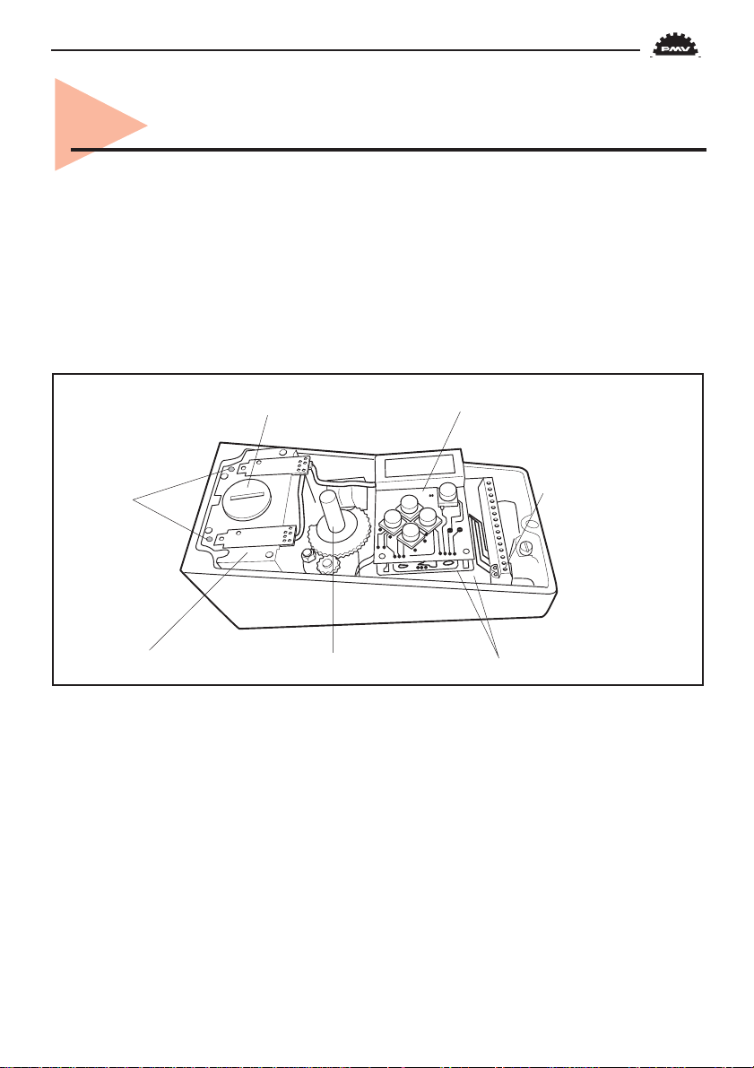
3. Design
The D3 positioner contains:
• Electronic board with microprocessor,
HART modem, display, etc.
• Valve block
• Positional feedback with potentiometer
• Sealed compartment for electrical
connections
Filter Display, control push buttons
Adjustingscrews,
damping
Valve block
Positional feedback Processor and motherboard
The push buttons and display are
accessible underneath the aluminium
cover, which is sealed with an O-ring.
The figure shows the D3 with the cover
removed.
Terminal block
5
Page 6

4. Variants
D3 270°deg.
D3 up to 270° deg for extended travel
range is available. It features all benefits and
options similar to the standard D3.
Communication with HART or Profibus is
possible.
D3 Explosion proof
The digital positioner D3 is available in
explosion proof enclosure. It features the
same easy to use user interface for local configuration as D3. Communication with Hart
or Profibus is possible.
Further features are gauge ports and local
graphic LCD display.
D3 Intrinsically safe
The digital positioner D3 is available in
intrinsically safe version for installation in
hazardous areas. It features the same easy to
use user interface for local configuration as
D3. Communication with HART or Profibus
is possible. It features all benefits and options
similar to the Standard D3 positioner, gauge
block, local graphic LCD display and feedback option etc.
D3 remote mounted
The D3 with remote mount is now
available on the market for order. This version is suitable for installations in severe
applications e.g. vibrations, high or low
temperature corrosive environment, high
mountings or difficult of access, etc. A flat
or dome style indicator can be fitted on the
feedback box installed on the actuator. Max
recommended distance between D3 and
remote unit is 5 m.
6
Page 7
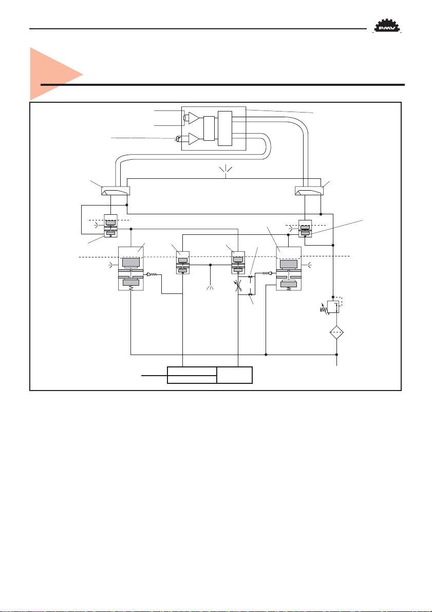
5. Function
Control signal 4 - 20 mA
Potentiometer
Piezo-valve 2
C
D
Actuator
E
C– C+
➾
Venting
Double action function
The control signal and the feedback
potentiometer position are converted to digital signals that are processed with a PID
algorithm in the microprocessor. This provides control signals to the two piezo-valves.
The two piezo-valves are closed in the
schematic diagram above and have no effect
on the valves A and D. Air from the pressure
regulator is lead through the open valve A to
the valve B, which opens. The supply
pressure can now pass through valve B to
the actuator via H. The actuator then moves
in the direction of the arrow. At the same
Signal converter
and
microprocessor
Venting
B
F
time, air from valve A keeps valve C open
and allows venting of the actuator.
A closes but valve D opens and controls
valves E and F to that the actuator moves in
a direction opposite to the arrow. When only
piezo-valve 1 is open, the actuator is
stationary.
G
H
Air supply 2 - 6 bar
When both the piezo-valves open, valve
Piezo-valve 1
A
Diaphragm
1.2 bar
Pressure
regulator
Replaceable
Filter
Single action function
Valve B is used for the supply air and
valve F for venting.
7
Page 8
6. Installation
Tubing
Use tubes with an inner diameter of mi-
nimum 6 mm (1/4”).
Air supply requirements
Max. air supply pressure, see the section
Technical Data, Section 10.
The air supply must be free from
moisture, water, oil, and particles.
Before the air supply is connected to the
positioner, we recommend the hose is opened
freely for 2 to 3 minutes to allow any contamination to be blown out. Direct the air jet
into a large paper bag to trap any water, oil,
or other foreign materials. If this indicates
that the air system is contaminated, it should
be properly cleaned.
The air must come from a refrigeration
dried supply or be treated in such a way that
its dew point is at least 10°C (18°F) below
the lowest expected ambient temperature.
To ensure a stable and problem-free air
supply, we recommend the installation of a
filter/pressure regulator <40µ as close to the
positioner as possible.
WARNING! Do not direct the
open air jet towards people or
objects because it may cause
personal injury or damage.
Poor air supplies are the main source
of problems in pneumatic systems.
8
Page 9
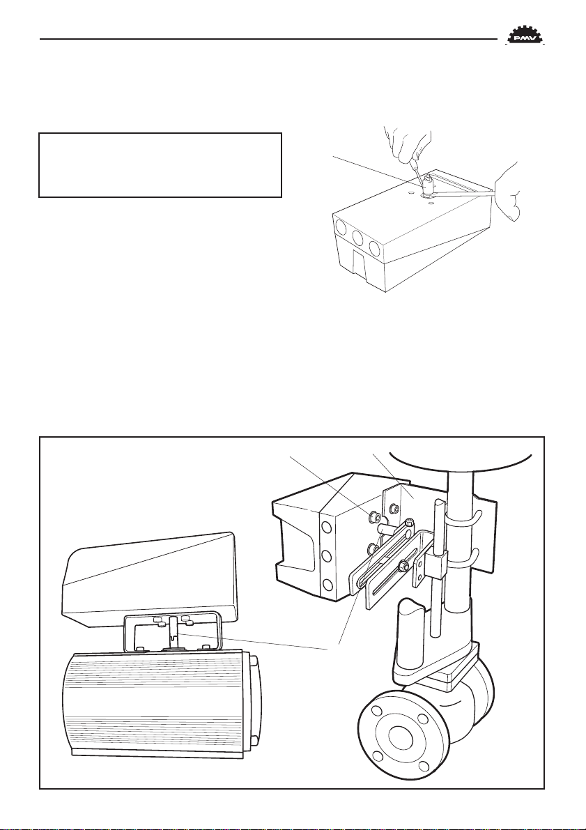
Mounting
N.B. If the positioner is installed in a
hazardous environment, it must be of a
type approved for this purpose.
The D3 positioner has an ISO F05
footprint, A. The holes are used to attach it
to the mounting bracket B, which is suitable
for most types of linear actuator.
The spindle adapter C can be changed to
suit the actuator in question.
Remove the existing adapter using two
screwdrivers. Check that the spring ring on
the positioner spindle is undamaged and fit
the new adapter.
Assembly examples
C
It is important that the positioner’s spindle
and the arms, that transfer the actuator
movements, are correctly mounted. Any tension between these parts can cause incorrect
operation and abnormal wear.
A B
C
Rotary movement Linear movement
9
Page 10
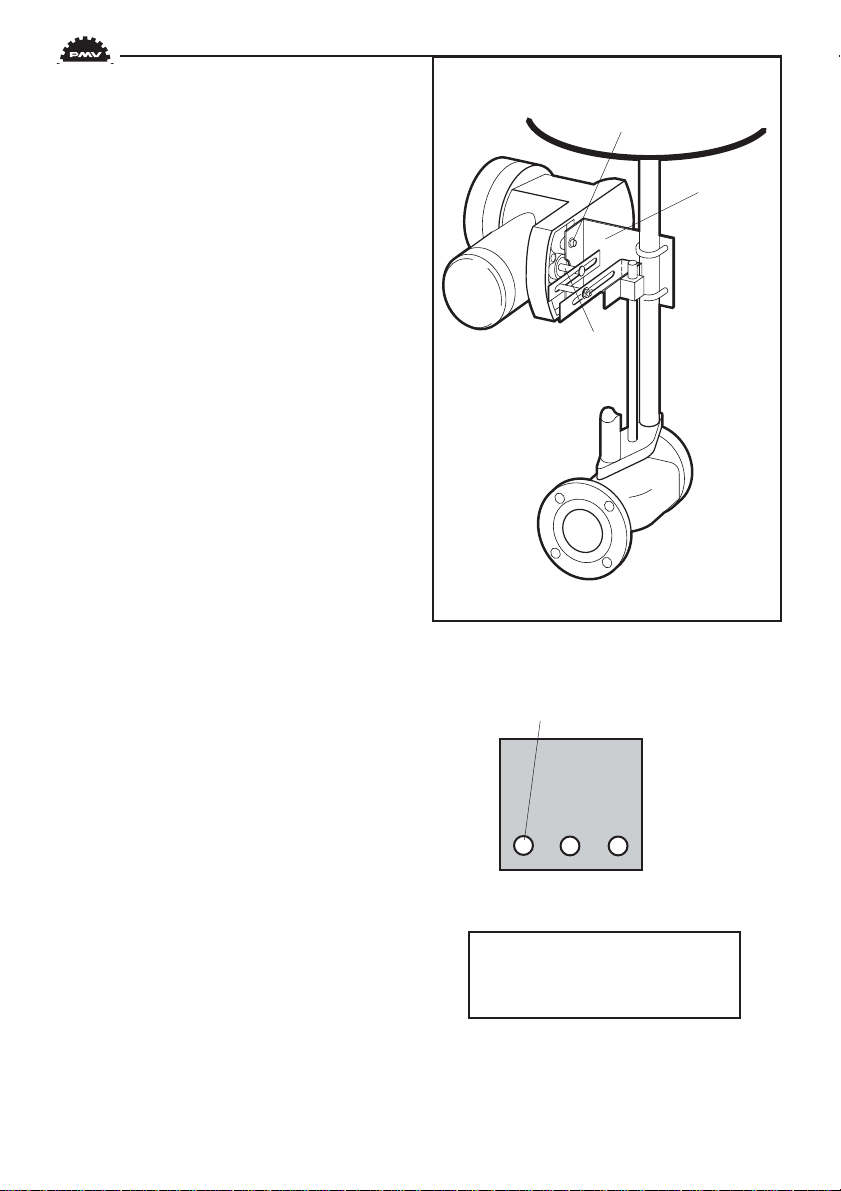
The D3 Ex positioner has an ISO F05
footprint, A. The holes are used to attach it
to the mounting bracket B, which is suitable
for most types of linear actuators.
The spindle adapter C can be changed to
suit the actuator in question, see previous
page.
A
B
C
Connections
Air:
Port S Supply air, 2-7 bar
Port C+ Connection to actuator
Port C- Connection to actuator
(only for double action)
Electrical connection
See page 12, 13.
Dimensions
Air connections:
1/4" NPT alt. G 1/4"
Electrical connection:
M20 x 1.5 alt. NPT 1/2"
Loctite 577 or equivalent is recommended
as a sealant.
10
Must be plugged when converting to
single action function.
C– S C+
For data for air and electrical
connections, see section
Technical Data on page 48.
Page 11
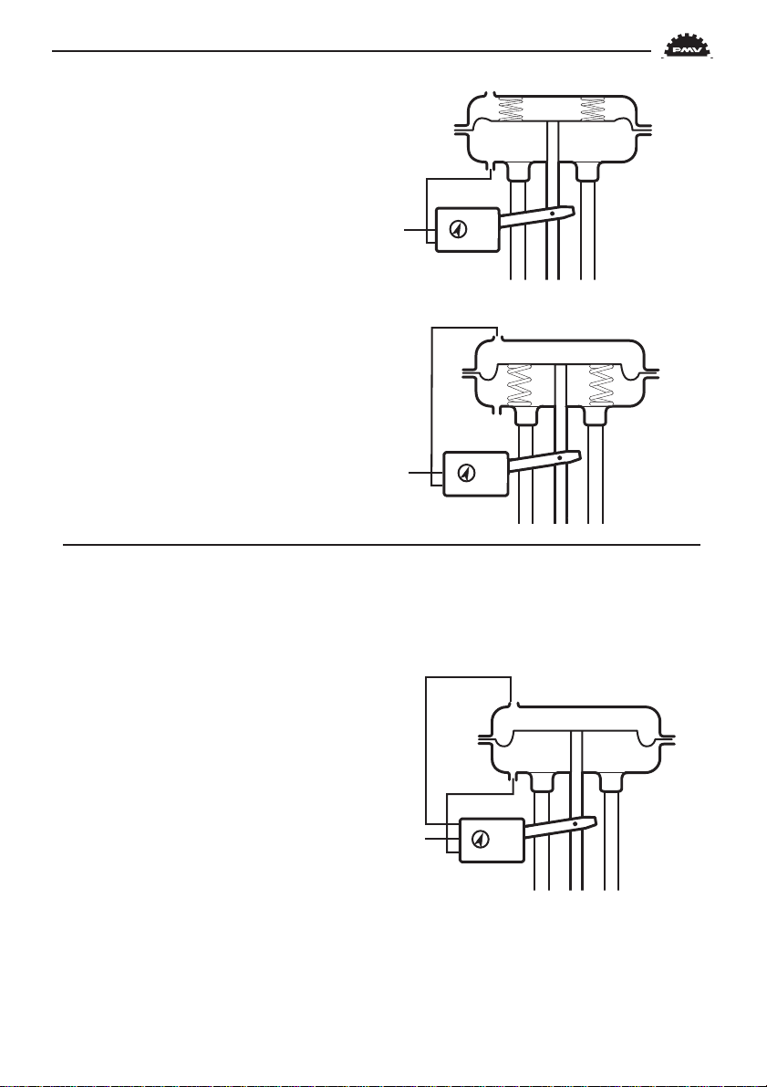
Single action positioner
(Direct function)
Actuator with closing spring
When the control signal increases, the
pressure C+ to the actuator is increased. The
valve spindle moves upward and rotates the
positioner spindle counter-clockwise. When
the control signal drops to zero, C+ is vented
and the valve closes.
Actuator with opening spring
When the control signal increases, the
pressure C+ to the actuator is reduced. The
springs press the valve spindle upward and
the positioner spindle rotates counterclockwise. When the control signal drops to
zero, C+ is vented and the valve opens.
Double action positioner
(Direct function)
C–
S
C+
C–
S
C+
Double action actuator
When the control signal increases, the
pressure C+ to the actuator is increased. The
valve spindle is pressed upward and rotates
the positioner spindle counter-clockwise.
When the control signal is reduced, the
pressure C- to the actuator increases and the
valve spindle is pressed downward. If the
control signal disappears, the pressure goes
to C-, C+ vents, and the valve closes.
C–
S
C+
11
Page 12
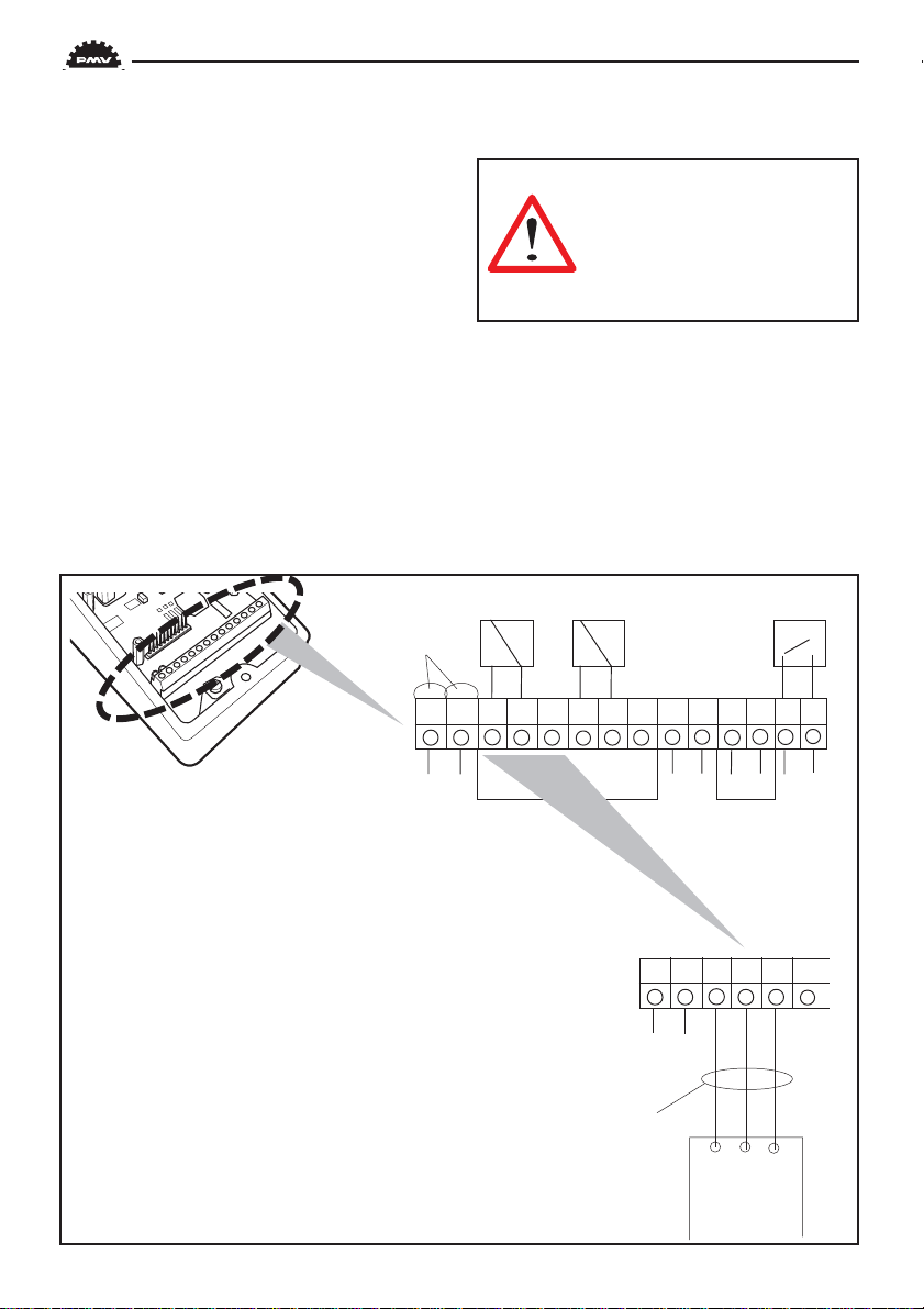
Electrical connections
The diagrams show the terminal blocks
in D3 and D3 Ex.
Remote unit
The remote unit shall be connected
between terminals3, 4 and 5 in the D3 and 3,
4 and 5 in the remote unit. Use a shielded
cable and ground it in the D3 only. Max
recommended distance between D3 and
remote unit: 5 m.
Note! When converting D3/D3 Ex for use
with remote unit, some changes have to be
done inside the positioner, see Section 8.
When installing D3 Intrinsically safe unit, always consider cdwg D3-70.
HARTconnection
1234567891011 12 13 14
Warning! In a hazardous
environment where there is a
risk of explosion, electrical
connections must comply with
the relevant regulations.
D3
The terminal block (below) for the positioner is accessible when the aluminium cover
and inner cover is removed, see Section 8.
12
+ – + – + – + –
Option
1 4-20 mA + input signal
2 4-20 mA – input signal
3 Switch 1 NO
4 Switch 1 NC
5 Switch 1 COM
6 Switch 2 NO
7 Switch 2 NC
8 Switch 2 COM
9 AUX input 4-20 mA +
10 AUX input 4-20 mA –
11 4-20 mA + Feedback, 10-28 V DC
12 4-20 mA – Feedback, 10-28 V DC
13 Alarm output +
14 Alarm output –
Connecting a
remote unit
123456
+ –
Shielded cables,
grounded on the D3
345
Remoteunit
Page 13
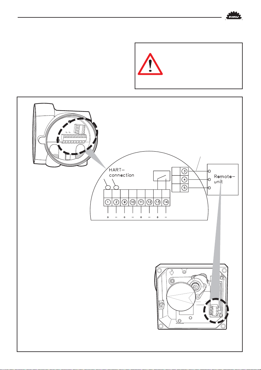
D3 Ex
The terminal block (below) for the positioner is accessible when the terminal cover
is removed, see Section 8.
Warning! In a hazardous
environment where there is a
risk of explosion, electrical
connections must comply with
the relevant regulations.
1 4-20 mA + input signal
2 4-20 mA – input signal
3 (Remote unit)
4 (Remote unit)
5 (Remote unit)
9 AUX input 4-20 mA +
10 AUX input 4-20 mA –
11 4-20 mA + Feedback, 10-28 V DC
12 4-20 mA – Feedback, 10-28 V DC
13 Alarm output +, 8-28 V DC
14 Alarm output –, 8-28 V DC
Optional
13
Page 14

7. Control
Menus and pushbuttons
The positioner is controlled using the five
pushbuttons and the display, which are
accessible when the aluminium cover is
removed.
For normal functioning, the display
shows the current value. Press the ESC
button for two seconds to display the main
menu.
Use the pushbuttons to browse
through the main menu and the sub-menus.
The main menu is divided up into a basic
menu and a full menu, see page 16.
Other functions
ESC
Exit the menu without making any changes
(as long as any changes have not been
confirmed with OK).
FUNC
To select function and change parameters.
OK
To confirm selection or change of parameters.
MENU INDICATOR
Displays the position of the current menu
row in the menu.
14
OUT OF SERVICE
MANUAL
BASIC MENU
MAN/AUTO
UNPROTECTED
ESC FUNC
IN SERVICE
The positioner is following the input signal. This is the normal status when the positioner is working.
OUT OF SERVICE
The positioner is not following the input
signal. Critical parameters can be changed.
MANUAL
The positioner can be adjusted manually
using the pushbuttons. See section ”Man/
Auto”, page 21”.
UNPROTECTED
Most of the parameters can be changed
when the positioner is in the ”Unprotected”
position. However, critical parameters are
locked when the positioner is in the ”In service” position.
OK
Page 15

Menu indicator
There are indicators at both sides of the
display window and they indicate as follows:
Flashing in position Out of service
FULL MENU
MAN/AUTO
Flashing in position Manual
Displayed in position Unprotected
The indicators on the right-hand side
show the position in the current menu.
Menus
To display the menus you can select:
- Basic menu, which means you can browse
through four different steps
- Full menu, which comprises ten steps. Use
the Shift Menu to browse through the steps
Full Menu can be locked out using a
passcode.
The main menus are shown on the next
page and the sub-menus on the subsequent
pages.
FULL MENU
CALIBRATE
FULL MENU
SHIFT MENU
Changing parameter values
Change by pressing until the desired
figure is flashing.
Press to step to the desired figure.
Confirm by pressing OK.
A change can be undone by pressing the ESC
button, which returns you to the previous
menu.
15
Page 16
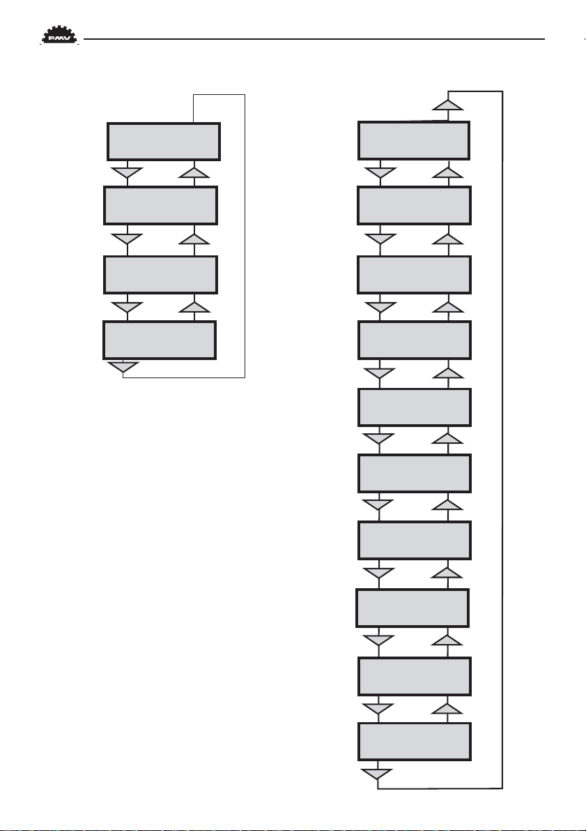
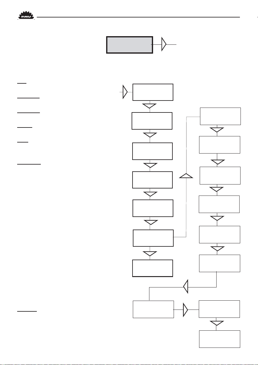
Menu system
BASIC MENU
READ
BASIC MENU
MAN/AUTO
BASIC MENU
CALIBRATE
BASIC MENU
SHIFT MENU
The menus are described
on the following pages.
FULL MENU
READ
FULL MENU
MAN/AUTO
FULL MENU
CALIBRATE
FULL MENU
SHIFT MENU
FULL MENU
PROTECTION
FULL MENU
STATUS
FULL MENU
SETUP
16
FULL MENU
TUNING
FULL MENU
ALARMS
FULL MENU
FACT SET
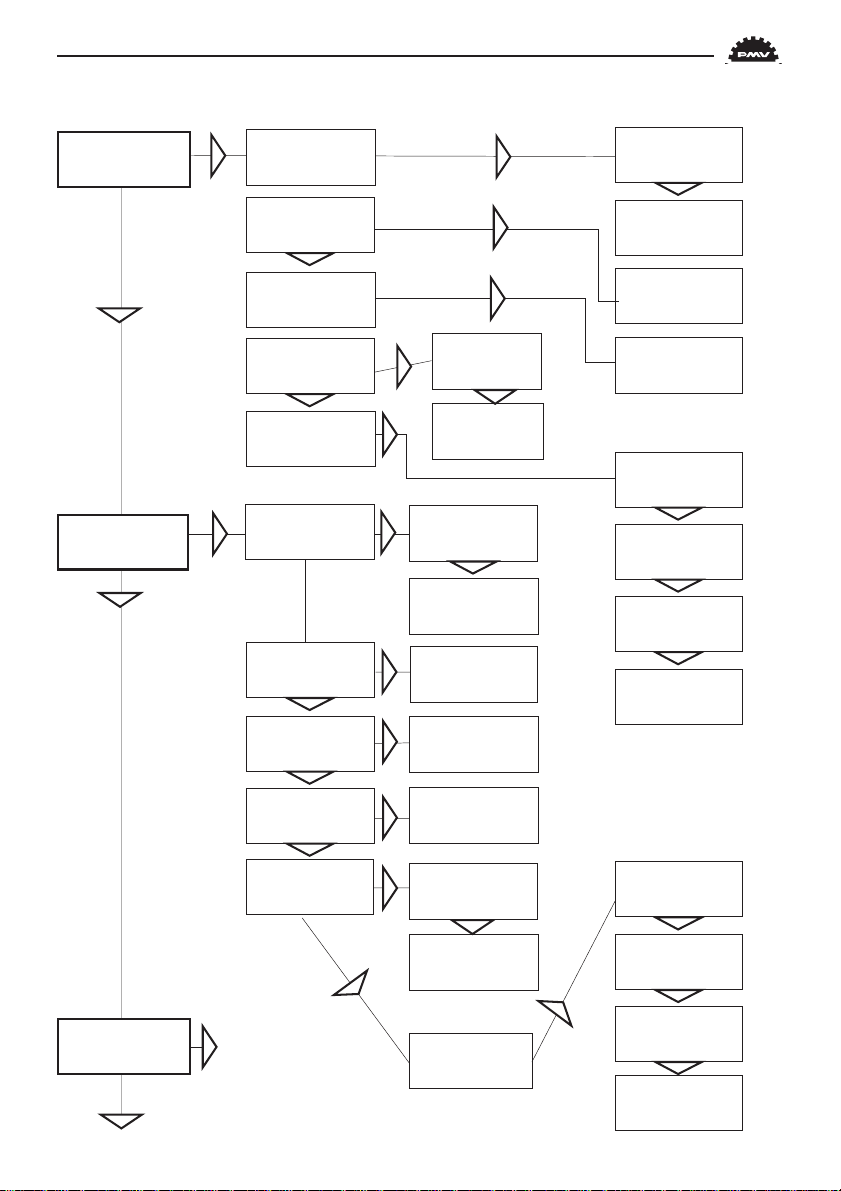
Page 17
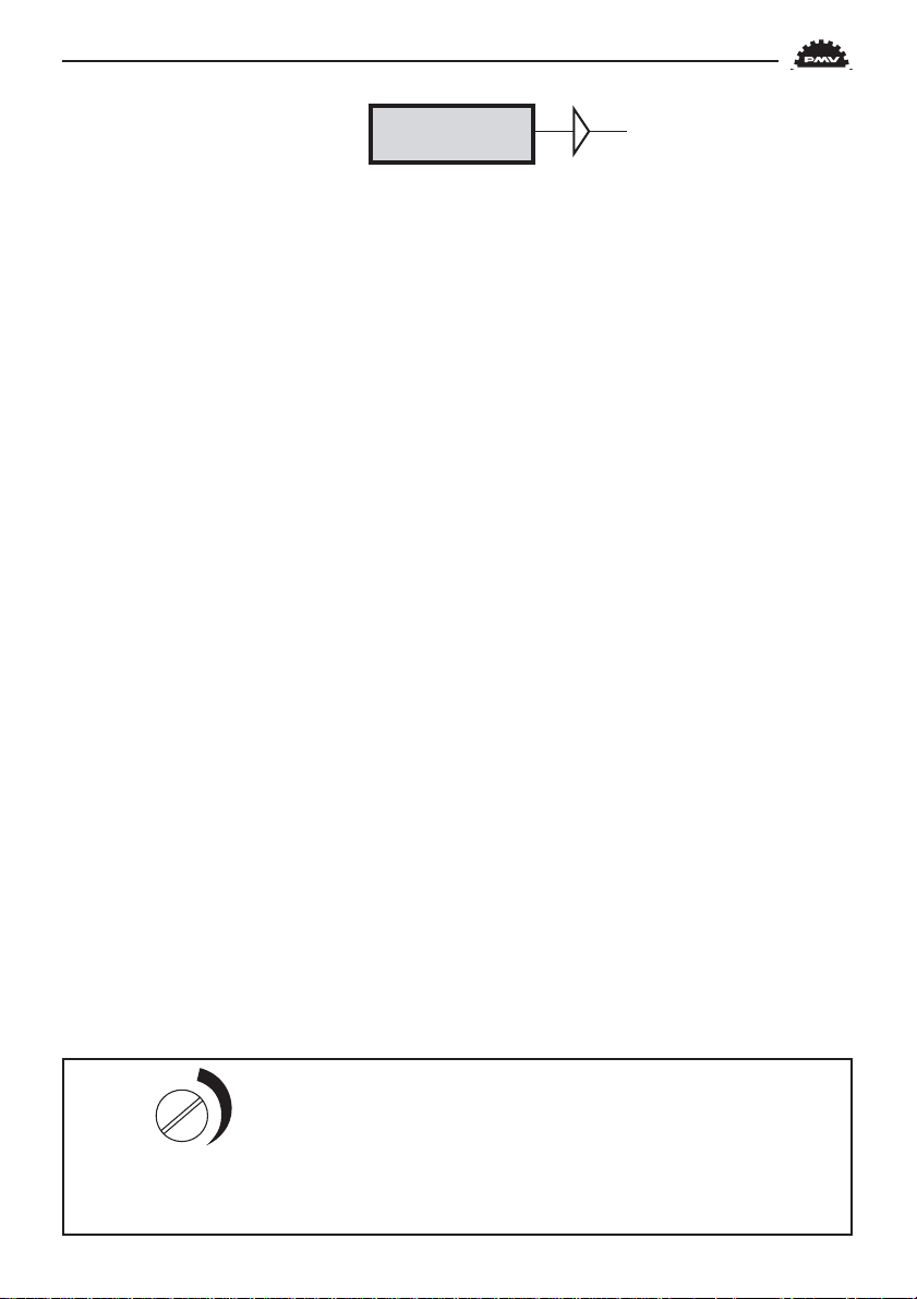
BASIC MENU
CALIBRATE
First start
Calibrate in the basic menu is displayed
automatically the first time the positioner is
connected up, and can be selected from the
basic/main menu at any later time.
A complete calibration takes about 3
minutes and includes end limit calibration,
auto-tuning, leak test, and a check on the
speed of movement. Start the automatic
calibration by selecting Auto-Cal and then
answer the questions on the display by pressing OK or the respective arrow. The menu
is described on the next page.
Calibration error messages
If a fault occurs during calibration, one
of the following error messages can be displayed:
Invalid movement/press ESC to abort
No movement because the air is
incorrectly connected, for example. After the
fault is corrected, the calibration sequence
must be restarted.
Pot unaligned/press ESC to abort
The potentiometer has been set to an illegal value. The potentiomenter is aligned
using the Calibrate - Expert cal - pot Menu.
The calibration sequence must be restarted
after the fault is corrected.
Air leak detected/ESC = abort
OK = go on
An air leak has been detected. The
calibration sequence should be restarted after
the fault is corrected.
Increase C- damper/ESC = abort
OK to retry
Increase C+ damper/ESC = abort
OK to retry
Speed of movement is too fast. Adjust
with the damper screws (see page 5). Press
OK. Repeat the adjustment and press OK
until the speed is correct. If there is an abort,
the calibration sequence must be restarted.
First start, Profibus
Connect the input signal at pos 1 and 2
on the terminal block. See Electrical
connections in the manual.
In the SETUP/Devicedata/Profibus:
change the address from 126 to any number
between 1-125.
Do never use the same number to more
than one unit. Install values in failsafe mode,
for communication when loss of signal.
Calibrate the unit.
GSD files are available at our homepage
www.pmv.nu
C+
(C–)
Clockwise = Increased damping/Less flow
CCW = Decreased damping/Mor e flow
3 revsCCW = Max flow
Note! To much increased damping (low flow)
might cause irregular actuator function.
17
Page 18
BASIC MENU
CALIBRATE
The contents of the menu are shown on the next page. The various menu
texts are described below.
Auto-Cal Auto-tuning and calibration of end positions
Start tune Starts the tuning. Questions/commands are displayed during
calibration. Select the type of movement, function, etc. with
and confirm with OK as shown in the chart on the next
page.
Lose prev value? OK? A warning that the value set previously will be lost (not during
the first auto-tuning).
Actuator? rotating Select for rotating actuator.
Actuator? linear Select for linear actuator.
Actuator single act Select for single act.
Actuator double act Select for double act.
Direction? direct Select for direct function.
Direction? reverse Select for reverse function.
In service? Press OK Calibration finished. Press OK to start positioner functioning.
(If ESC is pressed, the positioner assumes the ”Out of service”
position but the calibration is retained).
TravelCal Calibration of end positions
Start cal Start end position calibration.
Lose prev value? OK? A warning that the previously set value will be lost.
Confirm with OK.
The calibration sequence starts.
In service? Press OK Calibration finished. Press OK to start positioner functioning.
(If ESC is pressed, the positioner assumes the ”Out of service”
position but the calibration is retained).
Perform Setting gain
Normal 100% gain
Perform 50%, 25%,
12%, L, M, S Possibility to select a lower gain in steps.
L, M, S Preset values for L, M, S actuators
Factory set Resets all set values and enters Factory Mode. Should only
be used by authorized staff.
Note. Original P. I. D. will always be shown in display
18
Page 19

CALIBRATE
AutoCal
AutoCal
Start tune
LOSE PREV
OK
VALUE?OK?
CALIBRATE
TravelCal
CALIBRATE
Perform
TravelCal
Start cal
LOSE PREV
VALUE?OK?
OK
Calibration in
progress
IN SERVICE
? Press OK
OK
OK
OK
Actuator?
rotating
Actuator?
linear
OK
OK
Actuator
single act
Actuator
single act
Direction?
direct
Direction?
reverse
Calibration in
progress
IN SERVICE
? Press OK
OK
Perform
normal
OK
OK
CALIBRATE
ExpertCal
All these values are set at the
factory before delivery and
Set point LO: Use the calibrator set to 4 mA
(or set another value on the display). Press OK.
Set point HI: Use a calibrator of 20 mA
(or set another value on the display). Press OK.
Pressure read out only possible on D3 with built
in pressure sensor.
Pressure LO: Use a supply of 2 bar (30 psi)
(or set another value on the display). Press OK.
Pressure HI: Use a supply of 7 bar (105 psi)
(or set another value on the display). Press OK.
Temp: Calibrate using a known temperature.
Aux input LO: Use the calibrator
and a power supply of 4 mA (or set another
value on the display). Press OK.
Aux input HI: Use a supply of 20 mA
(or set another value on the display). Press OK.
Pot: Potentiometer setting, if its position
relative to the gear segment has been changed.
See Section 8.
should not normally be changed.
Full reset: Resets all the set values.
Perform
50%
25%
12%
L
M
S
Perform
Factory set
OK
OK
OK
OK
OK
19
Page 20
The menu contents are shown in the figures on the right and the texts are described below:
BASIC MENU
READ
Current values can be read using the Read Menu and some values can be reset.
Pos Shows current position
READ
Set&pos Set point and position
pos
Set&dev Set point and deviation
Temp Shows current temperature
Aux Shows auxinput signal valve.
External pot or similar
Statistics
n cycles Shows number of movements
(turns)
Acc travel Shows accumulated
movement
mean dev Shows accumulated deviation
in %
runtime Shows accumulated runtime
since last reset
Extr temp Shows extreme min and max
temperature
Histogram Shows position and time for
PV
READ
set&pos
READ
set&dev
READ
temp
READ
aux
READ
Statistics
READ
Alarms
Statistics
n cycles
Statistics
acc travel
Statistics
mean dev
Statistics
runtime
Statistics
extr. temp
Statistics
histogram
Alarms Displays tripped alarms
20
Statistics
Reset stat
Reset stat
yes
Reset stat
no
Page 21

BASIC MENU
MAN/AUTO
The Man/Auto menu is used to change between manual and automatic modes.
The menu contents are shown in the
figures on the right and the various texts are
described below:
AUT, OK = MAN
Positioner in automatic mode
MAN, OK = AUT
Positioner in manual mode
In the MAN mode, the value of POS can
be changed using . The pushbuttons increase/decrease the value in steps.
The value can also be changed in the same
way as for the other parameter values, as
described on page 15.
Other functions
C+ can be fully opened by pressing
and then immediately OK simultaneously.
C- can be fully opened by pressing
and OK simultaneously.
C+ and C- can be fully opened for blowing
clean by pressing and OK
simultaneously.
AUT, OK=MAN
POS= 12,3%
When changing between
MAN and AUT mode, the OK
button must be depressed for 3
seconds.
MAN, OK=AUT
OK
POS= 12,3%
21
Page 22

BASIC MENU
SHIFT MENU
The Shift Menu is used to choose between the basic menu and the full menu.
The menu contents are shown in the
figures on the right and the various texts are
described below:
No Full menu selected.
Yes Basic menu selected.
Full Menu can be locked with a
passcode, see Setup menu.
FULL MENU
PROTECTION
The Write Protect menu is used to protect all essential settings.
The menu contents are shown in the
figures on the right and the various texts are
described below:
Full menu
no
Full menu
yes
PROTECTION
no
OK
OK
OK
No Entered values are not write
protected. ”Unprotected” is
displayed in the lower lefthand corner.
Yes Entered values are write
protected. Passcod needed for
change to No (Applicable
when a passcode has been set
up in SETUP menu).
22
.
PROTECTION
yes
When changing between
Yes and No mode, the OK
button must be depressed
for 3 seconds.
OK
Page 23

FULL MENU
STATUS
The Status Menu is used to select whether or not the positioner is in service.
The menu contents are shown in
the figures on the right and the various
texts are described below:
o o service Not in service. Flashing
indicator in upper lefthand corner of display.
in service Positioner in service.
Critical parameters
cannot be changed.
STATUS
o o service
STATUS
in service
When changing between
In service and Out of service, the OK button must be
depressed for 3 seconds.
OK
OK
23
Page 24

FULL MENU
SETUP
The Setup Menu is used for various settings.
The menu contents are shown in the chart on the next page and the various texts are
described below:
Actuator Type of actuator Size of actuator Time out
Rotating Rotating actuator. Small 10 s
Linear Linear actuator. Medium 25 s
Large 60 s
Texas 180 s
Lever Only for linear actuator.
Lever stroke Stroke length to achieve correct display.
Level cal Calibration of positions to achieve correct display.
Direction
Direct Direct function (signal increase opens). Indicator/spindle rotates counter-clockwise.
Reverse Reverse function.
Character Curves that show position as a function of input signal.
Linear
Equal % See diagram.
Quick open
Sqr root
Custom Create own curve.
Cust chr
# of point Specify number of points (3, 5, 9,
17, or 33)
Cust curve Enter values on X and Y axes.
y
Qo
Sqr
Lin
Eq%
Movement
Curr range
0%=4.0 mA
100%=20.0 mA Possibility of selecting which input signal values will correspond to
0% and 100% movement respectively. Examples of settings:
4 mA = 0%, 12 mA = 100%, 12 mA = 0%, 20 mA = 100%.
24
Signal
x
Page 25

SETUP
Actuator
Actuator
type
Type
linear
OK
SETUP
Lever
SETUP
Direction
SETUP
Character
SETUP
Cust chr
SETUP
curr range
Actuator
function
Actuator
size
Lever
Stroke
Lever
Lever cal
Direction
direct
Direction
reverse
Cust chr
# of point
Cust chr
Cust curve
Curr range
0%=4,0 mA
Curr range
100%=20 mA
OK
OK
Function
single act
Function
Double act
OK
OK
Character
linear
Character
equal %
See text!
Character
quick open
Character
custom
Character
sqr root
Type
OK
rotating
OK
Size
Medium
Size
Small
Size
Large
Size
Texas size
Stroke
LEN=
OK
OK
OK
OK
OK
XX,Xmm
Set lever
at max...
OK
Set lever
at center...
OK
Set lever
at min...
OK
Set lever
at center...
OK
Lever cal
Done
OK
OK
OK
OK
OK
OK
OK
25
Page 26

TRVL range Setting end positions
0%=0.0% Select Out of Service.
Set percentage value
for desired end position (e.g. 3%).
Set 0% Select In Service.
Connect calibrator.
Move forward to desired
end position (0%) and
press OK.
100%=100.0% Select Out of Service.
Set percentage value for
desired end position (e.g.
97%).
Set 100% Select In Service.
Connect calibrator. Move
forward to desired end
position (100%) and
press OK.
Trvl ctrl Behaviour at set end
position
Set low Choose between Free (go
to mechanical stop),
Limit (stop at set end
position), and Cut off (go
directly to mechanical
stop at set end position).
Set high Similar to Set low.
Values Select position for Cut off
and Limit at the
respective end positions.
Passcodes Setting passcodes for
various functions
Full menu Passcode for access to
full menu.
Write pr ot Passcode for removing
write protect.
Expert Passcode for access to
Expert menu
Fact set Passcode to return to
default values applicable
when positioner was
26
delivered.
(TUNING).
Numbers between 0000 and 9999 can be used as
passcodes. 0 = no passcode required.
Appearance On display
Language Select menu language.
Units Select units.
Def. Display Select value(s) to be
displayed during service.
The display reverts to
this value 10 minutes
after any change is made.
Start menu Start in Basic menu or
Full menu.
Contrast Adjust display contrast.
Orient Orientation of text on
display.
Par mode Display of control para
meters such as P, I, D or
K, Ti, Td.
Devicedata
HW rew
SW rew General parameters.
Capability
HART Menu with HAR T para-
meters. Only amendable
with HART communicator. It is possible to read
from display.
Profibus
Status Indicates present status
Device ID Serial number
Address 1-126
Tag Allotted ID
Descriptor ID description
Date N/A
Failsafe Value = preset pos
Time = Set time +10sec=
time before movement
Valve act = failsafe
(preset pos) or lastvalue
(present pos)
Alarm out= On/Off
Page 27

SETUP
Trvl range
Trvl range
0%= 0,0%
OK
SETUP
Trvl ctrl
SETUP
Passcodes
SETUP
Appearance
SETUP
Devicedata
Trvl ctrl
Set low
Trvl ctrl
Set high
Trvl ctrl
Values
Devicedata
HW rew
Devicedata
SW rew
Devicedata
Capability
Devicedata
Hart
Devicedata
Profibus
See text!
Appearance
Language
Appearance
Units
Appearance
Def. Displ
Appearance
Start menu
See text!
Appearance
Contrast
Appearance
Orient.
Appearance
Par mode
Trvl range
Set 0%
Trvl range
100%=100,0%
Trvl range
Set 100%
Passcodes
full menu
Passcodes
protection
Passcodes
expert
Passcodes
fact set
See text!
See text!
OK
OK
OK
See text!
27
Page 28

FULL MENU
TUNING
The menu contents are shown in the chart on the next page and the various texts are
described below:
Close time Minimum time from fully open to closed.
Open time Minimum time from closed to fully open.
Deadband Setting deadband. Min. 0.2%.
Expert Advanced settings.
Togglestep Test tool for checking functions. Overlays a square wave on the
set value.
K, Ti, Td Setting K, Ti, and Td parameters.
Self test Test of processor, potentiometer, etc.
Leakage Air leakage detected can be either connections, positioner
tubing or actuator.
Undo You can read last 20 changes.
28
Page 29

TUNING
Close time
Close time
Min= 0,05
OK
TUNING
Open time
TUNING
Deadband
TUNING
Expert
Open time
Min= 0.05
Deadband
D= 0,2%
Expert
Togglestep
Expert
K,Ti,Td
Expert
Self test
Expert
Leakage
Expert
Undo
OK
OK
Togglestep
Runtimetime
Togglestep
Cycletime
Togglestep
size
Togglestep
start
Togglestep
Abort step
29
Page 30

FULL MENU
ALARMS
The menu contents are shown in the chart on the next page and the various texts are
described below:
Deviation Alarm generated when deviation occurs
On/Off Alarm on/off.
Distance Allowed distance before alarm is generated.
Time Total deviation time before alarm is generated.
Alarm out Select ON/OFF offers output on terminals 13 and 14.
Valve act Behaviour of valve when alarm is generated.
Limit 1 Alarm above/below a certain level.
On/Off Alarm on/off.
Minipos Setting of desired min. position.
Maxpos Setting of desired max. position. See diagram below!
Hysteresis Desired hysteresis.
Alarm on Select ON/OFF offers output on terminals 13 and 14.
Valve act Behaviour of valve when alarm is generated.
Limit 2 See Limit 1.
Set alarm and hysteresis values
100%
Alarm Limit 1 on
Alarm Limit 1 off
Limit 1, max
Hysteresis
Alarm Limit 2 on
Travel
30
Alarm Limit 2 off
Alarm Limit 2 on
Alarm Limit 1 on
alarm Limit 2 off
Alarm Limit 1 off
Limit 2, max
Hysteresis
Hysteresis
Limit 2, min
Hysteresis
Limit 1, min
0%
Page 31
ALARMS
Deviation
Deviation
On/off
On/off
on
OK
ALARMS
Limit 1
Deviation
Distance
Deviation
Time
Deviation
Alarm Out
Deviation
Valve act
Limit 1
On/off
Limit 1
Minpos
Limit 1
Maxpos
Alarm Out
on
Alarm Out
off
On/off
on
On/off
off
Minipos
P= 0,0%
Maxpos
P= 0,0%
OK
OK
OK
OK
OK
OK
On/off
off
Distance
D = 10.0%
Time
T=0.00s
Valve act
no action
Valve act
goto open
Valve act
goto close
Valve act
manual
OK
OK
OK
OK
OK
OK
OK
ALARMS
Limit 2
Limit 1
Hysteresis
Limit 1
Alarm
See
Limit 1
Hysteresis
H= 0,0%
Alarm out
OFF
Alarm out
ON
Limit 1
Valve act
OK
OK
OK
Valve act
no action
Valve act
goto open
Valve act
goto close
Valve act
manual
OK
OK
OK
OK
31
Page 32

Pos=aux External potentiometer
On/Off Function on/off.
Max diff Max. allowed deviation between internal and external potentiometer.
Alarm out Select ON/OFF offers output on terminals 13 and 14.
Valve act Behaviour of valve when alarm is generated.
Aux input External input signal 4-20 mA.
On/Off Alarm on/off.
Minipos Setting of desired min. position.
Maxpos Setting of desired max. position.
Hysteresis Desired hysteresis.
Valve act Behaviour of valve when alarm is generated.
32
Function similar to Limit 1 and 2.
See chart on previous page.
Page 33

ALARMS
Pos=aux
Pos=aux
On/off
On/off
on
OK
ALARM
Aux input
Pos=aux
Max diff
Pos=aux
Alarm out
Pos=aux
Valve act
Aux input
On/off
Aux input
Minpos
Aux input
Maxpos
On/off
on
On/off
off
Minipos
P= 0,0%
Maxpos
P= 0,0%
OK
OK
OK
OK
On/off
off
Max diff
P= 0,0%
Alarm out
OFF
Alarm out
ON
Valve act
do nothing
Valve act
goto open
Valve act
goto close
Valve act
manual
OK
OK
OK
OK
OK
OK
OK
OK
Aux input
Hysteresis
Aux input
Alarm out
Hysteresis
H= 0,0%
Alarm out
OFF
Alarm out
ON
Aux input
Valve act
OK
OK
OK
Valve act
do nothing
Valve act
goto open
Valve act
goto close
Valve act
manual
OK
OK
OK
OK
33
Page 34

Temp Alarm based on temperature
On/Off Temperature alarm on/off.
Low temp Temperature setting.
High temp Temperature setting.
Hysteresis Allowed hysteresis.
Alarm out Select ON/OFF offers output on terminals 13 and 14.
Valve act Behaviour of valve when alarm is generated.
Valve act
No action Alarm generated only. Operations not affected.
Goto open C+ gives full pressure and valve moves to fully
open position. Positioner changes to position
Manual.
Goto close C- gives full pressure and valve moves to fully
closed position. Positioner changes to position
Manual.
Manual Valve stays in unchanged position. Positioner
moves to position Manual.
FULL MENU
FACT SET
The menu contents are shown in the chart on the next page and the various texts are
described below:
The default values that were set on delivery can be reset using the Fact Set menu. Values
from calibration and from other settings will then be lost.
34
Page 35

ALARMS
temp
Temp
On/off
On/off
on
OK
Temp
Low temp
Temp
High temp
Temp
Hysteresis
Temp
Alarm out
Temp
Valve act
On/off
off
Low temp
Min=0,0°C
High temp
Max=100,0°C
Hysteresis
H=
Alarm out
OFF
Alarm out
ON
OK
OK
OK
OK
OK
OK
Valve act
no action
Valve act
goto open
Valve act
goto close
OK
OK
OK
FACT SET
no
FACT SET
yes
OK
OK
Discard
settings?
OK
Press OK
for 3 sek
OK
Input
accepted
Valve act
manual
OK
FACT SET
Done
OK
OK
35
Page 36

36
Page 37

8. Maintenance/service
When carrying out service, replacing a circuit board, etc., it may be necessary to remove
and refit various parts of the positioner. This is described on the following pages.
Read the Safety Instructions on page 3 before starting work on the positioner.
Cleanliness is essential when working with the positioner. Contamination in the
air ducts will infallible lead to operational disturbances. Do not disassemble the
unit more than that described here.
Do not take the valve block apart because its function will be impaired.
When working with the D3 positioner, the work place must be equipped with
ESD protection before the work is started.
Always turn off the air and electrical supplies before starting any work.
Disassembling PMVD3
Removing cover and inner cover
• Unscrew the screws A and remove the
cover.
• Pull off the arrow pointer, B.
• Unscrew the screws C, pull the inner cover
slightly in the direction of the arrow, and
remove the cover.
A
B C
➜
37
Page 38

Circuit boards (pcb)
Disconnect or switch off the electric
power supply before starting any
work.
• Lift off the display pcb.
• Unscrew the spacers E, release the cable
connections F and G, and lift up the processor pcb.
• Remove the terminal board by unscrewing
the spacers H.
D
F E
G
H
38
Page 39

Valve block
Turn off the air and electric power
supply before starting any work.
• R elease the connector F from the processor pcb.
¥ Remove the four screws I .
¥ Lift out the valve block
N.B . Do not disassemble the valve block
¥ W hen installing the valve block Ñ torque
the four screws to 1,4 Nm and sealwith
L ocktite 222.
I
F
Silencer
A silencer, L (option) can be mounted under
the plate M on the D3. Contact PMV .
Spindle adapter
The spindle adapter can be changed to suit
the actuator in question, see page 9.
M L
Page 40

Potentiometer
90° and 270° spring loaded potentiometer
The spring-loaded potentiometer K can be
removed from the gearwheel for calibration
or replacement.
1
If the potentiometer is replaced or the setting is changed, it must be calibrated.
• Select the menu Calibrate - Expert - Cal
pot. The display shows Set gear (1).
• Turn the spindle shaft (2) cw to end position and press OK. Turn ccw to the end and
press OK.
• Unmesh the potentiometer (3) and turn it
according to display until OK is shown. Press
OK.
2
K
3
OK
Transmitter boards
The equipment for transmitter feedback
consists of a circuit board A, cam assembly
B and screws.
The circuit board exists in four:
- with mecanical switches, SPDT
- with namur sensors, DIN 19234
- with proximity switches
- with feedback transmitter only
40
A
B
Page 41

Transmitter board installation
Caution! T urn off the power and air
supply starting the installation.
Important for D3 Intrinsically safe units:
Transmitter boards NOT for on site
mounting by customer. FM, CSA and
ATEX certificate only valid when transmitter board is mounted by manufacturer .
• Remove the cover, indicator and inner
cover according to the description on page
37.
• Check that both spacers C are installed.
• Carefully mount the circuit board in its
position. The pins D should fit in the
connector and the positioners motherboard.
Make sure that the feed back PC board is
properly connected.
C
C
D
E
• Secure the circuit board with the enclosed
screws E.
• Install the cam asssembly B on the shaft
and push it down to its position. If the board
has microswitches, be careful not to damage
the levers.
B
41
Page 42

• Tighten the screws F, on the cam assembly .
Do not tighten the screws to hard. The cams
should be able to move in relation to each
other.
• Install the inner cover with the two screws,
G.
• Connect the wiring for the transmitter feedback on the terminal block, according to the
drawing on next page.
F
G
• Adjust the position where the switches/
sensors should be affected, by turning the
cams with a screwdriver.
• Tighten the cam assembly screws F when
the cams are correctly adjusted.
• Install the indicator and cover.
To calibrate the feedback transmitter, see
drawing on next page.
42
F
Page 43

.
43
Page 44

Disassembling PMV D3 Ex
• Loosen the screws A and B and remove
the caps C och D.
A D
F
• Remove the inner display cover E by
loosening the four screws F.
• Carefully remove the display board and
loosen the connections H and I.
• Release the wide cable from the connector
J on the terminal board.
• Loosen the three screws K.
E
G
B C
J
H
I
K
L
M
• Remove the circuit board package L, consisting of terminal and processor board.
• Remove he four screws M and lift the block
N.
44
N
Page 45

Filter change, D3 and D3 Ex
Turn off the compressed air
supply before starting any work.
Otherwise the filter can be
uncontrollably blown out of the
positioner by the air pressure,
which can be dangerous.
• Remove the filter cap using a coin of
suitable size.
Note! Do not use a screwdriver. The fil-
ter cap might crack and cause air leakage.
45
Page 46

Converting for remote control
Disconnect or switch off the electric
power supply before starting any
work.
• Remove cover and inner cover, see page
37.
D
• Lift off the display pcb, D.
• Disconnect and secure the pot cable.
• Install transmitter board D3-AS38T , F.
• Install the enclosured wire between G and
O on the transmiter board.
• Connect the wiring between terminals 3, 4,
5 in the D3 unit and 3, 4, 5 in the remote
unit.
Use a shielded wire and ground it in the D3
unit only.
Avoid longer distance than 5 m between D3
unit and remote unit.
F
O
G
5
4
3
46
3 4 5
Page 47

9. Trouble shooting
Fault symptom
Change in input signal to positioner does
not affect actuator position.
Change in input signal to positioner makes actuator move to its end position.
Inaccurate regulation.
Action
• Check air supply pressure, air
cleanliness, and connection between positioner and actuator.
• Check input signal to positioner.
• Check mounting and connections of positioner and actuator.
•Check input signal.
•Check mounting and connections of positioner and actuator.
• Implement auto-tuning. Check for any
leaks.
• Uneven air supply pressure.
• Uneven input signal.
• Wrong size of actuator being used.
• High friction in actuator/valve package.
• Excess play in actuator/valve package.
• Excess play in mounting of positioner
on actuator.
• Dirty/humid supply air.
Slow movements, unstable regulation.
• Implement auto-tuning.
• Adjust the pressure adjusting screws.
• Increase the deadband (Tuning menu).
• Adjust Performance (Calibrate menu).
47
Page 48

10. Technical data
Rotation angle min. 30° max 100°
Stroke 5 - 130 mm (0.2” to 5.1”)
Input signal 4 - 20 mA
Air supply 2 - 7 bar (30 - 87 psi) Free from oil, water
and moisture. Filtered to min. 30 micron
Air delivery 400 nl/min (13.8 scfm)
Air consumption <0.3 nl/min (0.01 scfm)
Air connections 1/4” G or NPT
Cable entry 3 x M20 or 1/ 2” NPT
Electrical connections Screw terminals 2.5 mm2 /AWG14
Linearity <1%
Repeatability <0.5%
Hysteresis <0.4%
Dead band 0.2-10% adjustable
Display Graphic, view area 15 x 41mm (0.6 x 1.6”)
UI 5 push buttons
Processor 16 bit, M 16C
CE directives 93/68EEC, 89/336/EEC, 92 /31/EEC
EMC EN 50 081-2, EN 50 082-2
Voltage drop <10.1V
Vibrations <1% up to 10 g at frequency 10 - 500 Hz
Enclosure IP66/NEMA 4X
Material Die-cast aluminium, A2/A4 fasteners
Surface treatment Powder epoxy
Temperatur range –30 to +80°C (–22 to 176° F)
Weight D3X, 1.4 kg (3 lbs). D3E, 3 kg (6.6 lbs)
Alarm output Transistor Ri 1KΩ
Alarm Supply Voltage 8 - 28 V
48
Page 49

Mechanical switches
Type SPDT
Size Sub Sub miniature
Rating 3 A/125 V AC
2 A/30 V DC
Namur sensors
Type Proximity DIN 19234 NAMUR
Load current ≤ 1 mA ≤ 3 mA
Voltage range 5 - 25 VDC
Hysteresis 0.2 %
Temp –20°C to 85°C (–4°F to 185°F)
Proximity switches
Type SPDT
Rating 5 W/250 mA/30 V DC/125 V AC
Operating time 0.7 ms
Breakdown voltage 200 VDC
Contact resistance 0.1 Ω
Mechanical/electrical life >50 x 106 operations
4 - 20 mA transmitter
Supply 9 - 28 VDC
Output 4 - 20 mA
Resolution 0.1 %
Linearity full span +/–0.5 %
Output current limit 30 mA DC
Load impedance 800 Ω @ 24 VDC
49
Page 50

505152
Page 51

Page 52

Page 53

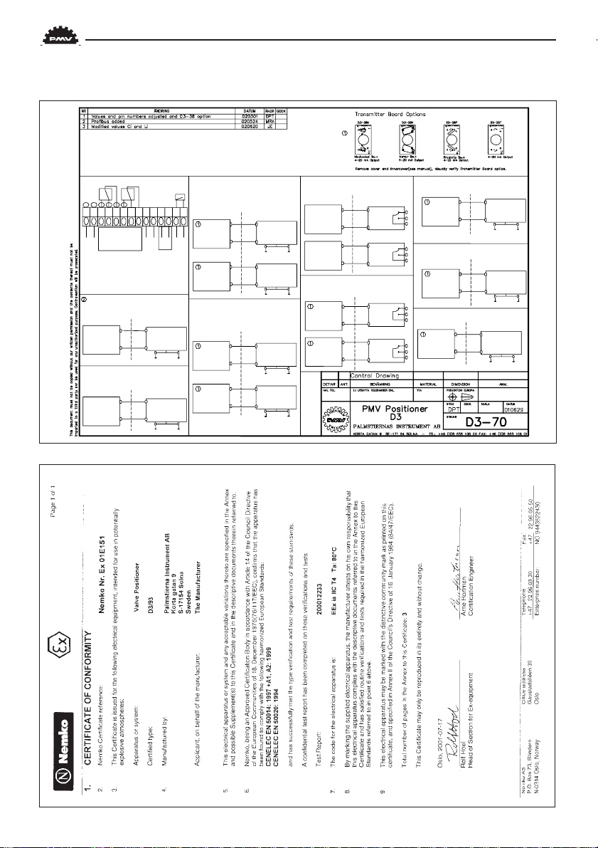
Certificates
53
Page 54
4-20mA input signal
Pin 1;2
AUX input 4-20 mA
Pin 9;10
4-20 mA Output
Pin 11;12
Alarm
Pin 13;14
NAMUR switches
Pin 3;4 : Switch 1
Pin 6;7 : Switch 2
NON HAZARDEOUS AREA
HAZARDEOUS AREA
3
5
Isolator
D3
Ui : 10,6V
Ii : 29,7mA
Pi : 79mW
Ci : 1 nF
Li : 1 µH
NON HAZARDEOUS AREA
HAZARDEOUS AREA
6
8
Isolator
D3
Ui : 10,6V
Ii : 29,7mA
Pi : 79mW
Ci : 1 nF
Li : 1 µH
Mechanical or Proximity switches
Pin 3;5 : Switch 1
Pin 6;8 : Switch 2
NON HAZARDEOUS AREA
HAZARDEOUS AREA
4+
3-
Isolator
D3
Ui : 10,6V
Ii : 29,7mA
Pi : 79mW
Ci : 35 nF
Li : 50 µH
NON HAZARDEOUS AREA
HAZARDEOUS AREA
7+
6-
Isolator
D3
Ui : 10,6V
Ii : 29,7mA
Pi : 79mW
Ci : 35 nF
Li : 50 µH
HART-
connection
Mechanical or Proximity switches
Pin 3;5 : Switch 1
Pin 6;8 :Switch 2
Normally Open
NON HAZARDEOUS AREAHAZARDEOUS AREA
3
5
Safety Barrier
/PA
/PA
NON HAZARDEOUS AREA
HAZARDEOUS AREA
6
8
Safety Barrier
/PA
/PA
NON HAZARDEOUS AREA
HAZARDEOUS AREA
9+
10-
Safety Barrier
/PA
/PA
NON HAZARDEOUS AREAHAZARDEOUS AREA
4
5
Safety Barrier
/PA
/PA
NON HAZARDEOUS AREAHAZARDEOUS AREA
7
8
Safety Barrier
/PA
/PA
Mechanical or Proximity switches
Pin 4;5 : Switch 1
Pin 7;8 : Switch 2
Normally Closed
NON HAZARDEOUS AREAHAZARDEOUS AREA
1+
2-
Safety Barrier
D3
Ui : 28V
Ii : 93mA
Pi : 653mW
Ci : 4 nF
Li : 5 µH
/PA
/PA
NON HAZARDEOUS AREAHAZARDEOUS AREA
13+
14-
Safety Barrier
/PA
/PA
NON HAZARDEOUS AREAHAZARDEOUS AREA
11+
12-
Safety Barrier
/PA
/PA
1. Input signal
2. Input signal
3. Switch 1 NO
4. Switch 1 NC
5. Switch 1 COM
6. Switch 2 NO
7. Switch 2 NC
8. Switch 2 NC
9. AUX 4-20 mA + Input
10. AUX 4-20 mA - Input
11. 4-20 mA +
12. 4-20 mA -
13. Alarm Output +
14. Alarm Output -
7
1
2
3
5
14
8
9
10 11
12
13
4
6
+- +- - -++
Option
Option
D3
Li : 1 µH
Ci : 1 nF
Pi : 315mW
Ii : 45mA
Ui : 28V
D3
Li : 1 µH
Ci : 1 nF
Pi : 315mW
Ii : 45mA
Ui : 28V
D3
Li : 1 µH
Ci : 1 nF
Pi : 315mW
Ii : 45mA
Ui : 28V
D3
Li : 1 µH
Ci : 1 nF
Pi : 315mW
Ii : 45mA
Ui : 28V
D3
Li : 5 µH
Ci : 5,7 nF
Pi : 315mW
Ii : 45mA
Ui : 28V
D3
Li : 5 µH
Ci : 5,7 nF
Pi : 525mW
Ii : 75mA
Ui : 28V
D3
Li : 5 µH
Ci : 5,7 nF
Pi : 315mW
Ii : 45mA
Ui : 28V
Profibus PA input signal
Pin 1;2
NON HAZARDEOUS AREA
HAZARDEOUS AREA
Ui : 15V
Ii : 208mA
Pi : 1,93W
Ci : 4 nF
Li : 5 µH
D3
2
1
Safety Barrier
/PA
/PA
Pin 1: Isrc
Pin 2: Irtn
54
Page 55

55
Page 56

23 24 25 26
4 3 31 17 11 12 13 14 15 16 2 1
9 10 5 7 8
20
27 28 21 22
56
6 19 18
Page 57

Pos P art no. Description
1 D3-SP6 Cover incl.screws
2 D3-SP11 I nternal cover incl.screws
3 P3-SP13 Cover plate incl. screws
4 P5-Sxx Spindle adapter
5 D3-SP1 B lock compl incl. cable, rubber seal, filter-plug
6 D3-SP9 Filter-plug incl. O-ring, filter
7 D3-SP8 Potentiometer compl incl. spring, holder, cable
8 D3-SP8-270 Potentiometer compl incl. spring, holder, cable, 270deg
9D3-SP20 Shaft compl incl. gearwheel, friction clutch
10 D3-SP20-270 Shaft compl.incl. gearwheel, friction clutch, 270deg
11 D3-SP37 Pcb display assy
12 D3-SP35X PCB s (terminal and processor)
13 D3-SP35H PCB s (terminal and processor) HART
14 D3-SP35I PCBs (terminal and processor) intrinsically safe
15 D3-SP35IH PCB s (terminal and processor)intrinsically safe, HA RT
16 D3-SP35P PC Bs (terminal and processor) Profibus
17 P48A Arrow pointer
18 D3-SP/SC R EW K it, bag with screws
19 D3-SP/SE AL K it, bag with O-rings, seals
20 D3-SP42 Cables and PC boards to pneumatic block
21 D3-SP34G Gaugeblock G, complete
22 D3-SP34N Gaugeblock N, complete
23 D3-A S38M Transmitter board, M echanical switches, assy
24 D3-A S38N Transmitter board, Namur sensors, assy
25 D3-A S38P Transmitter board, Proximity switches, assy
26 D3-A S38T Transmitter board 4-20, assy
27 D3-SP46G Dumpvalve valve assy ÓGÓ for single acting
28 D3-SP46N Dumpvalve valve assy ÓNÓ for single acting
30 D3-SP6W C C over incl. screws, Worcester
31 D3-67 Silencer
57
Page 58

12
13
1
3
11
5
9
10
4
58
7 8
19
2
18
17
20
14 15 16 6
Page 59

Pos Part no. Description
1 D3E-SP2 Front cover incl. screw
2 D3E-SP3 Terminal cover incl. screw
3 D3E-SP4 Internal cover incl. screws
4 P5-Sxx Spindle adapter
5 D3-SP1 Block compl. incl. cable, rubber seal, filter-plug
6 D3-SP9 Filter plug incl.O-ring, filter
7 D3E-SP8 Potentiometer compl. incl. spring, holder, cable
8 D3E-SP8-270 Potentiometer compl. incl. spring, holder, cable
9 D3E-SP20 Shaft compl. incl. gearwheel, friction clutch
10 D3E-SP20-270 Shaft compl. incl. gearwheel, friction clutch
11 D3-SP37 Display pcb
12 D3E-SP35X All PCB´s, (processor, mother, terminal)
13 D3E-SP35H All PCB´s, HART, (processor, mother, terminal)
14 D3E-SP40 Terminal PCB
15 D3E-SP/Screw Kit with screws D3E
16 D3E-SP/Seal Kit with O-rings
17 D3E-SP42 Cable for pneumatic block, incl. 2 x PCB
18 D3E-SP46G Dump valve G assy for D3E
19 D3E-SP46N Dump valve NPT assy for D3E
20 D3E-SP18 Adapter complete for dump valv assy
59
Page 60

Palmstiernas Instrument AB
Korta Gatan 9 • 171 54 Solna
Tel: +46 (0)8-555106 00 • Fax: +46 (0)8-555106 01
E-mail: info@pmv.nu • www.pmv.nu
PMW PN 22549/02
 Loading...