

Page 1
PMV D20
Digital Positioner
Installation
Operation
Maintenance
Page 2

2
Contents
1. General information ....................................................................... 3
1.1 Using ............................................................................................ 3
1.2 Terms concerning safety .............................................................. 3
1.3 Protective clothing ........................................................................ 4
1.4 Qualified personnel ...................................................................... 4
1.5 Installation .................................................................................... 4
1.6 Spare parts................................................................................... 4
1.7 Service/repair ............................................................................... 4
1.8 Storage......................................................................................... 5
1.9 Valve and actuator variations ....................................................... 5
2. Unpacking ....................................................................................... 5
3. PMV D20 Overview ......................................................................... 6
4. Specifications ................................................................................. 7
4.1 Technical data .............................................................................. 7
4.2 Mechanical switches .................................................................... 8
4.3 Type sign ...................................................................................... 9
4.4 D20 Model Code ........................................................................ 10
4.5 Control Drawing .......................................................................... 11
4.6 Certificates ................................................................................. 12
5. Principle of operation .................................................................. 16
6. Mounting and installation............................................................ 17
6.1 General ...................................................................................... 17
6.2 Mounting on a linear pneumatic actuator ................................... 17
6.3 Rotary actuators ......................................................................... 19
7. Tubing positioner to actuator ..................................................... 22
8. Wiring and grounding guidelines ............................................... 23
8.1 Grounding screw ........................................................................ 23
8.2 Electromagnetic compability ...................................................... 24
8.3 Compliance voltage.................................................................... 24
9. Operation ...................................................................................... 25
9.1 Operation ................................................................................... 25
9.2 Start up....................................................................................... 25
9.3 Calibration .................................................................................. 25
9.4 Set of Direct or Reverse action .................................................. 26
9.5 Show gain setting ....................................................................... 26
9.6 Change gain setting ................................................................... 27
10. Limit switches & 4 - 20 mA transmitter (Optional) .................. 28
10.1 General .................................................................................... 28
10.2 Model selection ........................................................................ 28
10.3 Principle of operation ............................................................... 28
10.4 Installation ................................................................................ 28
10.5 Calibration of 4 - 20 mA input signal and/or 4 - 20 mA
feedback transmitter................................................................. 29
11. Trouble shooting ........................................................................ 30
11.1 PMV D20 normal operation ...................................................... 30
11.2 PMV D20 error codes ............................................................... 30
11.3 PMV D20 symptoms and solutions .......................................... 31
12. Spare parts ................................................................................. 32
Page 3

1. General information
1.1 Using
The following instructions are designed
to assist in unpacking, installing and
performing maintenance as required on
FLOWSERVE products. Product users
and maintenance personnel should
thoroughly review this bulletin prior to
installing, operating or performing any
maintenance.
1.2 Terms concerning safety
The safety terms DANGER,
WARNING, CAUTION and NOTE
are used in these instructions to
highlight particular dangers and/
or to provide additional information on aspects that may not be
readily apparent.
DANGER: indicates that death,
severe personal injury and/or
substantial property damage will
occur if proper precautions are not
taken.
WARNING:
severe personal injury and/or
substantial property damage can
occur if proper precautions are not
taken.
indicates that death,
3
In most cases FLOWSERVE valves,
actuators and accessories are designed
for specific applications (e.g. with regard
to medium, pressure, temperature). For
this reason they should not be used in
other applications without first contacting
the manufacturer.
NOTE:
indicates and provides
additional technical information,
which may not be very obvious
even to qualified personnel.
Compliance with other, not particularly
emphasised notes, with regard to transport, assembly, operationand
maintenance and with regard to technical
documentation (e.g. in the operating
instruction, product documentation or on
the product itself) is essential, in order
to avoid faults, which in themselves might
directly or indirectly cause severe personal injury or property damage.
CAUTION:
indicates that minor
personal injury and/or property
damage can occur if proper
precautions are not taken.
Page 4

4
1.3 Protective clothing
FLOWSERVE products are often used
in problematic applications (e.g.
extremely high pressures, dangerous,
toxic or corrosive mediums). In particular
valves with bellows seals point to such
applications. When performing service,
inspection or repair operations always
ensure, that the valve and actuator are
depressurised and that the valve has
been cleaned and is free from harmful
substances. In such cases pay particular
attention to personal protection
(protective clothing, gloves, glasses etc.).
1.4 Qualified personnel
Qualified personnel are people who, on
account of their training, experience and
instruction and their knowledge of relevant standards, specifications, accident
prevention regulations and operating
conditions, have been authorised by
those responsible for the safety of the
plant to perform the necessary work and
who can recognise and avoid possible
dangers.
1.5 Installation
DANGER: Before installation
check the order-no, serial-no. and/
or the tag-no. to ensure that the
valve/actuator is correct for the
intended application.
Do not insulate extensions that are
provided for hot or cold services.
Pipelines must be correctly
aligned to ensure that the valve is
not fitted under tension.
Fire protection must be provided
by the user.
1.6 Spare parts
Use only FLOWSERVE original spare
parts. FLOWSERVE cannot accept
responsibility for any damages that occur
from using spare parts or fastening
materials from other manufactures. If
FLOWSERVE products (especially
sealing materials) have been on store for
longer periods check these for corrosion
or deterioration before using these
products. Fire protection for
FLOWSERVE products must be
provided by the end user.
1.7 Service / repair
To avoid possible injury to personnel or
damage to products, safety terms must
be strictly adhered to. Modifying this
product, substituting nonfactory parts, or
using maintenance procedures other
than outlined in this instruction could
drastically affect performance and be
hazardous to personnel and equipment,
and may void existing warranties.
Between actuator and valve there are
moving parts. To avoid injury
FLOWSERVE provides pinch-pointprotection in the form of cover plates,
especially where side-mounted positioners are fitted. If these plates are removed for inspection, service or repair special attention is required. After completing
work the cover plates must be refitted.
Apart from the operating instructions and
the obligatory accident prevention
directives valid in the country of use, all
recognised regulations for safety and
good engineering practices must be
followed.
Page 5

5
WARNING:
Before products are returned to
FLOWSERVE for repair or service
FLOWSERVE must be provided
with a certificate which confirms
that the product has been
decontaminated and is clean.
FLOWSERVE will not accept
deliveries if a certificate has not
been provided (a form can be
obtained from FLOWSERVE).
1.8 Storage
In most cases FLOWSERVE products
are manufactured from stainless steel.
Products not manufactured from
stainless steel are provided with an
epoxy resin coating. This means that
FLOWSERVE products are well
protected from corrosion. Nevertheless
FLOWSERVE products must be stored
adequately in a clean, dry environment.
Plastic caps are fitted to protect the
flange faces to prevent the ingress of foreign materials. These caps should not
be removed until the valve is actually
mounted into the system.
1.9 Valve and actuator
variations
These instructions cannot claim to cover
all details of all possible product
variations, nor in particular can they provide information for every possible
example of installation, operation or
maintenance. This means that the
instructions normally include only the
directions to be followed by qualified personal where the product is being used
for is defined purpose. If there are any
uncertainties in this respect particularly
in the event of missing product-related
information, clarification must be obtained
via the appropriate FLOWSERVE sales
office.
2. Unpacking
Each delivery includes a packing slip.
When unpacking, check all delivered
valves and accessories using this
packing slip.
Report transport damage to the carrier
immediately.
In case of discrepancies, contact your
nearest FLOWSERVE location.
Page 6

6
3.
PMV D20 overview
The PMV D20 is a two-wire loop
powered, 4-20 mA input digital valve
positioner.
The PMV D20 positioner controls
actuators with linear and rotary
mountings.
The PMV D20 is completely powered by
the 4-20 mA input signal. The minimum
input signal required to function is 3,6
mA. As an option the D20 can be
equipped with HART protocol to allow
bidirectional communication.
Since the positioner is insensitive to
supply pressure changes and can
handle supply pressures from 1,5 to 6
barg (22 to 105 psig), a supply regulator
is usually not required; however, in
applications where the supply pressure
is higher than the maximum actuator
pressure rating a supply regulator is
required to lower the pressure to the
actuator’s maximum rating (not to be
confused with operating range). A
coalescing air filter is recommended for
all applications due to the close
tolerances in the positioner.
PMV D20 positioner accessories:
Optional analog feedback system as well
as limit switch unit and a directly
attachable double acting module.
NOTE:
ISA 7.0.01 orIEC 770 (a dew point at
least 10°C/18°F below ambient temperature, particle size below five microns –
one micron recommended – and oil content not to exceed one part per million).
The air supply must conform to
Page 7

7
4. Specifications
4.1 Technical data
Input signal 4-20 mA
Current supply min. 3,6 mA
Current supply Max. 150 mA
Load Standard 400 ohm at 20mA
Load HART 470 ohm at 20mA
Voltage dropStandard 8 VDC at 20mA
Voltage dropHART 9.4 VDC at 20mA
Angle of rotation min 0-40°
Angle of rotation Max 0-90°
Air supply range 1.5 – 6 bar
Out put 0-100% of air supply pressure
Air supply quality Free from oil, dust and moisture IEC 770,
ISA 7.0.01
Air supply effect <0.1%FS for10% pressure change at 6 Bar
Ingress protection IP66 / Nema 4X
Operating humidity 0-100% rh non-condensing
Air connections 1/4” NPT
Cable entry 2 x 1/2” or 2 x M20x 1,5
Te rminals Screw terminals 2,5 mm2 (AWG 14)
Operating Temperature -20 to +85°C-40 to +85°C (optional)
Storage temperature -40 to +85°C
Air delivery capacity 7 Nm3/h @ 6 bar (3 bar diff pressure)
Air delivery capacity Double acting 7 Nm3/h @ 6 bar (3 bar diff pressure)
Air consumption Single acting 0,120 Nm3/h @ 6 bar
Air consumption Double acting 0,120 Nm3/h @ 6 bar
Cv air delivery Single acting 0,12
Cv air delivery Double acting 0,12
Cut off function Close 0.5% Open 99.5%
Linearity <1%
Sensitivity <0.05%
Resolution <0,1%
Repeatability <0.2%
Hysteresis + dead band <0.5%
Temp effect <0.1%/10K
Mounting position effect <0,2%
CE 93/68/EEC, 2004/108/EEC, 2006/95/EEC
Approvals Ex II G Ex ia IIC T4 Ta: 85°C
Certificate nr Nemko 08ATEX1362X
Housing material Die cast Aluminium
Surface treatment Powder coating
Soft goods Nitrile
Weight 1,5 kg
Page 8

8
4.2 Mechanical switches
Type SPDT
Size Sub Sub miniature
Rating 3A, 125 VAC / 2A, 30VDC
Mechanical life >1 x 10⁶ operations
Namur sensors
Type P+F NJ2 V3 N Inductive DIN 19234
Load current <1mA>3mA
Voltage range 5-25 VDC
Hysteresis 3-15% (5% typical)
Temp range -25° to +100° C (-248° to 373° F)
Namur sensors
Type P+F SJ2-N
Normal Voltage 8 VDC
Load current 1mA<I<3mA
Voltage range (5-25 VDC)
Hysteresis (max) 0.2%
Temp range -25° to +100° C (-248° to 373° F)
Namur sensors
Type P+F SJ2-SN
Normal Voltage 8 VDC
Load current 1mA<I<3mA
Voltage range 5-25 VDC
Hysteresis (max) (0.2%)
Temp range -40° to +100° C (-233° to 373° F)
Namur sensors
Type P+F SJ2-S1N
Normal Voltage 8 VDC
Load current 1mA<I<3mA
Voltage range 5-25 VDC
Hysteresis (max) 0.2%
Temp range -25° to +100° C (-248° to 373° F)
Proximity switches
Type SPDT
Rating 10W
Voltage max 200VDC
Current max 500mA
Contact resistance max 0.2 ohm
Page 9

Operating time 1.0 ms
Transmitter
Power supply 12-28 VDC
Output 1-22 mA
Resolution 0.1%
Linearity ±0.5%
Load impedance 600 ohm at (12 VDC and 20mA)
Alarm Output
Supply 3-28 VDC
Output 20mA @ 24 VDC
4.3 Type sign
9
Page 10

10
4.4 D20 Model Code
A = Model no
D20 Digital compact positioner, General purpose, LED status
B = Approval, Certificate
D General purpose version
I Intrinsically safe version ATEX
C = Connections Air, Electrical
M 1/4" NPT air, M20 x 1,5 electrical x 2
N 1/4" NPT air, 1/2" NPT electrical x 2
D = Housing/Surface treatment
U Aluminium/Powder epoxy, black
E = Function
S Single acting
D Double acting, incl gauges (2) Stainless/Brass
F = Mounting options / Spindle
09 Double D type, adaptor spindle
12 Flowtop, D-style+ nut, direct mounting, Kit 30144 include
23 VDI/VDE 3845 rotary, Mounting kit not included
39 IEC 534-6, Flat D type, nut incl. Mounting kit not included
40 VDI/VDE 3847 Linear, Flat D, Mounting kit 30145 included
G = Cover and Indicator
PVA PMV,Black cover, Arrow indicator
PVB PMV, Black cover, No indicator
PVD PMV, Black cover, Dome indicator
H = Temperature/seals
Z Standard -20°C to 85°C (-4°F to 185°F)
Q Low temp -40°C to 85°C (-38°F to 185°F)
I = Input signal/Protocol
4 4-20 mA / none
5 4-20 mA, / HART
J = Feedback option, 4-20 mA transmitter, switches
X No feedback option
T 4-20 mA transmitter only
S Limit switches Mechanical SPDT + 4-20mA
N Namur V3 type sensor, P+F NJ2-V3-N + 4-20mA
P Limit switches Proximity SPDT + 4-20mA
4 Slot type Namur sensor, P+F SJ2-S1N + 4-20mA
5 Slot type Namur sensor, P+F SJ2-SN + 4-20mA
6 Slot type Namur sensor, P+F SJ2-N + 4-20mA
K = Options, Add in electronics
0 Standard diagnostics
L = Accessories
X No accessories
M Gauge block 1/8" G (2 x gauges included)
N Gauge block 1/8" NPT (2 x gauges included)
Example:
A A A B C D - E F F G G G - H I J K L
Page 11
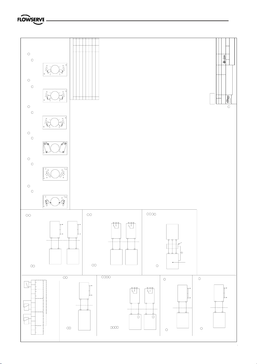
4.5 Control Drawing
UNCLASSIFIED AREA
Isolator
Isolator
4+
Postitioner
Ii : 29,7mA
Pi : 79mW
Ci : 40 nF
Ui : 10,6V
HAZARDEOUS AREA
7+
6-
Positioner
Ui : 10,6V
Pi : 79mW
Ci : 40 nF
Li : 100 µH
Ii : 29,7mA
HAZARDEOUS AREA
3-
Li : 100 µH
Pin 3;4 : Switch 1
Pin 6;7 : Switch 2
UNCLASSIFIED AREA
Pi : 653mW
D2xIxx-xxxxxx-xxTxx
Positioner
Model no: D3Ixx-xxxxxx-
xxTx/Logix 8xx-02-xxxxxx-xxx
-xxT
Pin 9;10
4-20 mA Output
UNCLASSIFIED AREAHAZARDEOUS AREA
Safety Barrier
/PA/PA
10-
Ii : 93mA
Ui : 28V
Li : 11,3 µH
Ci : 16,4 nF
9+
Ci : 5,64 nF
D2xIxx-xxxxx-xxTxx
Positioner
Model no: D3Ixx-xxxxxx-
xxTx/Logix 8xx-02-xxxxxx-xxx
-xxT
Alarm
Pin 11;12
/PA/PA
11+
12-
UNCLASSIFIED AREA
Safety Barrier
Ui : 28V
Pi : 315mW
Ii : 45mA
Li : 11,3 µH
HAZARDEOUS AREA
Pi : 315mW
Positioner
Positioner
Normally Closed
Pin 7;8 : Switch 2
Pin 4;5 : Switch 1
Safety Barrier
3 or 4
5
Pin 3;5 : Switch 1
Pin 6;8 : Switch 2
Normally Open
UNCLASSIFIED AREA
Ui : 28V
Ci : 1 nF
Ii : 45mA
HAZARDEOUS AREA
Pi : 315mW
/PA/PA
/PA/PA
Safety Barrier
6 or 7
8
UNCLASSIFIED AREA
Ui : 28V
Ci : 1 nF
Ii : 45mA
Li : 1 µH
HAZARDEOUS AREA
Li : 1 µH
UNCLASSIFIED AREA
Positioner
Positioner
Pin 7;8 : Switch 2
Pin 4;5 : Switch 1
Normally Closed
Pin 6;8 : Switch 2
Pin 3;5 : Switch 1
Normally Open
Isolator
Isolator
3 or 4
Ui : 10,6V
HAZARDEOUS AREA
5
8
6 or 7
Pi : 79mW
Ci : 1 nF
Li : 1 µH
Ui : 10,6V
Ii : 29,7mA
Ci : 1 nF
Li : 1 µH
Pi : 79mW
HAZARDEOUS AREA
Ii : 29,7mA
UNCLASSIFIED AREA
4
Remote unit output parameter
Po : 0,38W
Positioner
Shielded cable less than 10 metres
HAZARDEOUS AREA
It is only allowed to conne
ct the Pot. unit to the
positioners connectors 3, 4 and 5. The
connection requires a shielded cable less than 10
metres or less than 30 feet.
Pot.
Pin 3;4;5
4
3
55
3
D3Ixx-xxxxxx-xx6x
D2xIxx-xxxxxx-xx6xxD2xIxx-xxxxxx-xx5xxD2xIxx-xxxxxx-xx4xxD2xIxx-xxxxxx-xxNxxD2xIxx-xxxxxx-xxPxxD2xIxx-xxxxxx-xxSxx
Remove cover and innercover(see manual), visually verify Transmitter Board option.
4-20 mA Output
Mechanical Sw.
Transmitter Board Options
3-As81M 3-As81N3-As81P
All components need Saftey Barriers * except the Switches on transmitter board 3-As81N, 3-As81D4,
Explosion Hazard - Do not disconnect equipment unless area is known to be non-hazardous.
Substitution of the following components may impair suitability for Division 2 :
or; read, understand and adhere to the manufacturer's live maintenance procedures.
To prevent ignition of flammable or combustible atmospheres, disconnect power before servicing,
*Only CSA and FM
Substitution of components may impair Intrinsic Safety.
Warnings:
Non-Incendive:
Further requirements for FM:
- Associated apparatus manufacturer's installation drawing must be followed when installing this equipment.
- The Entity Concept allo
ws interconnections of int
rinsically safe apparatus with associated apparatus when the following is true:
Vmax or Ui larger than Voc, Vt or Uo;
Imax or Ii larger than Isc, It or Io
Pmax or Pi larger than Po
Ca larger than Ci + Ccable
La larger than Li + Lcable
- Dust-Tight conduit seal must be when installed in Class II and Class III environments.
- Control equipment connected to Associated Apparatus must not use or generate more than 250 Vrms or Vdc.
- Resistance between Intrinsically Safe Ground must be less than 1,0 Ohm.
- Installation should be in accordance with ANSI/ISA-RP12.06.01 "Installation of Intrinsically Safe Systems for Hazardous (Classified) Locations" and the National
Electric Code (ANSI/NFPA 70).
- The associated apparatus must be FM approved.
- The associated apparatus must be a resistively limited by a single or mult
iple channel FM Approved A
ssociated apparatus having parameters less than those quoted,
and for which the output and the combinations of output is non-ignition capable
for the Class, Divisio
n and Group of use.
Model no:
Logix 8xx-02-xxxxxx-xx1-xxx
4-20 mA Output
Namur Sw.
Proximity Sw.
4-20 mA Output
3-As81D4 3-As81D5 3-As81D6
Slotted Namur Sw.
4-20 mA Output
Slotted Namur Sw.
4-20 mA Output
Slotted Namur Sw.
4-20 mA Output
D3Ixx-xxxxxx-xxSx
Model no:
Logix 8xx-02-xxxxxx-xx2-xxx
D3Ixx-xxxxxx-xxPx
Model no:
Logix 8xx-02-xxxxxx-xx3-xxx
D3Ixx-xxxxxx-xxNx
Model no:
Logix 8xx-02-xxxxxx-xx4-xxx
D3Ixx-xxxxxx-xx4x
Model no:
Logix 8xx-02-xxxxxx-xx5-xxx
D3Ixx-xxxxxx-xx5x
Model no:
Logix 8xx-02-xxxxxx-xx6-xxx
3-As81D5, 3-As81D6, 3-As81P, D3-As38E N, D3-As38E D4, D3-As38E D5, D3-As38E D6 and D3-As38E P.
Pin 2: Irtn
Positioner
/PA
Safety Barrier
/PA
Pin 1;2
1+
2-
HAZARDEOUS AREA
Ui : 28V
Ii : 93mA
Pi : 653mW
Ci : 11,3 nF
Li : 11,3 µH
Pin 1: Isrc
UNCLASSIFIED AREA
REVISIONS
REV. DESCRIPTION DATE MOD. BY
1
"Old" Transmitter board a
ssemblies (D3-AS38E) omitt
ed.
Single acting remote added.
2006-11-14 KBM
2 11.3 was 5 (3x); 11.3 was 4; 16.4 was 4; 11.3 was 5; 5.64 was 5.7
Remote output parameter added.
2007-01-12 KBM
3Model code of Logix 500si added. 2007-11-13 KBM
4Redesigned 2008-03-04 JEE
50 change to x in
"Model no" to allow pressure sens
or option in code. 2008-04-24 MER
6
NAMUR switches, Li: 50
µH changed to
Li: 100
µH; Ci: 35 nF changed to Ci: 40 nF.
2008-04-29 MER
7
Document name changed to D3/D20. Model code for D20 upgraded.
Modelcode for Logix 5XXsi deleted.
2008-11-06 MRn
8. Switch 2 COM
1. Input signal
12. Alarm Output -
11. Alarm Output +
10. 4-20 mA -
9. 4-20 mA +
7. Switch 2 NC
6. Switch 2 NO
5. Switch 1 COM
4. Switch 1 NC
3. Switch 1 NO
2. Input signal
4-20mA input signal
Mechanical or Proximity switches
NAMUR switches
D3Ixx-xxxxxx-xx4x/Logi
x 8xx-02-xxxxxx-xxx-xx4
Model no: D3Ixx-xxxxxx-x4xx/Logix 81x-02-xxxxxx-xxx-xxx
Model no: D3Ixx-xxxxxx-
xxNx/Logix 8xx-02-xxxxxx-xxx
-xx3
1234 5 6789101112
- --
1
2
4-20mA
ALARM
OUTOUT
INPUT
OPTION
NO NC COM NCNO COM
SW1 SW2
(REMOTE)
SIGNAL
D3Ixx-xxxxxx-x5xx/Logi
x 82x-02-xxxxxx-xxx-xxx
D3Ixx-xxxxxx-xx5x/Logi
x 8xx-02-xxxxxx-xxx-xx5
D3Ixx-xxxxxx-xx6x/Logi
x 8xx-02-xxxxxx-xxx-xx6
Model no: D3Ixx-xxxxxx-
xxSx/Logix 8xx-02-xxxxxx-xxx
-xx1
D3Ixx-xxxxxx-xxPx/Logi
x 8xx-02-xxxxxx-xxx-xx2
Model no: D3Ixx-Mxxxxx-xxxx/Logix 8xx-02-xxxxxx-xMx-xxx
D3Ixx-Pxxxxx-xxxx/Logix
8xx-02-xxxxxx-xPx-xxx
to the Notified body
D3Ixx-Rxxxxx-xxxx/Logix
8xx-02-xxxxxx-xRx-xxx
D3Ixx-Qxxxxx-xxxx/Logix
8xx-02-xxxxxx-xQx-xxx
D2xIxx-xxxxxx-x4xxx
D2xIxx-xxxxxx-xxNxx
D2xIxx-xxxxxx-xxSxx
D2xIxx-xxxxxx-x5xxx
D2xIxx-xxxxxx-xx4xx
D2xIxx-xxxxxx-xx6xx
D2xIxx-xxxxxx-xx5xx
D2xIxx-xxxxxx-xxPxx
D3Ixx-xxxxxx-xxPx/Logi
x 8xx-02-xxxxxx-xxx-xx2
D2xIxx-xxxxxx-xxPxx
D2xIxx-xxxxxx-xxSxx
Model no: D3Ixx-xxxxxx-
xxSx/Logix 8xx-02-xxxxxx-xxx
-xx1
Mechanical or Proximity switches
D2xIxR-xxxxxx-xxxxx
No modification permitted without reference
7
Tested according to withstand dielectric strength requirement IEC EN 60079-11 6.3.12
Ingress Protection IP 66, NEMA 4X
Schedule drawing
5
5
5
5
5
5
5
5
5
5
5
5
5
5
5
5
5
5
5
7
Remote unit
5
5
6
7
5
6
7
7
7
7
7
7
7
7
7
7
7
7
7
7
7
7
7
PALMSTIERNA INTERNATIONAL AB
PALMSTIERNA INTERNATIONAL ABPALMSTIERNA INTERNATIONAL AB
PALMSTIERNA INTERNATIONAL AB
DRAWING NO.
DRAWING NO.DRAWING NO.
DRAWING NO.
DRW BY
DRW BYDRW BY
DRW BY APPR. BY
APPR. BYAPPR. BY
APPR. BY SCALE
SCALESCALE
SCALE DATE
DATEDATE
DATE
ANNOTATION
ANNOTATIONANNOTATION
ANNOTATION
DIMENSION
DIMENSIONDIMENSION
DIMENSION
MATERIAL
MATERIALMATERIAL
MATERIAL
DESCRIPTION
DESCRIPTIONDESCRIPTION
DESCRIPTION
PCS
PCSPCS
PCS
PART NO.
PART NO.PART NO.
PART NO.
HOLE TOL.
HOLE TOL.HOLE TOL.
HOLE TOL. UNSPECIFIED TOLERANCES ACCORDING TO:
UNSPECIFIED TOLERANCES ACCORDING TO:UNSPECIFIED TOLERANCES ACCORDING TO:
UNSPECIFIED TOLERANCES ACCORDING TO:
SURFACE
SURFACESURFACE
SURFACE
PROJECTION EUROPA
PROJECTION EUROPAPROJECTION EUROPA
PROJECTION EUROPA
KORTA GATAN 9 SE-171 54
SOLNA SWEDEN - Tel:+46(0)8
555 106 00-Fax:+46(0)8 555 106 01 - www.pmv.nu
KORTA GATAN 9 SE-171 54
SOLNA SWEDEN - Tel:+46(0)8
555 106 00-Fax:+46(0)8 555 106 01 - www.pmv.nuKORTA GATAN 9 SE-171 54
SOLNA SWEDEN - Tel:+46(0)8
555 106 00-Fax:+46(0)8 555 106 01 - www.pmv.nu
KORTA GATAN 9 SE-171 54
SOLNA SWEDEN - Tel:+46(0)8
555 106 00-Fax:+46(0)8 555 106 01 - www.pmv.nu
Control Drawing
Control DrawingControl Drawing
Control Drawing
-
--
-
-
--
-
imparted to
a third party nor be used for any unaut
horized purpose. Contravention will be prosecuted
imparted to
a third party nor be used for any unaut
horized purpose. Contravention will be prosecuted
imparted to
a third party nor be used for any unaut
horized purpose. Contravention will be prosecuted
imparted to
a third party nor be used for any unaut
horized purpose. Contravention will be prosecuted
3-86
3-863-86
3-86
-
--
-
-
--
-
-
--
-
KBM
KBMKBM
KBM
D3/D20
D3/D20D3/D20
D3/D20
PMV Positioner
PMV PositionerPMV Positioner
PMV Positioner
-
--
----
-
This document must not be
copied without our writte
n permission and the contents there of must not be
This document must
not be copied without our writte
n permission and the contents there of must not be
This docume
nt must not be copied without our writte
n permission and the contents there of must not be
This document must not be
copied without our writte
n permission and the contents there of must not be
051208
051208051208
051208
11
Always see www.pmv.nu for latest revision.
Page 12

12
4.6 Certificates
Page 13

131415
Page 14

Page 15

Page 16

16
1 Digital Control
Inner Loop
Piezo Control
Inner Loop
Position feed-
Micro-
Processor
Gain
Local
User
Figure 1.
5. Principle of operation
The PMV D20 positioner is a digital positioner with various options. The positioner consists of three main modules:
1. The microprocessor-based electronic
control module includes direct local user
interface switches
2. The piezo valve-based electropneumatic converter module
3. The infinite resolution valve position
sensor.
The basic positioner operation is best
understood by referring to figure 1. The
complete control circuit is powered by the
two-wire, 4-20 mA command signal. The
analog 4-20 mA command is passed to
the microprocessor, where it is compared
to the measured valve stem position. The
control algorithm in the processor
performs control calculations and
produces an output command to the
piezo valve, which drives the pneumatic
Piezo Valve
Pneumatic
3 Valve
Control
Valve
Stroke
amplifier. The position of the pilot valve
in the pneumatic amplifier is measured
and relayed to the inner loop control
circuit. This two-stage control provides
for more responsive and tighter control
than is possible with a single stage
control algorithm. The pneumatic
amplifier controls the airflow to the
actuator. The change of pressure and
volume of the air in the actuator causes
the valve to stroke. As the valve
approaches the desired position, the
difference between the commanded position and the measured position
becomes smaller and the output to the
piezo is decreased. This, in turn, causes
the pilot valve to close and the resulting
flow to decrease, which slows the
actuator movement as it approaches, the
new commanded position. When the
valve actuator is at the desired position.
the pneumatic amplifier output is held at
zero, which holds the valve in a constant position.
Page 17

6. Mounting and installation
6.1 General
Before starting installation, inspect the digital positioner for any transit damages.
The PMV D20 positioner is installed with a
mounting kit (according to NAMUR
specification) to the left-hand actuator support rod.
Generally, the unit can be installed in any
mounting position. The stroke feed-back
is realized by a follower arm and stem
clamps.
The mounting of rod actuators (according
17
to NAMUR) is described in Figure 3.
For the two mounting possibilities of cast
yoke actuators (according to NAMUR, lEC
534 part 6) refer to Figure 5.
After installation, ensure all screw
connections are tightened correctly and
all moving parts are free from excessive
friction.
Tighten front cover screws to 0.65 Nm to
ensure IP rating.
Figure 2. Dimensional drawing
6.2 Mounting of the PMV D20
positioner on a linear
pneumatic actuator
(NAMUR / IEC 534 part 6)
(See Figure 3)
The mounting of a rod actuator kit
(according to IEC 534 part 6) is described
in an example by using the following
equipment:
Valve: Standard globe valve or
equivalent
Actuator: Single-acting pneumatic
actuator
Positioner: PMV D20 with NAMUR
mounting kit.
Pre-assembly: Valve with actuator (valve
stroke is matched with the actuator
stroke).
Page 18

18
For mounting, proceed as follows:
Mounting the Follower Arm (Figures 3
and 6)
1. Unscrew the lock nut for the follower
arm attachment.
2. Place the follower arm on the shaft at
the back of the positioner and fasten it with
the lock nut. The follower pin should point
back from the positioner.
CAUTION: Maximum torque
0,25 Nm (0,18 ft-lbs).
Mounting the stem clamp bracket and
take-off arm (Figure 3)
1. Attach the stem clamp bracket to the
stem clamp and fasten it with two hexagon socket screws and lock washers.
2. Attach the take off arm to the stem clamp
bracket and fasten it with a hexagon
socket capscrew and a washer. Ensure
the take-off arm slot is centered.
Mounting the positioner (Figure 3)
1. Adjust the actuator to mid-stroke.
2. Pre-assemble the mounting bracket on
the left actuator
leg hand-tight with two U-bolts, nuts and
lockwashers.
3. Attach the positioner to the preassembled mounting bracket and fasten
it with two hexagon head screws and two
lock washers. Check that the follower pin
is inserted in the slot of the take-off arm
and the follower arm is positioned at a right
angle to the outer edge of the positioner.
4. Tighten all screws and nuts.
NOTE: A slight unsymmetrical
mounting increases the linearity
deviation but does not affect the
performance of the device.
Depending on the actuator size
and stroke it may be necessary to
flip the take-off arm (Figure 3) by
180° and attach it to the opposite
side of the stem clamp bracket.
Follower pin adjustment (Figure 4)
The positioner follower pin must be
adjusted to match the valve stroke in the
following manner:
1. Adjust the follower pin (STROKE + 10
mm) as indicated on the follower arm’s
embossed scale (Figure 6).
2. Exhaust the actuator.
3. Loosen the follower pin and shift it along
the follower arm until the control marking
on the feedback gear (Figure 4) is horizontal (points to the center of the feedback potentiometer). Fasten the follower
pin in this position.
4. Adjust the actuator to full stroke and
check the follower pin adjustment the
same way as described in step 3. As the
actuator strokes, the rotation of the feedback gear should be between the inner
control markings. If the length of rotation
is outside the control markings, adjust the
Page 19

Figure 3. Mounting on a Rod Actuator (IEC 534 part 6)
19
follower pin farther out on the feedback
lever to reduce the angle of rotation.
NOTE: Stroke the actuator carefully and
ensure the follower arm does not
interfere with valve parts, actuator or
positioner. Do not adjust the follower pin
too near to the slot end of the take-off
arm.
The minimum lateral distance should be
approximately 5 mm (0,2 inches) to pre-
vent bending of the feed-back
mechanisim.
6.3 Rotary actuators
Mounting the PMV D20 positioner on
a quarter-turn actuator (closed or
open by spring)
The mounting of a pneumatic double-piston part-turn valve actuator (in
accordance with VDI/VDE 3845) is
described as an example by using the
following equipment:
Quarter-turn valve actuator: Rack &
pinion or scotch yoke, closed or open by
spring.
Page 20

20
Rotary actutaors VDI/VDE 3485
(Namur)
Mount bracket 1 to positioner. Secure
with 4 x M6 screws 2.
Fit positioner on actuator and secure
with 4 x screws 3.
Install tubing 4 between actuator and po-
sitioner.
See section 7.
Linear actuator “Flow act” (Direct
mounting, integrated tubing.
Check O-rings, Install bracket 1 to positioner and secure with screws.
Fit pin on valve stem.
Fit lever arm to positioner shaft.
Fit and check O-rings and positioner to
actuator and secure with 2 x screws 2.
No tubing needed, it’s integrated with
actuator, fit plug in positioner out port.
Linear actuator VDI/VDE 3847
(Direct mounting, integrated tubing.
4
1
3
2
1
2
Check O-rings, Install bracket
1 to positioner and secure with 2 x
screws 2.
Fit pin on valve stem.
Fit lever arm to positioner shaft.
Fit and check O-rings and positioner to
actuator and secure with 2 x screws 3.
No tubing needed, it’s integrated with
actuator.
1
2
3
Page 21
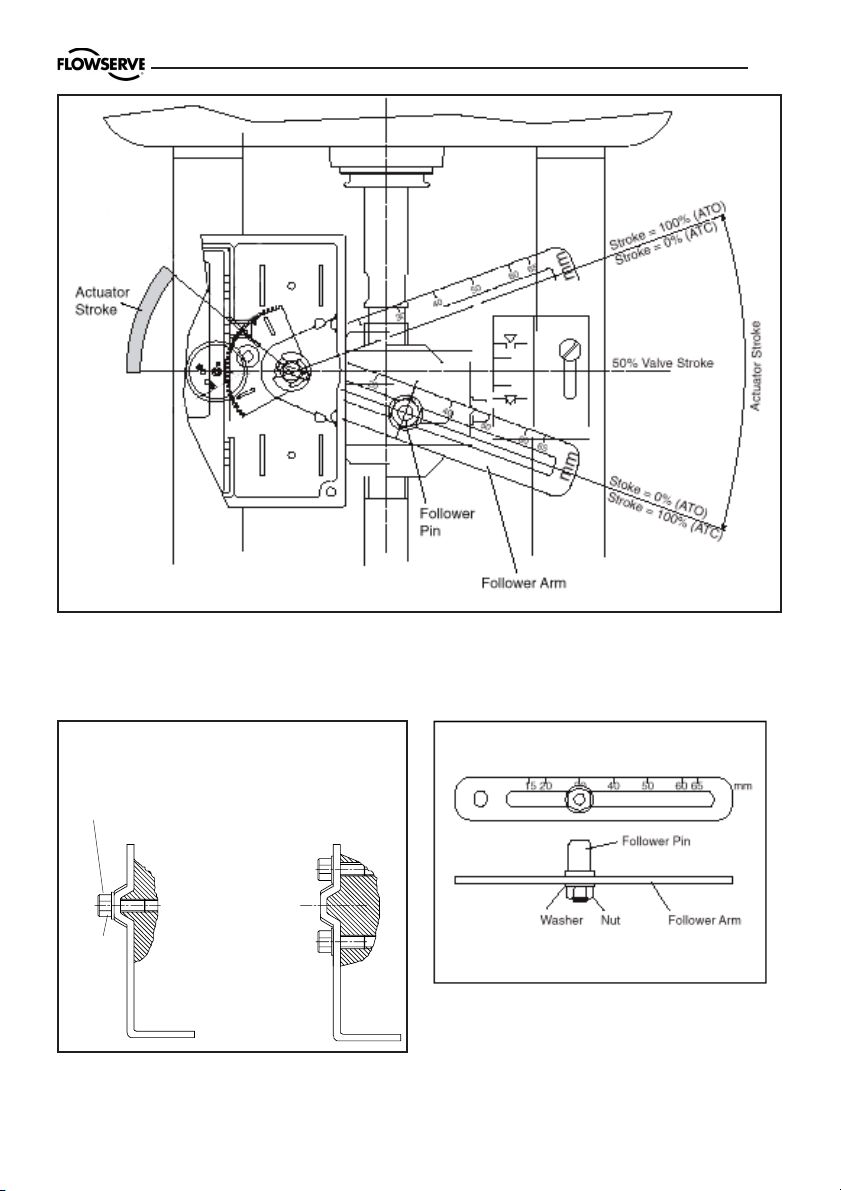
Figure 4. Basic Adjustment for a Linear Pneumatic Actuator
21
Mounting A Mounting B
Hexagon head screw
Lock
washer
Figure 5. Yoke Actuator Mounting
(according to IEC 534 part 6)
Figure 6. Follower Arm (standard)
Page 22

22
2 3
1
Mounting the positioner (Figure 7)
Place the positioner (1) onto the
mounting block (2) of the actuator using
four screws (3) Ensure the coupler fits
on to the shaft of the quarter-turn
connection on the part-turn valve
actuator.
7. Tubing positioner to actuator
Figure 7. Mounting a Part-turn
Valve Actuator in acc. with VDI/
VDE3845
After mounting has been completed,
tube the positioner to the actuator using
the appropriate compression fitting
connectors:
Air connections: 1/4” NPT (standard air
connection).
Auxiliary power: Pressurized air or
permissible gases, free of moisture and
dust in according with IEC 770 or ISA
7.0.01.
Pressure range: 1,5 – 6 bar (30 – 90 psi).
For connecting the air piping, the
following notes should be observed:
1. The positioner passageways are
equipped with filters, which remove medium and coarse size dirt from the
pressurized air. If necessary, they are
easily accessible for cleaning.
2. Supply air should meet IEC 770 or ISA
7.0.01 requirements. A coalescing filter
should be installed in front of the supply
air connection (Figure 8). Now connect
the air supply to the filter, which is
connected to the PMV D20 positioner.
3. With a maximum supply pressure of 6
bar (102 psi) a regulator is not required.
4. With an operating pressure of more
than 6 bar (90 psi), a reducing regulator
is required.
The flow capacity of the regulator must
be larger than the air consumption of the
positioner (7 Nm3 /h @ 6 bar / 4,12 scfm
@ 90 psi).
5. Connect the outlet connector (Figure
8) of the positioner with tubing, independent of the action (direct or reverse).
Page 23

2 - 6 bar
30 - 90 Psi
5 µ
ISO 8573 2.2.2
ISA 7.0.01.-1996 Class 2
8. Wiring and grounding guidelines
Electrical connections: signal cable
with cable passage (1/2” NPT, or M20 x
1,5) to terminals 2 x 2,5 mm.
Input signal: 4 – 20 mA
NOTE: Observe the minimum
requirements of voltage and equivalent
electrical load:
Figure 8. Connections
IN
+ –
4 - 20 mA
23
1 2
8 VDC at 20 mA
The performance is ensured only for a
minimum input current of 3,6 mA.
For wiring, the following notes should be
observed:
NOTE:
The input loop current signal to
the PMV D20 should be in shielded cable.
Shields must be tied to a ground at only
one end of the cable to provide a place
for environmental electrical noise to be
removed from the cable. In general,
shield wire should be connected at the
source. (Figure 8).
Connect the 4-20 mA current source to
terminals +1 and -2, see connection table.
Connection Description
+1 Input +4-20 mA
–2 Input –4-20 mA
Pneumatic output
signal (outlet)
Air supply
8.1 Grounding screw
The grounding screw, located inside the
positioner cover, should be used to provide the unit with an adequate and reliable
earth ground reference. This ground
should be tied to the same ground as the
electrical conduit. Additionally, the
electrical conduit should be earth
grounded at both ends of its run. The
grounded scrrew must not be used to
termingate signal shield wires.
Page 24

24
8.2 Electromagnetic compatibility
The PMV D20 digital positioner has been
designed to operate correctly in
electromagnetic (EM) fields found in
typical industrial environments. Care
should be taken to prevent the positioner from being used in environments with
excessively high EM field strengths
(greater than 10 V/m). Portable EM
devices such as hand-held two-way radios should not be used within 30 cm of
the device.
Ensure proper wiring and shielding
Current
Source
Compliance
Voltage
Figure 9. Compliance voltage
techniques of the control lines, and route
control lines away from electro-magnetic
sources that may cause unwanted noise.
An electromagnetic line filter can be used
to further eliminate noise.
In the event of a severe electrostatic discharge near the positioner, the device
should be inspected to ensure correct
operability. It may be necessary to
recalibrate the PMV D20 positioner to
restore operation.
If Present
R
Barrier
Current
R
Wire
8 VDC
PMV
D20
8.3 Compliance voltage
Output compliance voltage refers to the
voltage limit the current source can provide. A current loop system consists of the
current source, wiring resistance, barrier
resistance (if present), and the PMV D20
impedance.
The PMV D20 requires that the current
loop system allow for a 8.0 - 9.4 VDC
drop across the positioner at maximum
loop current.
CAUTION: Never connect a
voltage source directly across the
positioner terminals. This could
cause permanent circuit board
damage.
In order to determine if the loop will support the PMV D20, perform the following
calculation:
Voltage = Compliance Voltage(@Current
– Current
MAX(Rbarrier
+ R
wire
)
MAX
To support the PMV D20 the calculated
voltage must be greater than 9.4 VDC for
D20 HART and 8 VDC for non-HART.
)
Page 25

25
Example: DCS Compliance Voltage = 19 V
R
= 300Ω
barrier
R
= 25Ω
wire
CURRENT
= 20 mA
MAX
Voltage = 19 V – 0.020 A(300Ω + 25Ω) = 12.5 V
9. Operation
9.1 General
The D20 is operated by the yellow button.
Depending on desired action, press the
button:
- during a number of seconds (Ex: )
or
- a number of times. (Ex: )
x3
All operation steps are indicated by lit or
flashing LED(s).
9.2 Startup
Connect Air supply and a mA-simulator
to the positioner.
5 sec.
This system will support the PMV D20, as
the voltage 12.5 V is greater than the required
8 VDC for non-HART and 9.4 VDC for HART.
ALARM
OPEN/CLOSED
CONTROLLING
Calibration
button
The three LED:s will flash alternately
during calibration.
Warning: During calibration, the
actuator may stroke unexpectedly.
9.3 Calibration
Apply 4 mA current as input signal.
Press the button for 5 sec. (Release the button when the three
LED:s start to flash alternately).
5 sec.
The Calibration procedure will take
between 30 seconds and some minutes
depending on actuator size.
The calibration starts, the
actuator goes go to max. and
min. position and calculates the
control parameters.
After calibration all the three LED:s are
lit for a moment.
A successfull calibration is indicated by
yellow or green LED:
G
Green LED flashes = In service
Yellow LED flashes = In service.
Y
The unit vents in max or min posi-
tion.
An unsuccessfull calibration is indicated
by error codes:
R
D20 does not reach the setpoint.
For other indications, see Error codes,
page 30.
Page 26

26
9.4 Set of Direct or Reverse
action
Note! For safety reason, this operation has to be done max 5 minutes
after calibration. If time has run out,
or if power is disconnected during the
five minutes, perform a new calibration, before changing the
direction.
Run 4 mA. If valve is in right position,
then check the position over the whole
range (8, 12, 16 and 20 mA).
If the direction need to be
changed: press the button 3
x3
times and the direction will
change.
Check operation at 4 – 8 – 12 – 16 and
20 mA
9.5 Show gain setting
If the actuator position is unstable or
selfoscillating after calibration, the gain
can be adjusted.
Gain can be set from A (lowest) to G
(highest). Default is D.
To show the current gain
x4
To indicate the current setting, the LEDs
flashes according to the following:
LEDs show: G (Highest)
LEDs show: F
LEDs show: E
LEDs show: D Default
LEDs show: C
LEDs show: B
LEDs show: A (Lowest)
setting, press the button
four times.
Y R R
Y R Y
Y R G
Y G
Y G G
Y G Y
Y G R
The gain code sequence is repeated 5
times.
Page 27

Button functions:
Press 5 sec = Calibration
Press x3 = Direct/reverse action
Press x4 = Show gain setting
Press x5 - x11 = Change gain
setting
To indicate that a command is
accepted, the three LED:s
light up.
9.6 Change of gain setting
To lower the gain, press the button: 7, 6
or 5 times (5= lowest).
To increase the gain (if actuator is
moving to slow).
x11 G (Highest)
x10 F
x9 E
27
➾
Press the button: 9, 10 or 11 times (11=
highest) to increase the gain.
The LED:s flashes alternately when the
button is pressed. After gain change the
LED:s show the gain code (see 9.3) five
times.
The default value after first calibration is
D .
After this, the gain settings are finished.
x8 D Default
x7 C
x6 B
x5 A (Lowest)
Lower Higher
➾
Page 28
28
10. Limit switches & 4 - 20 mA transmitter (Optional)
Caution!
The installation of electrical
equipment in hazardous areas must
comply with the procedures contained
in the certificates of conformity. Country specific regulations may apply.
Electrical safety is determined only by
the power supply device.
10.1 General
D20 can be equipped with optional plug
in modules for limit switches and/or 4-20
mA feedback transmitter
10.2 Model selection
See D20 model code
10.3 Priciple of operation
The stroke of the actuator/valve is picked
up by the potentiometer inside the D20.
Movement is transferred from actuator
via lever or shaft coupling. Cams/vanes
mounted on the positioner shaft actuate
limit switches 1 and 2. The switching point
can be adjusted on each cam/vane.
The position transmitter converts actual
position into a 4-20mA output signal. This
loop requires an external 12-25 VDC
power supply.
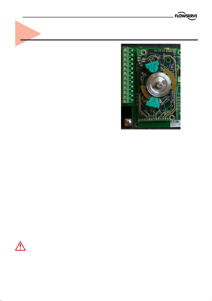
10.4 Installation
Caution! Turn off power and air
supply before starting the installation.
Important!
For D20 installed in hazardous areas,
maintenance and repair must only to be
made by authorized and trained staff.
-Remove cover, indicator if present and
inner plastic cover.
-Check that spacers are installed on the
printed circuit board.
-Carefully install feedback board into its
position on the pins.
-Secure it with two (2) screws.
-Install cam assembly on the shaft, if
feedback card has mechanical micro
switches, be careful to not damage
switch arms.
-Install plastic inner cover.
-Adjust cams/vanes to ensure proper
switching.
-Secure cam/van position by locking
them with two (2) screws.
-Calibrate 4-20 mA transmitter, (see next
page).
-Install cover.
Page 29

29
HARTconnection
12 3 4 5 9
+ – + – + –
Remote unit
10 11 12
Option
1 Input signal + 4-20 mA ,
Hart,
2 Input signal – 4-20 mA ,
Hart
3 Remote unit
4 Remote unit
5 Remote unit
9 4-20 mA + Feedback, 13-28 V DC
10 4-20 mA – Feedback, 13-28 V DC
11 Alarm output +, 8-28 V DC
12 Alarm output –, 8-28 V DC
10.5 D20 Calibration of 4-20 mA input signal and/or 4-20mA
feedback transmitter
• Press and hold button while switching
on power to the D20, keep the button
pressed for 6 sec. The eeprom will now
be erased, and then all three LEDs are
lighted. The LEDs will start to flash
yellow-red. This starts FACTORY MODE!
To calibrate 4-20 mA input signal
• Apply 4.0 mA input signal and then push
the button three (3) times until all LEDs
are lighted. The LEDs will now start flash
yellow-red again.
Apply 20.0 mA input signal and then push
the button three (3) times until all LEDs
are lighted.
To calibrate 4-20 mA transmitter
output signal
Note! If no transmitter board is installed
the LEDs will start flash yellow-yellow and
the unit is ready for continued calibration.
If there is a transmitter board installed
the LEDs will start flash yellow-green.
The feedback transmitter output signal
on pin 9 and 10 will now follow the input
signal instead of the position. Apply 4.0
mA input signal. Measure the output signal and adjust the input signal up/down
until the output signal is 4.0 mA. Push
the button three times until all LEDs are
lighted. The unit will now start to flash
yellow-green again.
The output signal on pin 9 and 10 will
continue to follow the input signal instead
of the position. Apply 20.0 mA input signal. Measure the output signal and adjust
the input signal up/down until the output
signal is 20.0 mA. Push the button three
times until all LEDs are lighted.
The LEDs will start flash yellow-yellow
and the unit is ready for continued
calibration.
Press the button for 5 sec until the LEDs
start alternating, D20 starts to calibrate
stroke.
After calibration the unit will start running
in normal operation.
Page 30

30
11. Trouble shooting
11.1 PMV D20 Normal operation
G
Y
Normal operation.
Valve fully closed or open
”Cut off” enabled.
11.2 PMV D20 error codes
An unsuccessful calibration is indicated by the LED:s. The type of error is shown
by the flash sequence.
Error code Probable Cause Action
R
(Alarm)
Calibration
R G
(No movement)
R Y G
Deviation between set value
and valve position.
No air supply or
shaft do not move.
Pot not calibrated.
Check air supply
Check shaft movement.
Calibrate the pot.
R G R
R R G
R Y R
Y R
Y G
Hallsensor value too low.
Hallsensor span too low.
Hallsensor value too high.
Unit in Factory Mode.
4 - 20 mA feedback installed.
Check hallsensor
connection.
Calibrate 4 - 20 mA
input signal.
Calibrate output.
Page 31

11.3 PMV D20 symptoms and solutions
Failure Probable Cause Corrective action
No LED is flashing. Current source below 3,6 mA . Verify current source
supplies at least 3,6 mA.
Incorrect wiring polarity. Check wiring for correct
polarity.
Valve position reading Stem position sensor mounting Reposition sensor.
is not what is expected. is off 180 degrees.
D20 not calibrated. Calibrate D20.
Tight shutoff MPC (Minimum No action.
position cutoff) is active.
D20 goes in wrong Change direction
direction. (Section 9.4).
31
D20 is oscillating. Decrese gain (Section 9.6).
D20 is responding slow. Increse gain (Section 9.6).
Page 32

32
12. Spare parts
12
9
11
7
8
16
15 19
18
4
17
1
3
5
14
2
21
Page 33

POS PMV P/N Description Remarks
33
1
2
3
3
4
4
5
5
5
5
7
8
9
11
12
14
14
14
14
14
14
14
15
15
15/16
15/16
15/16
15/16
17
18
19
31947
30116
D2-AS5D
D2-AS5N
D2-SP50 STD
D2-SP50 LT
7-SP80 1X
7-SP80-I 1X
7-SP80-H 1H
7-SP80-I-H 1H
30125
D2-SP17
7-SP25B
7-SP25BI
7-SP25
3-As81T
3-As81M
3-As81P
3-As81N
3-As81D4
3-As81D5
3-As81D6
D2-SP40
D2-SP40
D2-SP40
D2-SP40
D2-SP40
S2-SP40
30144
30145
30395
Housing
Lever arm set
Potentionmeter assy. Compl
Shaft D-type Linear, incl nut
Shaft VDI/VDE 3845 Rotary
Air relay assy. Ind. O-rings, screws, standard temp.
Air relay assy. Ind. O-rings, screws, low temp.
Electronics
Electronics, Intrinsically Safe
Electronics, HART
Electronics, HART Intrinsically Safe
Indicator, flat assy. Complete
Indicator, dome style assy. Complete
Front cover, no indicator, black, ind. screws
Front cover, for indicator/dome, black, ind. screws
Inner cover assy.
4-20 mA transmitter only
Mechanical switches assy. comp (incl. cams, screws)
Proximity switches assy. compl.
P+F NJ2-V3-N sensors assy. compl.
P+F SJ2 S1N sensors assy. compl.
P+F SJ2 SN sensors assy. compl.
P+F SJ2N sensors assy.comp.
Gauge block B 1/4" NPT, 1/4" NPT, 1/8" NPT, no gauges
Gauge block C 1/4" NPT, 1/4" NPT, 1/8" G, no gauges
Gauge block B 1/4" NPT, 1/4" NPT, 1/8" NPT, 1 gauge (SS/brass)
Gauge block C 1/4" NPT, 1/4" NPT, 1/8" G, 1 gauge (SS/brass)
Gauge block B 1/4" NPT, 1/4" NPT, 1/8" NPT, 2 gauges (SS/brass)
Gauge block C 1/4" NPT, 1/4" NPT, 1/8" G, 2 gauges (SS/brass)
Flowtop mounting kit incl. O-ring, screws
VDI/VDE 3847 mounting assy. incl. O-rings, screws
Double acting module incl. 2xGauges
N/A
EEx ia
HART
EEx ia, Hart
21
30738
30737
30135
Plug and cable gland kit, black
Seal and O-ring kit
Screw and washer kit
Page 34

Germany
Flowserve
Sperberweg 16
D-41468 Neuss
GERMANY
Tel: +49 (0) 2131 795 74 80
Fax: +49 (0) 2131 795 74 99
E-mail: pmvgermany@flowserve.com
UK
Flowserve
Abex Road
Newbury, Berkshire, RG14 5EY
UK
Tel: +44 (0) 1635 49 400
Fax: +44 (0) 1635 36 034
E-mail: pmvukinfo@flowserve.com
Italy
Flowserve Spa
Via Prealpi, 30
20032 Cormano (Milano)
ITALY
Tel: +39 (0) 2 663 251
Fax: +39 (0) 2 615 18 63
E-mail: infoitaly@flowserve.com
Palmstierna International AB
Korta Gatan 9
SE-171 54 Solna
SWEDEN
Tel: +46 (0) 8 555 106 00
Fax: +46 (0) 8 555 106 01
E-mail: infopmv@flowserve.com
www.pmv.nu
USA, Mexico
PMV-USA
1440 Lake Front Circle, Unit 160
The Woodlands, TX 77380
USA
Tel: +1 281 292 7500
Fax: +1 281 292 7760
E-mail: pmvusa@flowserve.com
Canada
Cancoppas Limited
2595 Dunwin Drive, Unit 2
Mississuga, Ont L5L 3N9
CANADA
Tel: +1 905 569 6246
Fax: +1 905 569 6244
E-mail: controls@cancoppas.com
Asia Pacific Headquarters
Flowserve Pte Ltd.
No. 12 Tuas Avenue 20
REPUBLIC OF SINGAPORE 638824
Tel: +65 (0) 687 98900
Fax: +65 (0) 686 24940
South Africa
Flowserve
Unit 1, 12 Director Road
Spartan Ext. 2
1613 Kempton Park, Gauteng
SOUTH AFRICA
Tel: +27 (0) 11 397 3150
Fax: +27 (0) 11 397 5300
The Netherlands
Fabromatic BV
Rechtzaad 17
4703 RC Roosendaal
THE NETHERLANDS
Tel: +31 (0) 30 6771946
Fax: +27 (0) 30 6772471
E-mail: fcbinfo@flowserve.com
China
Flowserve
Hanwei Building
No. 7 Guanghua Road
Chao Yang District
100004 Beijing
CHINA
Tel: +86 (10) 6561 1900
Fax: +86 (10) 6561 1899
FCD PMENIM0012-01
 Loading...