

Page 1

Worcester Controls
WCAIM2017
(Part 12508)
Model PM15E Electro-Pneumatic Valve Positioner
Installation, Operation and Maintenance Instructions
1. STORAGE INSTRUCTIONS 2
2. INSTALLATION 2
A. Mounting Guide 2
B. Mounting Instructions 3
C. Connections 3
3. OPERATION 4
4. AIR REQUIREMENTS 4
5. FRONT COVER AND INDICATOR COVER 4
6. SPAN AND ZERO ADJUSTMENT 5
7. INDICATOR ADJUSTMENT 5
8. CAM ADJUSTMENT 5
9. REVERSE-ACTING AND SPLIT RANGE 6
10. DAMPERS 6
11. I/P UNIT, PM15E 6
12. REMOVING AND MOUNTING THE I/P UNIT
TO THE POSITIONER UNIT 7
13. MAINTENANCE 8
A. Pilot Valve 8
B. Diaphragm 8
C. Feedback Spring 8
D. Balance Arm 9
E. Lower Arm 9
F. O-Rings 9
G. Filter Plug 9
14. TROUBLESHOOTING 10
15. TECHNICAL DATA 10
Exploded Drawing 11
Spare Part List 12
Page 2

1. STORAGE INSTRUCTIONS
PM15E Positioner Storage and Handling Procedures
PM15E positioners are precision instruments which should be stored
and handled accordingly to avoid problems or damage.
Electro-pneumatic positioners contain electronic components which
can be damaged by exposure to excessive water. Appropriate
precautions should be taken to protect units while in storage.
Warehouse Storage
Stored in original shipping containers, units should be stored in an
environmentally controlled area, i.e., clean, cool (15–26°C, 60–80°F)
and dry, out of direct sunlight or weather exposure.
Field Storage
NOTE: Once the air supply to the positioner is connected and turned
on, internal air bleed will prevent the ingress of moisture and protect
the unit from corrosion. It is recommended that the air supply be left
on at all times.
• If units are installed immediately, turn, and leave on, the air
supply.
• If positioners must be stored outdoors, tighten all covers which
may have loosened in shipment, make sure all open enclosure
points are sealed.
Positioners should be wrapped and sealed air and watertight with
desiccant inside the plastic; units should be securely covered with an
opaque cover and not exposed to direct sunlight, rain or snow.
Units should have all ports sealed and be protected from direct
exposure to weather. For long term storage (>1 month) or overseas
shipment units should be protected with plastic and desiccant.
Potential Damage to Mechanism
When units are stored in hot, humid climates, the daily
heating/cooling cycle will cause air to expand/contract and be drawn
in and out of the positioner housing. Dependent on the local
temperature variations, humidity and dew points and time in storage,
condensation could occur and accumulate inside on the I/P converter
causing erratic operation or failure due to water and corrosion. The
potential for condensation damage is especially high in southern
climates and aggravated if units are exposed to direct sunlight.
For further assistance, please contact your nearest Worcester
distributor.
2. INSTALLATION
Before mounting the positioner, the relationship of the actuator to the
valve must be determined. The actuator can be mounted in-line or
cross-line to the valve. In addition, the actuator can be mounted rightside-up or inverted. If a spring-return actuator is used, the actuator
can be set up to fail with the valve closed or with the valve open. This
gives the end user a total of eight possible set-up configurations.
A. Mounting Guide
The following notes pertain to Positioner Mounting Guide below.
1) “Inverted” actuator position and “Cross-Line” actuator
mounting applies to sizes 10–20 39 Series actuators only. On
sizes 25 and larger, the output shaft is square, which allows
for the coupling to be indexed 90° to the actuator shaft.
Normal actuator position means that the actuator is mounted
“right-side-up”.
2) For spring-return actuators only: “Fail-Open” actuators have a
“9” in position 3 of the ordering code.
3) To change cam to reverse-acting, remove and reinstall upside
down (see Section 9).
4) For double-acting actuators only: Normal hose positions
refers to that described in Section 2.C, Connections.
Flow Control Division
Worcester Controls
2 Model PM15E Electro-Pneumatic Valve Positioner WCAIM2017
Actuator Valve
Actuator Failure Actuator Supply Position
Mounting Mode Position Rotation Positioner Cam Hoses at Min.
(Note 1) (Note 2) (Note 1) to Open Operation (Note 3) Cam Setting Note 4 Signal
In-Line Fail-Close Normal CCW Direct-Acting Direct-Acting 0° (Min. Signal) When Valve is Closed Normal Closed
In-Line Fail-Close Normal CCW Reverse-Acting Reverse-Acting 90° (Max. Signal) When Valve is Closed Reverse Open
Cross-Line Fail-Close Inverted CW Direct-Acting Reverse-Acting 0° (Min. Signal) When Valve is Closed Reverse Closed
Cross-Line Fail-Close Inverted CW Reverse-Acting Direct-Acting 90° (Max. Signal) When Valve is Closed Normal Open
In-Line Fail-Open Inverted CCW Direct-Acting Direct-Acting 90° (Max. Signal) When Valve is Open Normal Closed
In-Line Fail-Open Inverted CCW Reverse-Acting Reverse-Acting 0° (Min. Signal) When Valve is Open Reverse Open
Cross-Line Fail-Open Normal CW Direct-Acting Reverse-Acting 90° (Max. Signal) When Valve is Open Reverse Closed
Cross-Line Fail-Open Normal CW Reverse-Acting Direct-Acting 0° (Min. Signal) When Valve is Open Normal Open
Actuator
Positioner
Page 3
B. Mounting Instructions for a Direct-Acting PM15E to a Spring-
Return or Double-Acting 39 Actuator:
The most common installation configuration is with the actuator
mounted in-line, direct-acting, and with spring return set for failclosed. Direct-acting means that as the signal increases, the valve
travels in the open direction.
1) Close the valve/actuator assembly if it is not already closed
(fully CW).
2) Remove the position indicator, if any, from the actuator shaft.
3) Attach the mounting bracket to the top of the actuator such
that the indicating scale is upright and on the same side of the
actuator as the actuator nameplate. Use four (4) screws and
lockwashers supplied with mounting kit.
4) Place coupling on actuator shaft. DO NOT tighten set screws
at this time.
5) Install the indicating arm and locknut on the coupling such
that the end of the arm points downward.
6) Place the positioner on the bracket so that the actuator
nameplate and the side of the positioner with the zero
adjustment are on the same side. Positioner is mounted to
bracket using mounting adapter and screws (5). See
illustration below.
7) Align the mounting holes and then use the two (2)
5
/
16-18
socket head cap screws, lockwashers, hex nuts, and rubber
washers (between bracket and positioner) supplied with the
mounting kit to fasten the positioner to the bracket.
8) Tighten the set screw at the upper end of the coupling to the
positioner shaft (seat the set screw in the positioner shaft
groove). The other two set screws will be tightened after the
actuator is cycled 90°. Proper alignment of the positioner
spindle to the actuator shaft is very important since improper
alignment can cause excessive wear and friction to the
positioner.
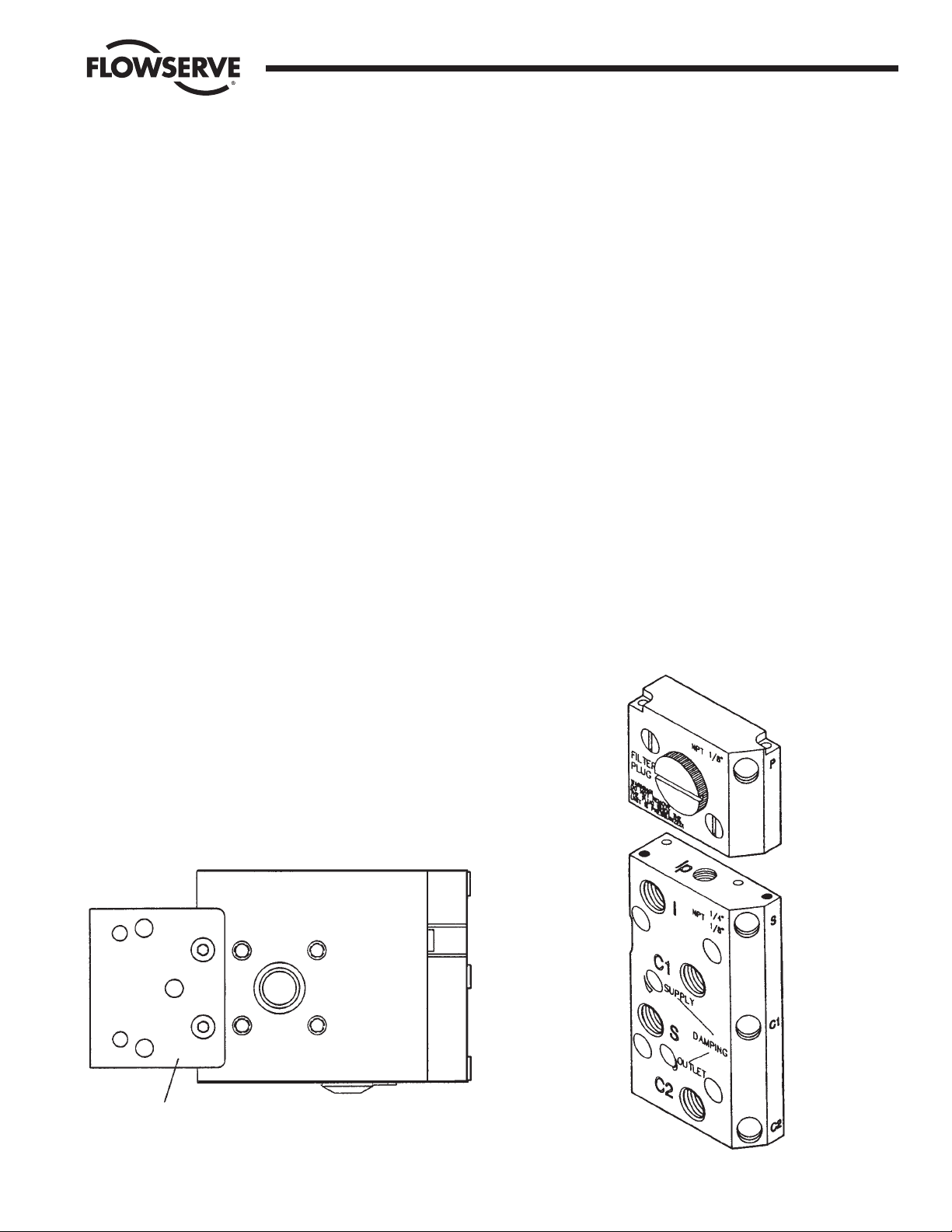
C. Connections
Air connections are tapped for
1
/
4" NPT male connectors and are
clearly marked. Gauge ports Ip, P, S, C1, C2 are
1
/
8" NPT. We
recommend use of tape, Loctite®577 or similar for sealing.
Electrical connection on I/P unit accepts
1
/
2" NPT cable gland.
Port I Not used and will be plugged.
Port S Supply air, maximum 0.9 MPa (125 psi),
minimum 0.15 MPa (21 psi) for PM15E.
Port C1, C2 Actuator connections (0.2-0.9 MPa).
C2 opening port.
OUT Exhaust air port. Do Not Block!
Port Ip Used as air passage to I/P unit.
Port IE Input electric signal (4-20 mA)
(on the I/P unit).
Port P Gauge port for I/P unit output pressure
(on the I/P unit).
Ports P, S, C1 and C2 are sealed with plugs. To install gauges,
unscrew plugs and replace with gauges. Gauges for these ports
are supplied by customer.
We recommend use of tape, Loctite
®
577 or similar for sealing.
Port OUT is for venting the unit. All air from the positioner,
actuator and I/P unit is vented to atmosphere through this port.
Do not block this port. If port is covered or plugged, remove
Flow Control Division
Worcester Controls
WCAIM2017 Model PM15E Electro-Pneumatic Valve Positioner 3
5
Page 4
before pressurizing. A high flow silencer or an exhaust pipe can
be connected to this port to prevent foreign objects from entering
and blocking the unit’s exhaust.
When using gases other than air for supply, please contact
Worcester.
Connect the air supply line to port S.
For double-acting operation, connect the right-hand and the lefthand ports of the actuator end cap (right-hand end cap when
facing actuator nameplate) to ports C2 and C1 respectively.
For single-acting operation, plug port C1 for increasing signal to
open or close. Plug C2 for decreasing (reverse) signal to close.
The 4-20 mA signal wires will be connected to the terminal block
by passing the wires through port I
E
. Be certain that you observe
proper polarity when making the connections. Remove cover (62)
for access.
3. OPERATION
The PM15E operates on a force balance principal. Force is originated
by the signal pressure transmitted through a diaphragm onto the
balance arm. The opposing force is achieved through the feedback
spring and is proportional to the position of the lower arm. The lower
arm position is determined by the position of the cam which is
secured to the spindle and connected to the actuator shaft, thus
providing the feedback from the actuator/valve. When these two
forces are equal, the balance arm and the spool in the pilot valve are
in neutral position—the complete unit is in a balanced position. Air is
supplied to the pilot valve through port S, and controls the air flow
through ports C1 and C2.
Assume an equilibrium position.
An increased control pressure will deflect the diaphragm (1) down,
compressing the feedback spring (3). The balance arm (2) moves the
spool (7) in the pilot valve (8) furnishing supply air to the actuator,
while at the same time air is exhausted from actuator and is vented to
atmosphere through the pilot valve and the OUT port.
With the increased supply air, the actuator rotates (or moves linearly),
moving the positioner spindle (6). The spindle and cam (5) rotate,
forcing the lower arm (4) upwards, compressing the feedback spring
(3). This motion will continue until two forces are equal and the unit is
an equilibrium position.
4. AIR REQUIREMENTS
Maximum supply pressure is 0.9 MPa (125 psi).
Supply air shall be clean, dry and free from oil, water, moisture,
foreign parts and debris.
The air shall be freeze-dried or similar to a dew point of at least 10°C
(18°F) below lowest expected ambient temperature.
A < 40 micron filter/regulator is recommended to be installed as close
to PM15E as possible to ensure proper supply air quality.
5. FRONT COVER
AND INDICATOR COVER
The front cover of the PM15E is secured to the pneumatic unit with
four captured screws and sealed with an O-ring (1). The O-ring can be
looped over notches (2) in the front cover to allow for drainage. There
are eight locations on the front cover where the O-ring can be looped.
This O-ring system is common to the pneumatic unit and I/P unit in
the PM15E. This unique sealing system allows for complete sealing or
draining of the units by changing the position of the O-ring.
The indicator cover (3) is O-ring sealed and secured by a bayonet
coupling. The indicator cover is also used to secure the identification
cover (4).
To remove the indicator cover, turn it slightly counterclockwise until it
loosens. Identification cover and O-ring (5) are now removable. When
installing indicator cover and identification cover, make sure that the
O-ring is properly engaged.
Flow Control Division
Worcester Controls
4 Model PM15E Electro-Pneumatic Valve Positioner WCAIM2017
8
7
1
2
4
6
5
3
Page 5

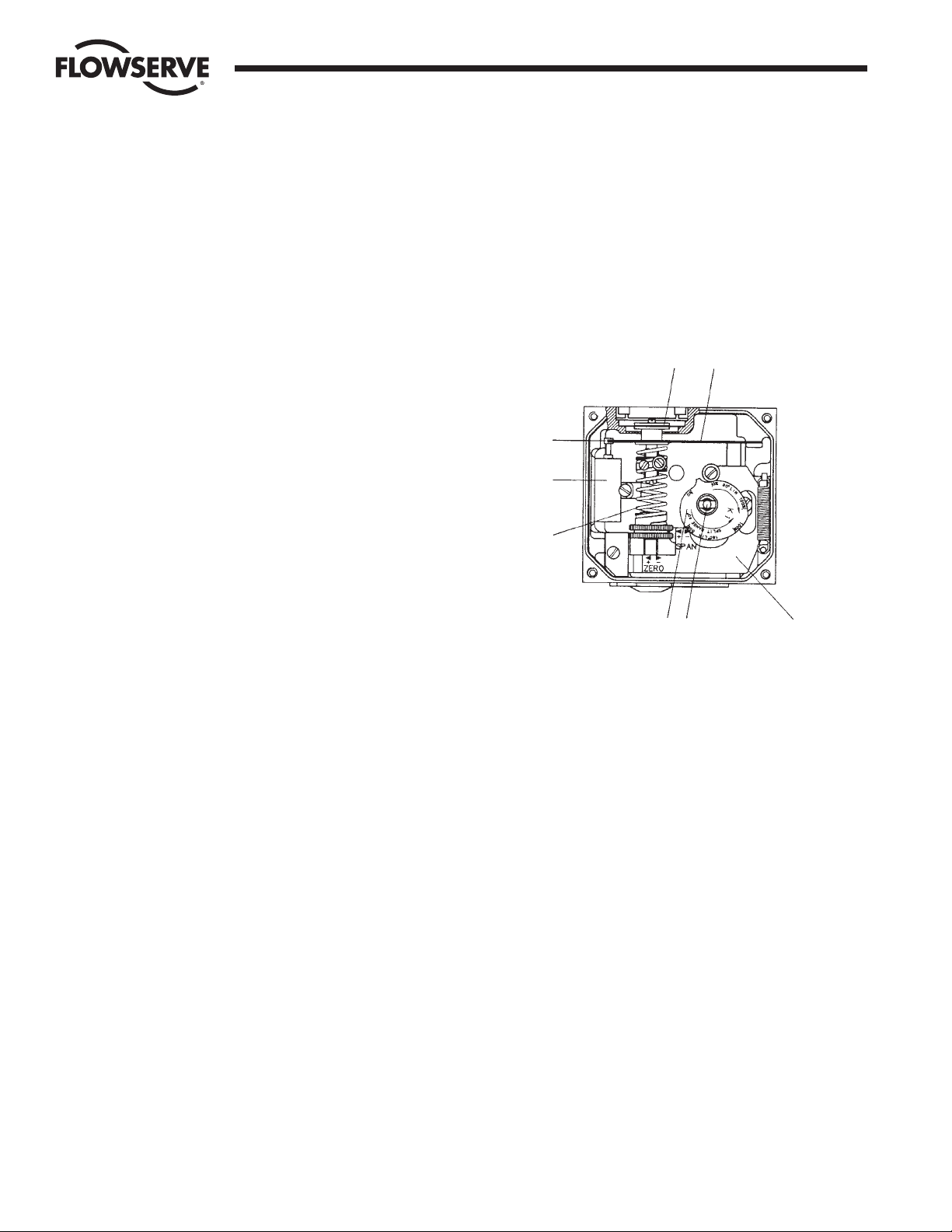
6. SPAN AND ZERO ADJUSTMENT
Span is adjusted with the brass-colored (upper) thumb wheel (1)
located on the feedback spring.
To adjust the span, always return to minimum input signal first, then
loosen the locking screw (2) and turn thumb wheel (1). Tighten screw
(2) when span is set. Do not allow the top of the spring to contact the
spring guide (3).
Always check zero after adjusting span.
Zero is adjusted by turning the silver (lower) thumb wheel (4) located
on the lower arm (5), or externally with a screwdriver (7) through the
zero adjustment opening. Remember to install cover (6) to ensure the
unit seals.
7. INDICATOR ADJUSTMENT
To adjust the indicator, take off front cover and pull the indicator
upwards until it comes off the Allen screw.
Before installing the indicator make sure that the Allen screw is
tightened. Press the indicator on the screw and adjust it by rotating
clockwise to desired position.
8. CAM ADJUSTMENT
With the cover and indicator removed, loosen the screw (1) and turn
the cam locking nut (2) counterclockwise until the cam loosens.
Adjust the cam (3) as desired, making sure that the ball bearing (4) is
always riding on an active lobe on the cam. To secure the cam, make
sure that screw (1) is backed out from the locking nut (2), then fingertighten the locking nut and tighten screw (1). Install and adjust the
indicator and reinstall cover.
Flow Control Division
Worcester Controls
WCAIM2017 Model PM15E Electro-Pneumatic Valve Positioner 5
1
2
1
3
1
5
4
3
2
4
5
3
4
1-2 mm (
1
/
16
")
1
2
6
7
Correct
Incorrect
Page 6

9. REVERSE-ACTING
AND SPLIT-RANGE
Reverse-Acting
For reverse-action operation, invert cam. Also reverse connections C1
and C2. For single-acting actuators, move actuator connection from
C2 to C1 and plug C1.
Split-Range
For split-range, reposition the cam, noting the markings on the cam:
for 4-12 mA, use initial 50% zone; for 12-20 mA, use 51–100% zone.
10. DAMPERS
The standard built-in dampers (5) located on the connecting block
provide a simple means of adjusting the actuator travel speed.
For maximum actuator travel speed, dampers shall be adjusted to
minimum damping position.
Double-Acting Actuators – Adjust only OUTLET damper; set SUPPLY
damper in minimum damping position.
Single-Acting Actuators – Adjust both dampers for desired operation.
11. I/P UNIT, PM15E
I/P unit is mounted directly on top of the positioner unit. No external
air supply is needed since the I/P unit is supplied with air from the
positioner unit.
The I/P unit is equipped with a built-in 30 micron filter (Figure 4).
CAUTION: Do not operate the unit without filter and filter plug
installed. Do not unscrew filter plug when the positioner is
pressurized.
Span and zero for the I/P converter is factory set and should not
require adjustment.
I/P Calibration
Check I/P output by connecting gauge to port P.
• Adjust Zero on screw 2.
• Adjust Span on screw 1.
Flow Control Division
Worcester Controls
6 Model PM15E Electro-Pneumatic Valve Positioner WCAIM2017
5
1
Figure 1
Figure 2
Figure 3
Figure 4
2
Page 7

12. REMOVING AND MOUNTING
THE I/P UNIT TO THE
POSITIONER UNIT
Switch off supply air and disconnect input signal (port I). Loosen
screws (3) and remove connection block (1), the gauge or plug from
port Ip, the fitting from port I and existing gasket (4). Carefully install
gasket (6) supplied together with I/P unit. When correct, installed
port I will be blocked by the gasket.
Make sure that relief valve spring (5) is installed properly. Install the
connection block (1) to the positioner unit (2).
Remove cover on I/P unit.
Install the I/P unit to the top of the positioner unit, making sure that
the four O-rings are present and properly seated. Tighten the unit with
the three screws (see Figure 1 and Figure 2, page 6).
Connect input signal cable to port I
E
and tighten the cable gland (see
Figure 5 on Page 6). Adjust the O-ring on the I/P unit housing to
desired position—sealed or drained (see Figure 3 on page 6 or
Section 5 on page 4).
A gauge indicating output signal from the I/P converter can be
installed in port P. Make sure that the filter plug is tightened before
supply air is switched on (Figure 4 on page 6).
Flow Control Division
Worcester Controls
WCAIM2017 Model PM15E Electro-Pneumatic Valve Positioner 7
1
3
6
5
4
2
Page 8

13. MAINTENANCE
A. Pilot Valve
To remove the pilot valve for cleaning or inspection, remove the
screw (1) and carefully lift out the complete assembly (2). Gently
remove the spool (3) from the block and clean the parts, using
methylate cleaner or similar. Blow parts dry with compressed air.
Should the parts show signs of wear, a new assembly is
recommended. Mixing spool valves and valve bodies may result in
very high bleed rates and poor performance. Check the O-rings,
then secure and install the pilot valve assembly to the positioner
unit and secure it with the screw (1). Make sure that the leaf
spring (4) on the balance arm (5) is properly fitted in the groove
on spool (6). Check again to ensure smooth operation of the
assembly.
To maintain original factory performance specifications, use only
spool valve assemblies supplied by Flowserve.
B. Diaphragm
The I/P unit must be removed to access the diaphragm. (See
previous section.) Then loosen screws (1) and remove the
diaphragm cover (2). Loosen screw (3); diaphragm (4) and
washers (5) can be removed.
When installing the diaphragm, make sure to place one washer on
each side of the diaphragm. Make sure that the raised circle on
the washers is facing the diaphragm.
Install the screw (3) and tighten.
Check the O-ring on the diaphragm cover (2), then install and
secure the cover with screws (1).
C. Feedback Spring
Once the front cover and indicator are removed, the feedback
spring can be easily accessed.
Hold the spring (1) from the top, pull down and out.
When installing, hold the assembly at the top, guide the lower part
to position on the zero screw, then press down until it fits easily
under the balance arm (2). Make sure that the assembly is aligned
properly against the lower arm and the notch is engaged in the tab
on the balance arm (2).
Flow Control Division
Worcester Controls
8 Model PM15E Electro-Pneumatic Valve Positioner WCAIM2017
1
2
3
6
5
4
2
1
5
34
2
1
Page 9

D. Balance Arm
The balance arm can only be removed after I/P unit, diaphragm
and feedback spring have been removed. (See previous sections.)
Loosen the screws (3) and the balance arm can be removed.
When installing the balance arm make sure that the leaf spring (4)
on the underside of the balance arm (5) is properly engaged into
the groove (6) of the spool in the pilot valve.
Tighten the two screws (3) holding the balance arm to the
positioner.
E. Lower Arm
Once the front cover is removed, the lower arm can be easily
accessed. Remove the indicator, feedback spring and the cam.
Loosen screw (2) and remove twist stop (1). Remove screw (3),
lower arm (4), rod (5) and spring (6).
Check rod and lower arm for wear; replace if necessary. Clean the
rod and install it in the lower arm. The lower arm should move
easily and smoothly.
Install the lower arm and rod assembly into the positioner
housing, making sure that the spring (6) is attached properly to
the lower arm and positioner housing.
Secure the lower arm and rod assembly with the screw (3). Check
again that the lower arm moves smoothly.
Apply a small amount of grease on the small tongue on the lower
arm, then install and secure the twist stop.
Install cam, feedback spring, indicator and front cover.
F. O-Rings
With time and use, O-rings can become brittle. This can cause
poor operation and even failure of the positioner.
Always check O-rings when performing any work on the
positioner and replace bad O-rings.
A thin layer of silicon grease applied on the Buna N (Black)
O-rings prolongs their life. On Q (Red Silicon) O-rings, use a nonsilicon based grease.
G. Filter Plug
CAUTION: Do not operate the unit without filter and filter plug
installed. Do not attempt to unscrew filter plug while positioner
is pressurized.
The PM15E is equipped with a built-in secondary filter located on
the side of the I/P unit.
For replacement or inspection, make sure that positioner unit is
not pressurized, then unscrew filter plug (1). Remove filter (3)
and install a new one into the filter plug. Check condition of O-ring
(2) and filter compartment. If moisture is found, check upstream
filters/oil-water separators. Moisture can cause I/P failure.
Reinstall filter plug.
Flow Control Division
Worcester Controls
WCAIM2017 Model PM15E Electro-Pneumatic Valve Positioner 9
3
4
5
6
2
15
6
3
4
1
2
3
Page 10

14. TROUBLESHOOTING
NOTE: All PM15E positioners are serialized and date coded. Please
note date, and provide the serial number when contacting the factory
for troubleshooting or service.
Signal change results in actuator running to end positions:
_____ Check coupling between positioner and actuator.
_____ Check cam position and locking screw.
_____ Check input signal.
Signal change has no effect on the actuator position:
_____ Check indicator and screw.
_____ Check air supply to positioner and tubing to the actuator.
_____ Check input signal to positioner.
_____ Check diaphragm for damage or leakage.
_____ Check pilot valve function.
_____ Check cam for correct setting.
_____ Check I/P output.
Inaccurate positioning:
_____ Dirty or worn pilot valve.
_____ Defective or leaking diaphragm.
_____ Input signal fluctuates.
_____ Incorrect sizing of actuator.
_____ Valve/actuator “stiction”.
_____ High valve/actuator breakaway torque.
_____ Loose cam.
15. TECHNICAL DATA
Input Signal 4-20 mA
Linearity < 0.75%*
Hysteresis < 1%*
Repeatability < 0.5%*
80% Load (Supply Pressure 87 psi) 1,000 (kPa/kPa) (psi/psi)
50% Load (Supply Pressure 87 psi) 1,250 (kPa/kPa) (psi/psi)
Air Consumption at Supply Pressure ± 20%
0.2 MPa/29 psi 6.1 nl/min 0.22 SCFM
0.4 MPa/58 psi 13.6 nl/min 0.48 SCFM
0.6 MPa/87 psi 22 nl/min 0.78 SCFM
0.8 MPa/116 psi 30.5 nl/min 1.08 SCFM
1 MPa/145 psi 39 nl/min 1.38 SCFM
Air Delivery at Supply Pressure ± 20%
0.2 MPa/29 psi 200 nl/min 6.9 SCFM
0.4 MPa/58 psi 370 nl/min 12.8 SCFM
0.6 MPa/87 psi 540 nl/min 18.8 SCFM
0.8 MPa/116 psi 710 nl/min 24.7 SCFM
1 MPa/145 psi 880 nl/min 30.6 SCFM
Supply Pressure 0.15-0.9 MPa/21.8-125 psi
Temperature Range -20°C to +85°C
(-4°F to 185°F)
Connector Threads
1
/
4" NPT
Gauge Threads
1
/
8" NPT
Weight Std. 1.5 kg/3.4 lbs.
Weight with Gauges 1.8 kg/3.9 lbs.
Ingress Protection IP 66/NEMA Type 4
*Percent of full scale.
Flow Control Division
Worcester Controls
10 Model PM15E Electro-Pneumatic Valve Positioner WCAIM2017
Page 11

Flow Control Division
Worcester Controls
WCAIM2017 Model PM15E Electro-Pneumatic Valve Positioner 11
Page 12

Pos Part No. Qty Description
1 1 Housing
2 P5-2 1 Front Cover Including O-Ring
3 P5-AS3N 1 Connecting Block NPT
1
/
4"
Assembly
4 P5-4 1 Relief Valve Spring
6 P5-6EP 1 Gasket for EP5
7 P5-7 1 Diaphragm Cover Including
O-Ring
8 P5-8 1 Diaphragm
9 P5-9 2 Diaphragm Washer
10 P5-10 1 Balance Arm
13 P5-AS13/315 1 Feedback Spring
3-15 PSI Assembly
18 P5-18 1 Lower Arm Assembly
19 P5-19 1 Rod
20 P5-20 1 Spring
21 P5-21A 1 Indicator Arrow
22 P5-22T 1 Indicator Cover Transparent
Including O-Ring
24 P5-24 1 Twist Stop
25 P5-25 1 Pilot Valve Including O-Rings
26 P5-26 1 Shaft Including O-Rings,
Screw
27 P5-27 1 Cam, Locking Nut Including
Screw
29 P5-29 1 Zero Cover
30 P5-30 1 Cover
31 P5-31 1 Mounting Adapter Including
Screws
32 P5-32 1 Ball Bearing
Pos Part No. Qty Description
35 P5-xx/xx 1 Identification Cover
36 12047N 4 Plug NPT
1
/
8"
37 P5-K1 1 Cam
38–45 P5-Screws 1 Screw Set P5/EP5
75–80
46–53 P5-Seal NBR 1 O-Ring Set P5/EP5
81–83, 6, 67, 70 Nitrile, NBR
46–53 P5-Seal Q 1 O-Ring Set P5/EP5
81, 83, 6, 67, 70 Silicone Q
54 P5-S3 1 Spindle Adaptor
I/P Unit Part List
61 1 I/P Box
62 E5-2 1 I/P Cover Including Screws
63 E5-AS3N 1 I/P Nose NPT
1
/
4" Assembly
64 P5-4 1 Relief Valve Spring
65 P5-5 1 Filter Plug Including Filter 66,
O-ring, 81
66 E5-6 1 Filters (5 per Package)
67 E5-7 1 Gasket I/P
71 E5-STD 1 I/P Converter
73 E5 N-AS 11 1 Mounting Bracket Round I/P
Including Screws, O-Rings,
I/P Nose
E5 G-AS 11
74 FU-STD 1 Enclosure Including I/P
Converter Std.
74 E5-EX/US 1 Enclosure Including I/P
Converter, Explosion-Proof
FM, CSA
Spare Part List
Flow Control Division
Worcester Controls
© 2003 Flowserve Corporation, Irving, Texas, USA. Flowserve and Worcester Controls are registered trademarks of Flowserve Corporation. WCAIM2017 10/03 Printed in USA
For more information about Flowserve Corporation, contact www.flowserve.com or call USA 1-800-225-6989.
FLOWSERVE CORPORATION
FLOW CONTROL DIVISION
1978 Foreman Drive
Cookeville, Tennessee 38501 USA
Phone: 931 432 4021
Facsimile: 931 432 3105
www.flowserve.com
Flowserve Corporation has established industry leadership in the design and manufacture of its products. When properly selected, this Flowserve product is designed to perform its intended function
safely during its useful life. However, the purchaser or user of Flowserve products should be aware that Flowserve products might be used in numerous applications under a wide variety of industrial
service conditions. Although Flowserve can (and often does) provide general guidelines, it cannot provide specific data and warnings for all possible applications. The purchaser/user must therefore
assume the ultimate responsibility for the proper sizing and selection, installation, operation, and maintenance of Flowserve products. The purchaser/user should read and understand the Installation
Operation Maintenance (IOM) instructions included with the product, and train its employees and contractors in the safe use of Flowserve products in connection with the specific application.
While the information and specifications contained in this literature are believed to be accurate, they are supplied for informative purposes only and should not be considered certified or as a guarantee of
satisfactory results by reliance thereon. Nothing contained herein is to be construed as a warranty or guarantee, express or implied, regarding any matter with respect to this product. Because Flowserve
is continually improving and upgrading its product design, the specifications, dimensions and information contained herein are subject to change without notice. Should any question arise concerning
these provisions, the purchaser/user should contact Flowserve Corporation at any one of its worldwide operations or offices.
 Loading...