

Page 1

Worcester Controls
CONTENTS
Page
1. STORAGE INSTRUCTIONS........................................................................................................................................................................2
2. INSTALLATION..........................................................................................................................................................................................2
A. Mounting Guide....................................................................................................................................................................................2
B. Mounting Instructions ..........................................................................................................................................................................3
C. Connections..........................................................................................................................................................................................4
3. OPERATION ..............................................................................................................................................................................................4
4. AIR REQUIREMENTS................................................................................................................................................................................4
5. SPAN AND ZERO ADJUSTMENT...............................................................................................................................................................5
6. CAM ADJUSTMENT ..................................................................................................................................................................................6
7. REVERSE-ACTING AND SPLIT-RANGE.....................................................................................................................................................6
8. MAINTENANCE .........................................................................................................................................................................................7
A. Pilot Valve.............................................................................................................................................................................................7
B. Diaphragm............................................................................................................................................................................................7
C. Feedback Spring...................................................................................................................................................................................8
D. Balance Arm.........................................................................................................................................................................................8
E. Lower Arm............................................................................................................................................................................................9
F. O-Rings ................................................................................................................................................................................................9
9. TROUBLESHOOTING ..............................................................................................................................................................................10
10. TECHNICAL DATA ...................................................................................................................................................................................10
11. SPARE PART LIST ..................................................................................................................................................................................11
12. EXPLODED DRAWING ............................................................................................................................................................................11
WCAIM2016
(Part 12506)
PM15 Pneumatic Valve Positioner
Installation, Operation and Maintenance Instructions
Page 2
1. STORAGE INSTRUCTIONS
PM15 Positioner Storage and Handling Procedures
PM15 positioners are precision instruments which should be stored
and handled accordingly to avoid problems or damage.
Warehouse Storage
Stored in original shipping containers, units should be stored in an
environmentally controlled area, i.e., clean, cool (15–26°C, 60–80°F)
and dry, out of direct sunlight or weather exposure.
Field Storage
NOTE: Once the air supply to the positioner is connected and turned on,
internal air bleed will prevent the ingress of moisture and protect the unit
from corrosion. It is recommended that the air supply be left on at all
times.
• If units are installed immediately, turn, and leave on, the air
supply.
• If positioners must be stored outdoors, tighten all covers which
may have loosened in shipment, make sure all open enclosure
entry points are sealed.
Positioners should be wrapped and sealed air and watertight with
desiccant inside the plastic, units should be securely covered with an
opaque cover and not exposed to direct sunlight, rain or snow.
Units should have all ports sealed and be protected from direct
exposure to weather. For long term storage (>1 month) or overseas
shipment, units should be protected with plastic and desiccant.
Potential Damage to Mechanism
When units are stored in hot, humid climates, the daily
heating/cooling cycle will cause air to expand/contract and be drawn
in and out of the positioner housing.
Dependent on the local temperature variations, humidity and dew
points and time in storage, condensation could occur and accumulate
inside pilot valve causing erratic operation or failure due to water and
corrosion. The potential for condensation damage is especially high in
southern climates and aggravated if units are exposed to direct
sunlight.
For further assistance, please contact your nearest Worcester
distributor.
2. INSTALLATION
Before mounting the positioner, the relationship of the actuator to the
valve must be determined. The actuator can be mounted inline or
cross-line to the valve. In addition, the actuator can be mounted rightside-up or inverted. If a spring-return actuator is used, the actuator
can be set up to fail with the valve closed or with the valve open. This
gives the end user a total of eight possible set-up configurations.
A. MOUNTING GUIDE
The following notes pertain to Positioner Mounting Guide on next
page:
1. “Inverted” Actuator Position and “Cross-Line” Actuator
Mounting applies to sizes 10-20 39 Series actuators only. On
sizes 25 and larger, the output shaft is square, which allows
for the coupling to be indexed 90˚ to the actuator shaft.
Normal actuator position means that the actuator is mounted
“right-side-up”.
2. For Spring-Return actuators only. “Fail-Open” actuators have
a “9” in position 3 of the ordering code.
3. To change cam to Reverse-Acting, remove and reinstall
upside down (see Section 7).
4. For Double-Acting actuators only. Normal hose positions refer
to those described in Section 2.C, Connections.
B. MOUNTING INSTRUCTIONS
Mounting instructions for a Direct-Acting PM15 to a SpringReturn or Double-Acting 39 Actuator:
The most common installation configuration is with the actuator
mounted inline, direct-acting, and with spring-return set for failclosed. Direct-acting means that as the signal increases, the valve
travels in the open direction.
1) Close the valve/actuator assembly if it is not already closed
(fully CW).
2) Remove the position indicator, if any, from the actuator shaft.
3) Attach the mounting bracket to the top of the actuator such
that the indicating scale is upright and on the same side of
the actuator as the actuator nameplate. Use four (4) screws
and lockwashers supplied with mounting kit.
4) Place coupling on actuator shaft. DO NOT tighten set screws
at this time.
5) Install the indicating arm and locknut on the coupling such
that the end of the arm points downward.
6) Place the positioner on the bracket so that the actuator
nameplate and the side of the positioner with the zero
adjustment are on the same side. Positioner is mounted to
bracket using mounting adapter and screws (5).
2 PM15 Pneumatic Valve Positioner Installation, Operation and Maintenance Instructions WCAIM2016
Flow Control Division
Worcester Controls
5
Installation
Page 3

WCAIM2016 PM15 Pneumatic Valve Positioner Installation, Operation and Maintenance Instructions 3
(
Flow Control Division
Worcester Controls
POSITIONER MOUNTING GUIDE
ACTUATOR POSITIONER
Actuator
Mounting
(Note 1)
Inline
Inline
Cross-Line
Cross-Line
Inline
Inline
Cross-Line
Cross-Line
Failure
Mode
(Note 2)
Fail-Close
Fail-Close
Fail-Close
Fail-Close
Fail-Open
Fail-Open
Fail-Open
Fail-Open
Actuator
Position
(Note 1)
Normal
Normal
Inverted
Inverted
Inverted
Inverted
Normal
Normal
Rotation
to
Open
CCW
CCW
CW
CW
CCW
CCW
CW
CW
Positioner
Operation
Direct-Acting
Reverse-Acting
Direct-Acting
Reverse-Acting
Direct-Acting
Reverse-Acting
Direct-Acting
Reverse-Acting
Cam
(Note 3)
Direct-Acting
Reverse-Acting
Reverse-Acting
Direct-Acting
Direct-Acting
Reverse-Acting
Reverse-Acting
Direct-Acting
Cam Setting
0˚ (Min. Signal)
When Valve is Closed
90˚ (Max.Signal)
When Valve is Closed
0˚ (Min. Signal)
When Valve is Closed
90˚ (Max.Signal)
When Valve is Closed
90˚ (Max.Signal)
When Valve is Open
0˚ (Min. Signal)
When Valve is Open
90˚ (Max.Signal)
When Valve is Open
0˚ (Min. Signal)
When Valve is Open
Actuator
Supply Hoses
(Note 4)
Normal
Reverse
Reverse
Normal
Normal
Reverse
Reverse
Normal
Valve
Position at
Min. Signal
Closed
Open
Closed
Open
Closed
Open
Closed
Open
7) Align the mounting holes and then use the two
5
/
16-18 socket
head cap screws, lockwashers, hex nuts, and rubber washers
(between bracket and positioner) supplied with the mounting
kit to fasten the positioner to the bracket.
8) Tighten the set screw at the upper end of the coupling to the
positioner shaft (seat the set screw in the positioner shaft
groove). The other two set screws will be tightened after the
actuator is cycled 90˚. Proper alignment of the positioner spindle
to the actuator shaft is very important since improper alignment
can cause excessive wear and friction to the positioner.
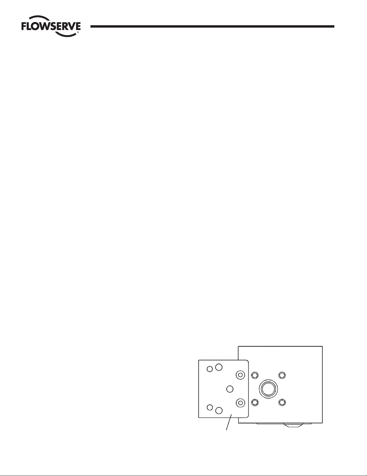
C. CONNECTIONS
Air connections are tapped for
1
/
4" NPT male connectors and are
clearly marked. We recommend use of tape, Loctite®577 or
similar user preferred for sealing.
Port I Input instrument pneumatic signal 20–100 kPa (3–15 psi)
Port S Supply air, maximum 0.9 MPa (125 psi)
Port C1, C2 Actuator connections (0.2–0.9 MPa). C2 opening port.
Connect the air supply line to port S.
For double-acting operation, connect the right-hand and left-hand
ports of the actuator end cap (right-hand end cap when facing
actuator nameplate) to port C2 and C1 respectively.
For single-acting operation, plug port C1 for increasing signal to
open or close. Plug port C2 for decreasing (reverse) signal to
close.
3. OPERATION
The PM15 operates on a force balance principal. Force is originated
by the signal pressure transmitted through a diaphragm onto the
balance arm. The opposing force is achieved through the feedback
spring and is proportional to the position of the lower arm. The lower
arm position is determined by the position of the cam which is
secured to the spindle and connected to the actuator shaft thus
providing the feedback from the actuator/valve. When these two
forces are equal, the balance arm and the spool in the pilot valve is in
a neutral position — the complete unit is in a balanced position. Air is
supplied to the pilot valve through port S, and controls the air flow
through ports C1 and C2.
Assume an equilibrium position.
An increased control pressure will deflect the diaphragm (1) down,
compressing the feedback spring (3). The balance arm (2) moves the
spool (7) in the pilot valve (8) furnishing supply air to the actuator,
while at the same time air is exhausted from actuator and is vented to
atmosphere through the pilot valve.
With the increased supply air, the actuator rotates (or moves linearly)
moving the positioner spindle (6). The spindle and cam (5) rotate,
forcing the lower arm (4) upwards compressing the feedback spring
(3). This motion will continue until two forces are equal and the unit
is an equilibrium position.
Page 4

4 PM15 Pneumatic Valve Positioner Installation, Operation and Maintenance Instructions WCAIM2016
Flow Control Division
Worcester Controls
1
7
8
3
5
6
4
2
1
3
2
4
7
6
5
Correct
Incorrect
3
2
1
1-2 mm (
1
/
16
")
4
Operation Span and Zero Adjustment
Cam Adjustment
4. AIR REQUIREMENTS
Maximum supply pressure is 0.9 MPa (125 psi).
Supply air shall be clean, dry and free from oil, water, moisture,
foreign parts and debris.
The air shall be freeze-dried or similar to a dew point of at least 10˚C
(18˚F) below lowest expected ambient temperature.
A <40 micron filter/regulator is recommended to be installed as close
to PM15 as possible to ensure proper supply air quality.
5. SPAN AND ZERO ADJUSTMENT
Span is adjusted with the brass-colored (upper) thumb wheel (1)
located on the feedback spring.
To adjust the span, always return to minimum input signal first, then
loosen the locking screw (2) and turn thumb wheel (1). Tighten screw
(2) when span is set. Do not allow the top of the spring to contact the
spring guide (3).
Always check zero after adjusting span.
Zero is adjusted by turning the silver (lower) thumb wheel (4) located
on the lower arm (5) or externally with a screwdriver (7), through the
zero adjustment opening. Remember to install cover (6) to ensure the
units sealing.
6. CAM ADJUSTMENT
With the cover and indicator removed, loosen the screw (1) and turn
the cam locking nut (2) counterclockwise until the cam loosens.
Adjust the cam (3) as desired making sure that the ball bearing (4)
always is riding on an active lobe on the cam. To secure the cam,
make sure that screw (1) is backed out from the locking nut (2) then
finger tighten the locking nut and tighten screw (1). Install and adjust
the indicator and reinstall cover.
Page 5

WCAIM2016 PM15 Pneumatic Valve Positioner Installation, Operation and Maintenance Instructions 5
Flow Control Division
Worcester Controls
7. REVERSE-ACTING AND SPLIT-RANGE
Reverse-Acting
For reverse-acting operation, invert cam. Also reverse connections
C1 and C2. For single-acting actuators, move actuator connection
from C2 to C1 and plug C1.
Split-Range
For split-range, reposition the cam, noting the markings on the cam—
for 3–9 psi use initial 50% zone; from 9–15 psi, use 51–100% zone.
8. MAINTENANCE
A. PILOT VALVE
To remove the pilot valve for cleaning or inspection, remove the
screw (1) and carefully lift out the complete assembly (2). Gently
remove the spool (3) from the block and clean the parts, using
methylate cleaner or similar. Blow the parts dry with compressed
air.
Should the parts show signs of wear, a new assembly is
recommended. Mixing spool valves and valve bodies may result
in very high bleed rates and poor performance. Check the O-rings,
then secure and install the pilot valve assembly to the positioner
unit and secure it with the screw (1). Make sure that the leaf
spring (4) on the balance arm (5) is properly fitted in the groove
on spool (6). Check again to ensure smooth operation of the
assembly.
To maintain original factory performance specifications, use only
Worcester spool valve assemblies.
B. DIAPHRAGM
Loosen screws (1) and remove the diaphragm cover (2).
Loosen screw (3), diaphragm (4) and washers (5) can be
removed.
When installing the diaphragm, make sure to place one washer on
each side of the diaphragm. Make sure that the raised circle on
the washer is facing the diaphragm.
Install the screw (3) and tighten.
Check the O-ring on the diaphragm cover (2), then install
and secure the cover with screws (1).
C. FEEDBACK SPRING
Once the front cover and indicator are removed, the
feedback spring can be easily accessed.
Hold the spring (1) from the top, pull down and out.
When installing, hold the assembly at the top, guide the lower
part to position on the zero screw, then press down until it fits
easily under the balance arm (2). Make sure that the assembly is
aligned properly against the lower arm and the notch is engaged
in the tab on the balance arm (2).
D. BALANCE ARM
The balance arm can only be removed after diaphragm and
feedback spring have been removed. (See Section 8.C. and
Section 8.B.)
Loosen the screws (3) and the balance arm can be removed.
When installing the balance arm make sure that the leaf spring (4)
on the underside of the balance arm (5) is properly engaged into
the groove (6) of the spool in the pilot valve.
Tighten the two screws (3) holding the balance arm to the
positioner.
Maintenance — Pilot Valve
Maintenance — Diaphragm
Maintenance — Feedback Spring
3
2
1
6
5
4
2
1
3
5
4
2
1
Page 6

6 PM15 Pneumatic Valve Positioner Installation, Operation and Maintenance Instructions WCAIM2016
E. LOWER ARM
Once the front cover is removed, the lower arm can be easily
accessed. Remove the indicator, feedback spring and the cam.
Loosen screw (2) and remove twist stop (1). Remove screw (3),
lower arm (4), rod (5) and spring (6).
Check rod and lower arm for wear, replace if necessary. Clean the
rod and install it in the lower arm. The lower arm should move
easily and smoothly.
Install the lower arm and rod assembly into the positioner
housing, making sure that the spring (6) is attached properly to
the lower arm and positioner housing.
Secure the lower arm and rod assembly with the screw (3). Check
again that the lower arm moves smoothly.
Apply a small amount of grease on the small tongue on the lower
arm, then install and secure the twist stop.
Install cam, feedback spring, indicator and front cover.
F. O-RINGS
With time and use, O-rings can become brittle. This can cause
poor operation and even failure of the positioner.
Always check O-rings when performing any work on the
positioner and replace bad O-rings.
A thin layer of silicon grease applied on the Buna N (Black) Orings prolongs their life. On Q (Red Silicon) O-rings, use a
non-silicon based grease.
9. TROUBLESHOOTING
NOTE: All PM15 positioners are serialized and date coded. Please note
and provide the serial number when contacting the factory for
troubleshooting or service.
Signal change results in actuator running to end positions:
• Check coupling between positioner and actuator.
• Check cam position and locking screw.
• Check input signal.
Signal change has no effect on the actuator position:
• Check indicator and screw.
• Check air supply to positioner and tubing to the actuator.
• Check input signal to positioner.
• Check diaphragm for damage or leakage.
• Check pilot valve function.
• Check cam for correct setting.
Inaccurate positioning:
• Dirty or worn pilot valve.
• Defective or leaking diaphragm.
• Input signal fluctuates.
• Incorrect sizing of actuator.
• Valve/actuator “stiction”.
• High valve/actuator breakaway torque.
• Loose cam.
Flow Control Division
Worcester Controls
Maintenance — Balance Arm
Maintenance — Lower Arm
3
6
5
4
2
1
5
4
3
6
Page 7

WCAIM2016 PM15 Pneumatic Valve Positioner Installation, Operation and Maintenance Instructions 7
Flow Control Division
Worcester Controls
Exploded Drawing
10. TECHNICAL DATA
Input Signal 20–100 kPa/3–15 psi
Linearity < 0.5%*
Hysteresis < 0.5%*
Repeatability < 0.5%*
Gain Factor at:
80% Load
(Supply Pressure 0.6 MPa/87 psi) 250 kPa/kPa psi/psi +20%
50% Load
(Supply Pressure 0.6 MPa/87 psi) 500 kPa/kPa psi/psi +20%
Air Consumption at Supply Pressure: ± 20%
0.6 MPa/87 psi 7.5 nl/min (0.27 scfm)
Air Delivery at Supply Pressure: ± 20%
0.2 MPa/29 psi 135 nl/min (4.7 scfm)
0.4 MPa/58 psi 240 nl/min (8.4 scfm)
0.6 MPa/87 psi 340 nl/min (11.9 scfm)
Supply Pressure Max 0.9 MPa/125 psi
Temperature Range -20˚C to +85˚C (-4˚F to 185˚F)
Connector Threads
1
/
4" NPT
Weight 1.1 kg/2.4 lb
Housing Die Cast Aluminum
Surface Treatment Epoxy Painting
*Percent of full scale.
Item Qty Description
2, 4, 9, 15, 1 Set P4 Screw Set
18, 19, 20,
27, 30
3 1 P4-3 Front Cover
5 1 P4-5 Indicator Arrow-Standard
6 1 P4-6 Cam Locking Nut
7 1 P4-K1 Cam
8 1 P4-8 Lower Arm Spring
12 1 P4-12 Balance Arm
13, 14 1 P4-13 Adapter Plate
16, 17 1 P4-17 Diaphragm Cover with Nitrile O-Ring
Item Qty Description
20, 21 1 P4-20 Diaphragm Assembly/Nitrile
23 1 P4-C3 Spindle
24 1 P4-24 Mounting Hole Sealing Cap
25 1 P4-25 Zero Adjust Cover
26 1 P4-26 Lower Arm Stop Plate
28 1 P4 O-Ring Set, Nitrile
29 1 P4-29 Pilot Valve Assembly
31, 10, 11 1 P4-31 Lower Arm Assembly
32 1 P4-32 P4 Spring Assembly, 12 psi
33 1 P4-33 Guide Rod
11. SPARE PARTS LIST
Page 8

Flow Control Division
Worcester Controls
Flowserve Corporation has established industry leadership in the design and manufacture of its products. When properly selected, this Flowserve product is designed to perform its intended function
safely during its useful life. However, the purchaser or user of Flowserve products should be aware that Flowserve products might be used in numerous applications under a wide variety of industrial
service conditions. Although Flowserve can (and often does) provide general guidelines, it cannot provide specific data and warnings for all possible applications. The purchaser/user must therefore
assume the ultimate responsibility for the proper sizing and selection, installation, operation, and maintenance of Flowserve products. The purchaser/user should read and understand the Installation
Operation Maintenance (IOM) instructions included with the product, and train its employees and contractors in the safe use of Flowserve products in connection with the specific application.
While the information and specifications contained in this literature are believed to be accurate, they are supplied for informative purposes only and should not be considered certified or as a guarantee of
satisfactory results by reliance thereon. Nothing contained herein is to be construed as a warranty or guarantee, express or implied, regarding any matter with respect to this product. Because Flowserve
is continually improving and upgrading its product design, the specifications, dimensions and information contained herein are subject to change without notice. Should any question arise concerning
these provisions, the purchaser/user should contact Flowserve Corporation at any one of its worldwide operations or offices.
For more information about Flowserve Corporation, contact www.flowserve.com or call USA 1-800-225-6989.
FLOWSERVE CORPORATION
FLOW CONTROL DIVISION
1978 Foreman Drive
Cookeville, Tennessee 38501 USA
Phone 931 432 4021
Fax 931 432 3105
www.flowserve.com
© 2003 Flowserve Corporation, Irving, Texas, USA. Flowserve and Worcester Controls are registered trademarks of Flowserve Corporation. WCAIM2016 10/03 Printed in USA
 Loading...