

Page 1

NORDSTROM HYPREGUN®–PLUS 5Q
Assembly, Operation and
Maintenance Manual
Page 2

Contents
Nordstrom Valve Sealants............................................................. 2
Functions of Nordstrom Valve Sealants ........................................ 3
Hypregun-Plus 5Q ........................................................................ 4
Illustrations ............................................................................ 5 & 6
Parts List ...................................................................................... 7
Flow Control
Nordstrom Valves
Nordstrom Valve Sealants
At Flowserve Nordstrom Valves, our primary goal is to serve
lubricated valve users with the highest quality sealant and
sealant injection equipment.
We offer:
• A broad variety of valve sealants
• A flexible service-oriented manufacturing
facility providing outstanding quality control
• An experienced, dedicated staff ready to serve
your needs
Replacement Parts and Kits ................................................... 8 & 9
Assembly Instructions .......................................................10 & 11
Operation .................................................................................... 12
Care and Maintenance ................................................................ 13
Sealant Delivery ..........................................................................14
Troubleshooting Guide ................................................................ 15
Customer Assistance ..................................................................16
Nordstrom Valves success comes from customer service.
Competent, experienced personnel handle your orders from
development ... to order entry ... to manufacturing ... to
shipping.
We supply the most advanced formulations.
Our high-quality sealants range from -85°F to 700°F (-65°C to
371.1°C) ... and from air and water applications to the most
aggressive line fluids.
Consult your authorized Nordstrom Distributor for
information on valve sealants.
2
NORDSTROM HYPREGUN-PLUS 5Q
Page 3

Flow Control
Nordstrom Valves
Functions of Nordstrom Valve Sealants
1. Drop-Tight Seal - To secure an absolutely tight seal,
the film of the sealant works to form a seal between the
sealing surfaces of the valve. The seal is formed by sealant
transmitted through a system of passageways around the
valve port. With proper selection of sealant for your particular
service, the seal can be retained over a wide range of temperatures and pressures.
2. Lubrication - Prevents metal-to-metal contact of the valve
sealing surfaces by filming over bearing irregularities. No
matter how finely ground a metal surface may be, the metal is
a series of tiny peaks and valleys. As one metal surface slides
against another, friction is set up and adhesion, shearing,
or plowing may result. A protective film of sealant over the
bearing area prevents metal-to-metal rubbing.
3. Renewable Seat - There is no need to disassemble a
lubricated valve or remove it from service to replace mildly
damaged seats. Sealant, as a structural part of lubricated
valves, provides a flexible and renewable seat, eliminating
the necessity of force fit contact to effect a seal. For this
purpose, the sealant not only must have proper plasticity, but
also resistance to line fluids such as solvents and chemicals.
Sealant forms a seal between the sealing surfaces of the valve
even under pressure.
4. Plug Jacking - The fundamental operating principle of the
traditional lubricated plug valve design lies in the application
of Pascal’s Law. The law states that a unit pressure applied to
the liquid contained in a sealed vessel is transmitted to every
part of the liquid with undiminished force, thus multiplying
the force many times, depending on the area of the interior of
the vessel. The sealant, under pressure developed by sealant
injection, supplies the hydraulic means for lifting the plug
from its tapered seat when and if that force is needed to
free the plug.
Nordstrom Valves offers
more than twenty five
varieties of sealants
for plug, ball, and gate
valves. Stick and bulk
grades are available in
most formulas.
NORDSTROM HYPREGUN-PLUS 5Q
3
Page 4

Hypregun-Plus 5Q
Flow Control
Nordstrom Valves
The Flowserve Nordstrom Hypregun-Plus 5Q was developed
using the original Nordstrom Hypregun design and modifications
as suggested by many Hypregun owners. This design continues to
meet field and plant maintenance needs of valve users.
The Hypregun-Plus 5Q is ideal for large scale valve servicing
in refineries, compressor stations, gasoline plants, cycling plants,
pipelines, and manifold installations.
The Hypregun-Plus 5Q is a compact, highly efficient, air
operated sealant injection device with a 100:1 pressure ratio,
double acting piston, and five quart can. Continued positive
pressure applied to the side cylinders assures intimate contact
between the follower plate and sealant. Positive pressure makes
it possible for the Hypregun-Plus 5Q to pump sealant at a much
lower temperature than is possible with dispensing equipment
without this feature.
The follower plate is engineered to promote flow of sealant
to the foot valve at all workable air pressures, but air pressures
between 100 and 125 psi (6.9 to 8.6 bar) give the most efficient
operation. Lower air pressure can be used but the gun delivery
volume will be reduced accordingly. It is important that the gun
not be used on air pressures exceeding the 125 psi (8.6 bar)
rating of the air motor. The air motor uses a maximum of 11.4
cubic feet of air per minute when operated at 125 psi (8.6 bar) air
pressure and with zero load. Reduced air pressure and increased
load reduce air consumption although not linearly.
The amount of sealant delivered by the Hypregun-Plus 5Q
depends on available air pressure to the gun, type of sealant and
the temperature at which the sealant is dispensed.
A moisture trap (not supplied with the gun) for use on
air sources containing appreciable amounts of water is quite
advantageous for low temperature applications. Moisture, if
allowed to reach the air motor, can condense and freeze, causing
the air motor to stall. Air line filters for removing moisture from
the air supply are available from several manufacturers.
The Hypregun-Plus 5Q is designed to use five-quart
(4.7 litre) sealant cans, which have been materially strengthened
with welded seams. These cans are standard containers for all
Nordstrom bulk sealants. The can shield supplied with each gun
gives added strength to the can.
The five-quart (4.7 litre) can and shield have been developed
specifically for use with the Hypregun-Plus 5Q. We do not
recommend using other containers or sealants developed
by other manufacturers.
How to get the most out
of your Hypregun-Plus 5Q
The following suggestions will ensure efficient and continued
operation of the gun:
• If the air motor operates slowly because of low temperatures or
other causes, introduce light machine oil into the motor through
the air supply. This will, in most cases, free a stalled air motor
and permit it to operate more efficiently.
• Remove any service sealant from the exposed portion of the
pumping mechanism to reduce drag and prevent sealant from
entering portions of the gun not designed for this purpose.
• Provide a means of removing moisture from the air supply
to the gun if used at subfreezing temperatures. Use of air
filters should accomplish
this purpose.
• Do not damage the thin walled cylinder surrounding the piston
of the air motor. Any imperfection in this cylinder will reduce
the effectiveness of the gun and shorten its life.
4
NORDSTROM HYPREGUN-PLUS 5Q
Page 5
Flow Control
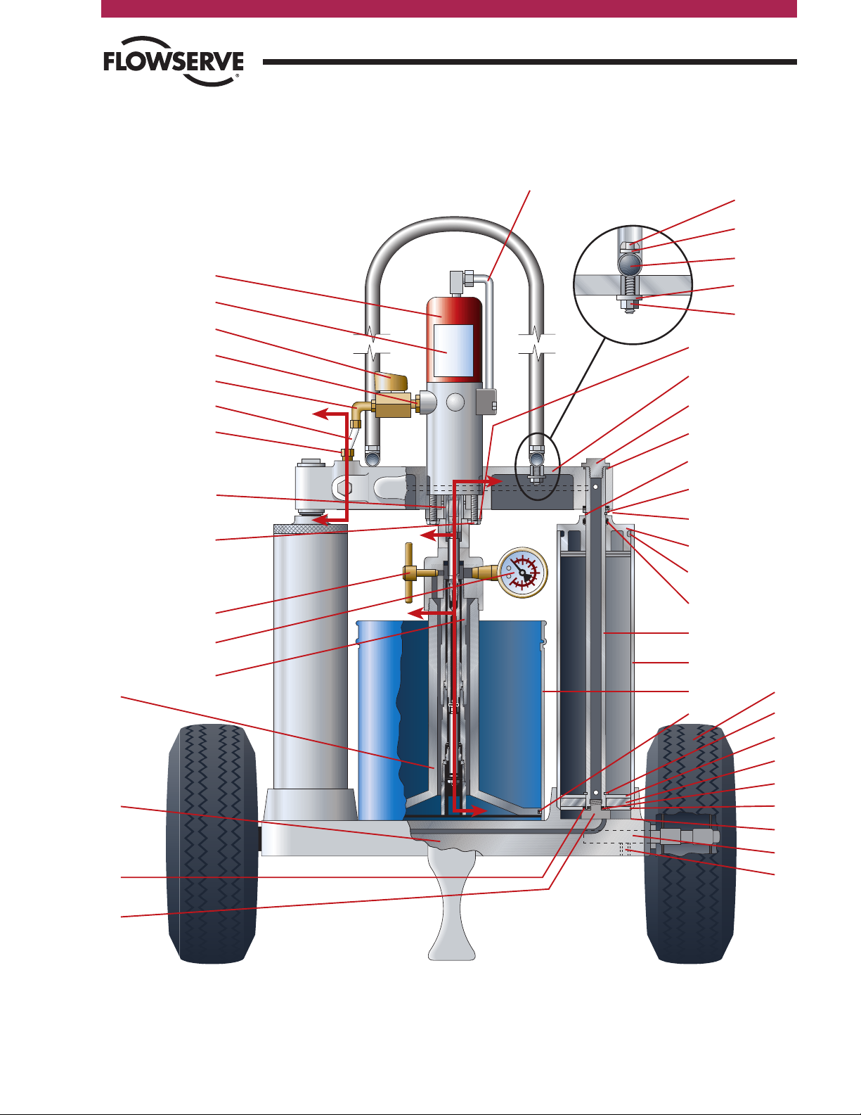
Figure 1
79
1
27
25
26
24
62
21
75
81
34
11
23
18
72
19
22
29
28
20
27
11
60
11
16
12
15
3
6
5
91
54
13
63
65
36
70
90
32
61, 88
32
31
Detail-1
A
A
C
B
B
C
6
99
35
Nordstrom Valves
Illustration
NORDSTROM HYPREGUN-PLUS 5Q
5
Page 6
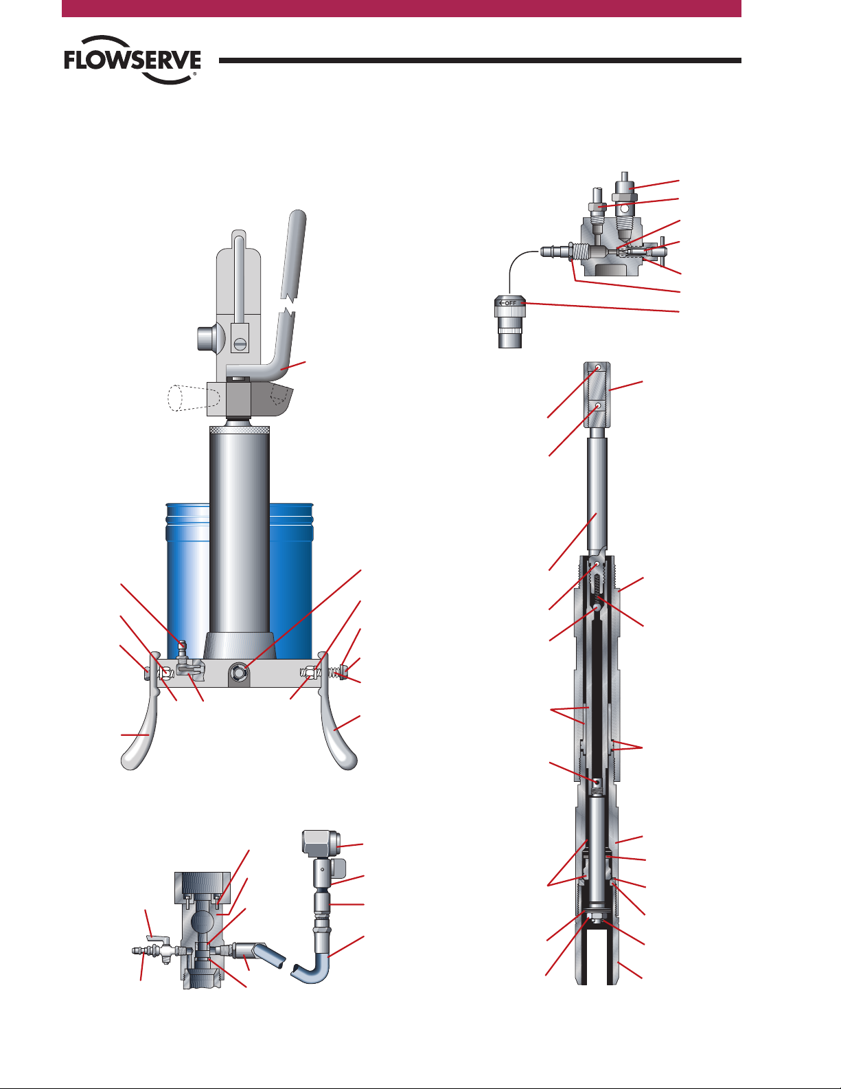
Illustration
57
86
87
74
83 30 85 74
84
82
83
77
71
Figure 2
(Side View Less Wheel)
76
Section A-A
4
6
9
10
7
17
8
Section B-B
64
57 59
67
89
33
14
69
78
68
66
Section C-C
51
49
47
45
38
40
38
37
55
53
50
52
48
46
44
43
42
54
39
41
Flow Control
Nordstrom Valves
6
NORDSTROM HYPREGUN-PLUS 5Q
Page 7

Flow Control
Nordstrom Valves
Parts List
Figure 1
Ref. Part Name Part Number Qty. Reqd.
1 Air motor 1900037 1
3 Throttle valve 927325 1
5 Nylon air tube 60023 1
6 Straight male connector 1927418 1
11 O-ring 934014 6
12 Yoke 40866 1
13 Hex head capscrew 910007 2
15 Lock washer 932525 2
16 Yoke retaining screw 40867 2
18 Base 60001 1
19 Cylinder 40869 2
20 Cylinder head 40870 2
21 Cylinder gasket 40871 2
22 Piston rod 40872 2
23 Piston retaining screw 40873 2
24 O-ring 934008 2
25 Piston retaining washer 40874 2
26 Piston packing 40875 2
27 Retaining ring 927338 4
28 O-ring 934309 2
29 O-ring 934015 2
34 Follower 40880 1
35 O-ring 934068 1
36 Down tube assembly 60018 1
54 Coupling 1900312 1
60 Yoke retaining washer 40890 2
62 Piston retaining washer for O-ring 41121 2
63 Valve screw 1900051 1
65 Pressure gauge 1900052 1
70 Nameplate 1900200 1
72 Can shield 60003 1
75 Axle 1900018 2
79 Wheel 60012 2
81 3/8" – 16 x 1/2" setscrew 1900034 2
91 Metal air tube assembly 1900132 1
93 90° male connector 927417 1
99 Hex bushing 904273 1
Detail 1
Ref. Part Name Part Number Qty. Reqd.
31 Hex capscrew 910334 2
32 Washer 900836 4
61 Spacer 1939100 2
88 Pipe plug 2761011 2
90 Lock nut 1939115 2
Section A-A
Ref. Part Name Part Number Qty. Reqd.
4 Relief valve 1900008 1
6 Straight male connector 1927418 1
7 Nipple 927310 1
8 Ram needle valve 1900039 1
9 O-ring 934003 1
10 Gasket - fiber 927330 1
17 Air coupler 927308 1
Figure 2
Ref. Part Name Part Number Qty. Reqd.
30 Restrictor ell assembly 40876 1
57 Nipple 927309 1
71 Handle 1900068 1
74 Kick stand 60005 2
76 Spring 60008 1
77 Retaining ring 904672 2
82 3/8" steel washer 932602 1
83 3/8" medium steel lock washer 932527 2
84 3/8" x 2" steel hex head capscrew 902278 1
85 3/8" – 16 steel nut 900085 1
86 Hex nut 920402 1
87 5/16" – 18 x 1-1/4" steel hex head
capscrew
Section B-B
Ref. Part Name Part Number Qty. Reqd.
14 Socket head capscrew 939005 4
33 Pump body w/packing 1900019 1
57 Nipple 927309 1
59 Gasket 1900050 1
64 Relief valve 927348 1
66 Hose, 10 foot 1900053 1
67 Swivel - L type 927343 1
68 Swivel - straight type 927437 1
69 Button head coupler 64584 1
78 Shutoff & relief valve 60010 1
89 Piston packing 1900064 1
Section C-C
Ref. Part Name Part Number Qty. Reqd.
37 Air motor piston rod 1900300 1
38 Roll pin 1900301 2
39 Spring 1900047 1
40 Steel ball 1900040 1
41 Tube extension 1900302 1
42 Piston & cylinder 1900303 1
43 Gasket 1900049 2
44 Extension 1900304 1
45 Primer rod & foot valve assembly 1900305 1
46 Foot valve stop washer 40886 1
47 Gasket 1900307 1
48 Valve seat 1900306 1
49 Steel washer, special 1900308 1
50 Primer body 1900310 1
51 Hex nut 1900041 1
52 Cotter pin 931000 1
53 Roll pin 1900311 1
54 Coupling 1900312 1
55 Roll pin 1900313 1
909208 1
NORDSTROM HYPREGUN-PLUS 5Q
7
Page 8

Replacement Parts and Kits
Flow Control
Nordstrom Valves
Major Repair Kit #1900061
Part Part
Qty. Number Description
1 47524 Button head coupler repair kit
1 1900016 Down tube kit
Minor Repair Kit #1900059
Part Part *
Qty. Number Description
2 40871 Gasket (21)
2 40875 Packing (26)
1 927330 Gasket, fiber (10)
4 927338 Retaining ring (27)
1 934003 O-ring (9)
2 934008 O-ring (24)
6 934014 O-ring (11)
2 934015 O-ring (29)
1 934068 O-ring (35)
2 934309 O-ring (28)
1 1900039 Ram needle valve (8)
1 1900051 Valve screw (63)
Down Tube Kit #1900016
Part Part *
Qty. Number Description
1 40886 Foot valve stop washer (46)
1 931000 Cotter pin (52)
1 1900040 Steel ball (40)
1 1900041 Hex nut (51)
1 1900047 Spring (39)
2 1900049 Gasket (43)
1 1900050 Gasket (59)
1 1900064 Piston packing (89)
2 1900301 Roll pin (38)
1 1900303 Piston & cylinder (42)
1 1900305
1 1900306 Valve seat (48)
1 1900307 Gasket (47)
1 1900308 Steel washer (49)
Primer rod & foot valve assy. (45)
(1)
(1)
Button Head Coupler
Repair Kit #47524
Part Part
Qty. Number Description
1 64585 Spring
1 64586 Washer
1 934008 O-ring
1 64582 Valve
(1)
Wheel Kit #1900080
(single wheel only)
Part Part *
Qty. Number Description
1 60012 Wheel (79)
1 904672 Retainer ring (77)
1 1900018 Axle (75)
1 1900034 Setscrew (81)
Kick Stand Kit #1900162
(single kick stand only)
Part Part *
Qty. Number Description
1 60005 Kick stand (74)
1 60008 Spring (76)
1 900085 Nut (85)
1 902278 Capscrew (84)
1 909208 Capscrew (87)
1 932527 Lock washer (83)
1 932602 Washer (82)
1 920402 Nut (86)
Hypregun-Plus 5Q
Hoses by Length
(1/2" – 27 Female each end)
Hose Part Hose Part
Length Number Length Number
6 ft. 47504 25 ft. 47506
10 ft. 1900053 30 ft. 47507
12 ft. 1900032 50 ft. 47508
15 ft. 47535 75 ft. 1900022
20 ft. 47505
* Numbers in parentheses denote illustration number
(1)
Component of Major Repair Kit 1900061
88
Air Supply Assembly #1900120
Part Part *
Qty. Number Description
1 60023 Nylon air tube (5)
1 927417 90° male connector (93)
1 1927418 Straight male connector (6)
Connectors are complete with nut and ferrule.
NORDSTROM HYPREGUN-PLUS 5Q
Page 9

Flow Control
Nordstrom Valves
Replacement Parts and Kits
Miscellaneous Repair Parts
Illustration Part Part
Number Number Description
Figure 1, Page 5
1 1900037 Air motor
47510 Air motor repair kit
3 927325 Throttle valve
5 60023 Nylon air tube
6 1927418 Straight male connector
11 934014 O-ring
(7)
(2)
12 40866 Yoke
13 910007 Hex head capscrew
15 932525 Lock washer
16 40867 Yoke retaining screw
18 60001 Base
19 40869 Cylinder
20 40870 Cylinder head
21 40871 Cylinder gasket
(2)
22 40872 Piston rod
23 40873 Piston retaining screw
24 934008 O-ring
25 40874 Piston retaining washer
26 40875 Piston packing
27 927338 Retaining ring
28 934309 O-ring
29 934015 O-ring
34 40880 Follower
35 934068 O-ring
(2)
(2)
(2)
(2)
(2)
(2)
36 60018 Down tube assembly
54 1900312 Coupling
60 40890 Yoke retaining washer
62 41121 Piston retaining washer for O-ring
63 1900051 Valve screw
65 1900052 Pressure gauge - 15,000 psi
70 1900200 Nameplate
72 60003 Can shield
75 1900018 Axle
79 60012 Wheel
81 1900034 Setscrew
(2)
(6)
(4)
(4)
(4)
91 1900132 Metal air tube assembly
93 927417 90° male connector
99 904273 Hex bushing
Section A-A, page 6
4 1900008 Relief valve
6 1927418 Straight male connector
7 927310 Nipple
8 1900039 Ram needle valve
9 934003 O-ring
(2)
10 927330 Gasket, fiber
(2)
(2)
17 927308 Air coupler
(2)
Component of minor repair kit 1900059
(3)
Component of down tube kit 1900016
(4)
Component of wheel kit 1900080
(5)
Component of kick stand kit 1900162
(6)
Not available as repair part
(7)
Nylon air tube not available with nuts and ferrules - see air
supply assembly 1900120 on page 8
(8)
Complete with nuts and ferrules
NORDSTROM HYPREGUN-PLUS 5Q
Illustration Part Part
Number Number Description
(Figure 2, page 6)
30 40876 Restrictor ell assembly
57 927309 Nipple
71 1900068 Handle
74 60005 Kick stand
76 60008 Spring
77 904672 Retaining ring
82 932602 Washer
83 932527 Lock washer
84 902278 Capscrew
85 900085 Nut
86 920402 Nut
87 909208 Capscrew
(5)
(5)
(4)
(5)
(5)
(5)
(5)
(5)
(5)
(Section B-B, page 6)
14 939005 Socket head capscrew
33 1900019 Pump body with packing
57 927309 Nipple
59 1900050 Gasket
(3)
64 927348 Relief valve
66 1900053 Hose - 10 foot
67 927343 Swivel - L type
68 927437 Swivel - straight type
69 64584 Button head coupler
78 60010 Shut off and relief valve
89 1900064 Piston packing
(3)
(Section C-C, page 6)
37 1900300 Air motor piston rod
38 1900301 Roll pin
39 1900047 Spring
40 1900040 Steel ball
41 1900302 Tube extension
42 1900303 Piston & cylinder
43 1900049 Gasket
(3)
(3)
(3)
(3)
(3)
44 1900304 Extension
(8)
45 1900305 Primer rod & foot valve
assembly
46 40886 Foot valve stop washer
47 1900307 Gasket
48 1900306 Valve seat
49 1900308 Steel washer
50 1900310 Primer body
51 1900041 Hex nut
52 931000 Cotter pin
53 1900311 Roll pin
54 1900312 Coupling
(3)
(3)
(3)
(3)
(3)
(3)
(3)
(3)
(3)
55 1900313 Roll pin
(Detail-1, page 5)
31 910334 Hex capscrew
32 900836 Washer
61 1939100 Spacer
88 2761011 Pipe plug
90 1939115 Lock nut
9
Page 10

Assembly Instructions
Flow Control
Nordstrom Valves
Numbers in parentheses note the illustration numbers as located on
pages 5 and 6 of this brochure. Refer to this illustration to assist in
assembling your Hypregun-Plus 5Q.
Your Hypregun-Plus 5Q is shipped disassembled. The contents of
the shipping container include:
Part Illustration
Qty. Name Number
2 Wheel 79
2 Axle 75
2 Retaining ring 77
2 Setscrew 81
1 Handle 71
2 Capscrew 31
4 Steel washer 32
2 Lock nut 90
2 Spacer 61
2 Pipe plug 88
2 Kick stand 74
2 Washer 83
1 Hex nut 85
1 Hex nut 86
1 Capscrew 87
1 Capscrew 84
1 Spring 76
1 Washer 82
1 10 foot hose assy.
1 Gun sub-assembly
Assembly
The following instructions reference the front and back of the
Hypregun-Plus 5Q. The integral handle of the yoke (12) is
considered the front of the gun.
Handle Assembly
1. Locate the two drilled holes in the top of the yoke (12).
2. Remove from the parts bag two 5/16" stainless steel hex head
capscrews (31), two 5/16" stainless steel washers (32), two
5/16" stainless steel lock nuts (90), two spacers (61), and two
pipe plugs (88).
3. Position the horseshoe shaped handle (71) with the bend
upward and extending toward the back of the yoke (side
opposite the yoke handle).
4. Install the handle spacers (61) into the open ends of
the handle.
5. Secure the handle using the parts as described in Step 2 and
as illustrated on page 5. The steel washers are to be positioned
between the head of the capscrew and the handle and the lock
nut and the yoke.
6. Tighten using the socket wrenches and socket extension.
7. Insert the pipe plugs (88) into the opens ends of the handle.
Wheel Assembly
1. Locate two wheels (79), two axles (75), two retaining rings
(77), and two setscrews (81).
2. Lay the Hypregun-Plus 5Q on its back.
3. Using pliers, install the retaining ring (77) into the groove on
the end of the axle (75).
4. Place the axle through the hub of the wheel (79) making sure
the axle is inserted from the side of the wheel with the air
valve stem.
5. Insert the axle into the axle hole on the side of the base (18).
6. Insert the setscrew into the drilled and tapped hole in the
bottom of the base and tighten securely using a 3/16" hex
head Allen wrench.
Tools
Tools required for assembly of the Nordstrom
Hypregun-Plus 5Q:
■
Adjustable wrench
■
3/16" Allen wrench
■
1/2" socket (two required)
■
socket wrench (two required)
■
socket extension
■
pliers
1010
NORDSTROM HYPREGUN-PLUS 5Q
Page 11
Flow Control
Nordstrom Valves
Assembly Instructions
Kick Stand Assembly
1. Locate two kick stands (74), one hex nut (85), one hex nut
(86), two washers (83), one capscrew (87), one capscrew (84),
one spring (76), and one washer (82).
2. Locate the kick stand mounting hole on the front of the
base (18).
3. Align the hole in the kick stand with the hole in the yoke.
4. Secure the kick stand into position using capscrew (87), lock
washer (83), and nut (86). The lock washer is to be positioned
between the base and nut.
5. Tighten firmly using the adjustable wrench and socket.
6. Locate the kick stand mounting hole on the back of the base
(18).
7. Align the hole in the kick stand with the
hole in the yoke.
8. Secure the kick stand into position
using capscrew (87), washer (82),
spring (76), lock washer (83), and nut
(85). The washer (82) is to be placed
on the capscrew and the spring against
the washer. This assembly is to be
placed through the kick stand and base
holes. Install the lock washer and hex
nut. The nut should be threaded onto
the capscrew until the threads appear
through the nut. If the nut is tightened
too much, the kick stand spring will be
too compressed to allow for free
movement of the kick stand.
9. Stand the Hypregun-Plus 5Q
upright and place the kickstand in
the down position.
Preparing the
Hypregun-Plus 5Q for Use
1. Using an adjustable wrench, install the hose assembly by
attaching the L-type swivel to the pump body (33).
2. Raise the follower (34) by connecting the air supply hose to the
nipple (57) located on the base (18) of the gun.
3. Remove the can shield (72) and install it on the five-quart (4.7
litre) can of Nordstrom valve sealant. To prevent the can from
splitting at the seam, the can shield should be installed with the
opening on the side of the can shield positioned opposite the
seam on the can. The top and bottom of the can shield should
not overlap the lip of the can.
4. Apply a coating of light machine oil to the follower wiper (35)
before loading the gun with a can of sealant. This will lubricate
the seal and allow for easy entry into the can.
5. The spring loaded kick stand is “kicked” to one side to allow
the gun to be tilted backward and rolled.
NORDSTROM HYPREGUN-PLUS 5Q
11
Page 12

Operation
Flow Control
Nordstrom Valves
The numbers in parentheses refer to Hypregun-Plus 5Q parts as
illustrated on pages 5 and 6 of this manual.
1. The air coupler (17) will be found attached to the nipple (7)
as shown in Section A-A. The air hose connector should be
connected to the air supply hose.
2. Fasten the can shield (72, Figure 1) in place around the fivequart (4.7 litre) sealant can below the reinforcing rib and with
the can seam covered by the retainer.
3. Slightly mound the sealant in the container so that the
concave shaped follower plate can be brought down on the
sealant with a minimum entrapment of air.
4. Raise the pump mechanism and sealant follower plate prior
to inserting the sealant container into the gun. By connecting
the air supply hose to the air supply nipple (57, Figure 2) in
the base of the pump and opening the ram needle valve (8,
Section A-A) the follower (34, Figure 1) will rise sufficiently to
clear the top of the sealant container.
5. Place the can with the can shield in the operating position in
the Hypregun-Plus 5Q.
6. Be sure the valve screw (63, Figure 1) in the pump body is
closed. Connect the air supply hose to the nipple (7, Section
A-A). The ram needle valve should be opened slowly causing
the air pressure to force the follower plate (34, Figure 1) down
toward the sealant container.
CAUTION - Keep fingers clear as the follower plate
descends into the sealant container
Care should be exercised that the sealant container is
directly under the follower plate as the two are brought into
contact. Once the follower plate has entered the top of the
sealant container, open the ram needle valve 2 1/2 turns
from closed position.
7. As shown in Section B-B, the relief valve (64) is opened fully
while the valve screw (63, Figure 1) is opened two turns.
8. With the air motor throttle valve closed (3, Figure 1), allow
the column between the sealant container and relief valve
(64, Section B-B) to fill with sealant with the pressure of the
follower plate alone. After a steady flow of sealant is obtained
at the relief valve, open the throttle valve and pump sealant
through the vent valve until there are no air bubbles. (If the
available line pressure is not sufficient to push sealant through
the relief valve by the follower plate pressure alone, open the
air motor throttle valve before the sealant comes out the vent
valve.)
9. After venting of the air is complete, close the valve screw
(63, Figure 1) and the relief valve (64, Section B-B) and read
the pressure gauge (65, Figure 1). If the pressure gauge does
not read several thousand pounds sealant pressure, the relief
valve (64) and the valve screw (63) should be opened again
to allow further venting. Repeat this operation as required.
Occasionally, The Hypregun-Plus 5Q may become air bound
during operation. If this occurs, repeat the procedure for air
venting as outlined above.
10. With the shut-off and relief valve (78, Section B-B) in the
closed position, the button head coupler (69, Section B-B)
should be slipped over the button head fitting on the valve to
be injected. Open the shut-off valve (a small wrench may be
required). Adjust the air throttle valve (3, Figure 1) on the air
motor and observe sealant pressure on the gauge (65, Figure
1) to ensure proper sealant flow and pressure for plug valves.
WARNING - High pressure injection of sealant into
low pressure iron and semi-steel bodied valves
may deform or destroy certain valve parts which
could result in personal injury. Follow the valve
manufacturers recommended procedures for
sealant injection.
11. After the valve is injected with sealant, close the shut-off
and relief valve (78, Section B-B). Remove the button head
coupler (69, Section B-B) from the fitting on the valve. This
may be done without turning off the air supply to the air
motor. By using the shut-off valve, the user can attach the
coupler or remove it from the fitting with the gun retaining
positive pressure.
12. When all of the sealant has been pumped from the sealant
container, close the throttle valve (3, Figure 1) and transfer
the air supply hose to the air supply nipple (57, Figure 2) on
the base of the gun. With the ram needle valve (8, Section
A-A) open, the gun mechanism is raised, lifting the sealant
container off of the gun base. Close the ram needle valve.
13. Unclip the can shield and remove. Remove the can from the
follower. It may be necessary to attach the air supply to the
relief valve nipple (57, Section B-B) and slowly open the relief
valve (64, Section B-B) 1/4 turn to allow air to enter the can.
The can will be forced from the follower.
14. In changing from one service sealant to another, it is advisable
to purge the gun sealant system. To do this, pump the new
sealant through the delivery hose, with the coupler removed,
until the old sealant has been purged.
15. The pressure relief valve (4, Section A-A) is adjusted at the
factory to 125 psi (8.6 bar) cylinder pressure. Use of the
Hypregun-Plus 5Q at higher pressures can result in damage
to the gun.
16. The air motor is rated at 125 psi (8.6 bar). Do not use the
Hypregun-Plus 5Q on air pressures greater than this figure.
Lower air pressures are recommended where delivery capacity
will be adequate. Do not leave air pressure on the gun
indefinitely when not in use.
12
NORDSTROM HYPREGUN-PLUS 5Q
Page 13

Flow Control
Nordstrom Valves
Care and Maintenance
Suggested
Hypregun-Plus 5Q Care
The following suggestions will ensure efficient and continued
operation of the Hypregun-Plus 5Q.
1. Avoid damage to the thin walled cylinder surrounding the
piston of the air motor. Imperfections in this cylinder will
reduce the effectiveness of the gun and shorten its life.
2. Handle the Hypregun-Plus 5Q with care. Prevent any bending
or denting of the pistons or operating parts.
3. Use a clean, dry air source. If air is wet, use a filter on the air
line to remove the water. Install an oiler in the air supply line
using light oil in summer and methanol in the winter.
4. Do not use over 125 psi (8.6 bar) air supply pressure. The
gun will work best between 100 psi (6.9 bar) and 125 psi
(8.6 bar).
5. Always use the can shield and five-quart (4.7 litre) cans that
are crimped and welded. The vertical welded seam on the
can should be placed opposite the opening on the shield. If
the opening on the shield is placed over the seam in the can,
the can seam may separate from the pressure created by the
piston.
6. CAUTION - When inserting a new five-quart (4.7 litre)
can of sealant, be extremely careful. Keep fingers
clear as the follower plate descends into the sealant
container.
Repair Reassembly
There are two places in the reassembly of the Hypregun-Plus
5Q pumping mechanism where the parts should not be rigidly
assembled:
1. When the piston and cylinder (42, Section C-C) are attached
to the air motor piston rod (37, Section C-C), they should only
be hand tight (not wrench tight), the holes aligned, and the
roll pin installed to secure in place.
2. In assembling the primer rod and foot valve assembly (45,
Section C-C) into the piston, it should be pinned in place
with roll pin (38, Section C-C) before it becomes tight. There
should be some “wobble” evident for self-alignment of the
parts. The primer rod and foot valve assembly (45, Section
C-C) and valve seat (47, Section C-C) should be replaced as
a single unit.
Factory Repair Service
Factory repair service is available from Flowserve Nordstrom
Valves. Consult your Authorized Distributor or Nordstrom
Customer Service for more details.
7. Be sure to bleed or vent the Hypregun-Plus 5Q before using.
The more the curvature of the mounded sealant matches the
curvature of the follower plate, the less air will be entrapped
when changing cans. The relief valve (64, Section B-B) should
be opened until a steady stream of sealant is obtained. If the
pressure gauge needle continues to bounce, remove the valve
screw (63, Figure 1) to free entrapped air in that area and, in
rare occasions, remove the pressure gauge to be sure there
is no air entrapped in the connection to it. Improper bleeding
is indicated by a very bouncy action of the pressure gauge
needle at relatively low pressures. If this continues, additional
bleeding is necessary.
8. Store the Hypregun-Plus 5Q and sealant in a reasonably warm
place so that not only the gun but the sealant is at an operable
temperature.
NORDSTROM HYPREGUN-PLUS 5Q
13
Page 14

Sealant Delivery
Sealant Delivery
Hypregun-Plus 5Q sealant delivery is affected by the loading
pressure, ambient temperature, and the viscocity of the sealant
being pumped. The chart below provides laboratory test data
which illustrates sealant delivery under common operating
conditions. Also provided in the chart is comparison data
illustrating the improved performance of the Hypregun-Plus 5Q
over the Hypregun.
The Hypregun-Plus 5Q has also been tested for durability.
After 100 hours of continuous operation at atmospheric pressure
the Hypregun-Plus 5Q performed flawlessly.
Injecting sealant at ambient temperatures much lower than
that represented by the chart is accomplished by using the
practical approach of keeping the gun and sealant in a warm
place and only exposing them to extremely cold conditions
during valve injection.
Flow Control
Nordstrom Valves
Sealant Output Test Data
Hypregun-Plus 5Q Hypregun
oz./min. 13.84 3.34
Strokes/min. 175.00 92.00
oz. Per Stroke .08* .04
Test Sealant 1033 bulk
Temperature 70°F.
Air Supply Pressure 100 psi
* 13 strokes per ounce
14
NORDSTROM HYPREGUN-PLUS 5Q
Page 15

Flow Control
Nordstrom Valves
Troubleshooting Guide
These troubleshooting tips are provided as a means of assisting the consumer in overcoming difficulties encountered with prolonged use of a
Hypregun-Plus 5Q. Part numbers in parentheses denote illustration numbers as listed on pages 5 and 6 of this brochure.
WARNING: Never attempt to repair a Hypregun-Plus 5Q without first disconnecting the air supply.
■ Problem: The air motor (1) is operating but sealant is not
being dispensed.
Cause 1: Air is trapped within the down tube assembly.
Solution 1: Bleed the system as described in sections 7 through 9
on page 12 of this manual.
Cause 2: Loose down tube assembly.
Solution 2: Tighten as needed.
Cause 3: Primer rod and foot valve assembly (45) is worn or pitted.
Solution 3: Rebuild the assembly using down tube kit 1900016.
■ Problem: The sealant can is difficult to remove from the follower.
Cause: Dimensional tolerances of the can and follower are restricting
can movement.
Solution: Remove air supply and attach to nipple (57, Section B-B).
Slowly open the relief valve (64) 1/4 turn to allow air to enter
the can. The can will be forced from the follower.
■ Problem: The air motor (1) does not operate when the throttle
valve (3) is opened.
Cause 1: The movement of internal parts of the air motor is restricted
due to debris being entrapped in the motor.
Solution 1: Replace the air motor.
Cause 2: The thin wall of the air motor cyclinder has been
dented thus restricting movement of internal parts.
Solution 2: Replace the air motor.
Cause 3: The nylon air tube (5) is cracked.
Solution 3: Replace the nylon air tube.
Cause 4: Air supply pressure to gun is too low.
Solution 4: Check output pressure of the air supply.
Cause 5: Air passages to air motor are blocked.
Solution 5: Clean air passages of obstructions.
Cause 6: Obstruction in down tube assembly.
Solution 6: Disassemble the down tube assembly (36), clean,
and reassemble.
Cause 7: Down tube assembly not assembled to proper length.
Solution 7: Disassemble down tube assembly and assemble to
proper length by aligning roll pins (38 - two locations).
Cause 8: Metal air tube (91) on the air motor is crushed.
Solution 8: Remove the metal air tube assembly and replace.
■ Problem: The air motor will operate only 1/2 stroke.
Cause 1: The air motor slide valve is worn or damaged.
Solution 1: Install new air motor repair kit 47510.
Cause 2: Obstruction in down tube assembly (36).
Solution 2: Disassemble the down tube assembly, clean,
and reassemble.
■ Problem: The follower movement into the can is restricted.
Cause 1: Can too small.
Solution 1: Use Nordstrom five-quart (4.7 litre) can with welded seam.
Cause 2: Follower wiper (35) is too large.
Solution 2: Install new wiper.
NORDSTROM HYPREGUN-PLUS 5Q
■ Problem: As follower enters can, sealant bypasses the follower O-ring.
Cause 1: Follower wiper (35) is too small.
Solution 1: Install new wiper.
Cause 2: Can is too large or bent.
Solution 2: Use Nordstrom five-quart (4.7 litre) can with welded seam.
Cause 3: Can swells or distorts.
Solution 3: Install can shield (72).
■ Problem: The follower (34) will not go completely to the bottom of
the can.
Cause: The bottom of the cylinders (19) contain water.
Solution: Remove air pressure from the unit, unscrew the cylinders
and drain the water. Dry the cylinders and check for oxidation
before reassembly.
■ Problem: The air motor (1) operates slowly even with 125 psi
(8.6 bar) air supply pressure.
Cause: Air flow is being restricted to the air motor.
Solution: Replace the nylon air tube (5) or the metal air tube (91).
■ Problem: Yoke will not move.
Cause 1: Nipple (7) blocked.
Solution 1: Remove obstruction from air passages making sure the air
supply is of a clean source.
Cause 2: The ram needle valve (8) is closed.
Solution 2: Slowly open the ram needle valve. Once the follower has made
contact with the can, open the ram needle valve to 2-1/2 turns.
Cause 3: The ram needle valve (8) is blocked.
Solution 3: Remove obstruction from the ram needle valve passage.
Cause 4: Air passages in the yoke (12) are blocked.
Solution 4: Clear obstruction from air passages or replace the yoke.
■ Problem: Yoke will not raise or lower evenly.
Cause 1: Cylinder (19) is dry of lubrication.
Solution 1: Introduce a light air tool oil into the air system. Use an oil
which is compatible with rubber to prevent swelling of the
piston packing.
Cause 2: Piston rods (22) are bent or scored.
Solution 2: Replace damaged piston rod(s).
Cause 3: Piston packing (26) has swollen and is too tight
in cylinder (19).
Solution 3: Replace the piston packing.
Cause 4: Piston packing (26) is too tight in cylinder (19) due
to cylinder distortion.
Solution 4: Replace the cylinder.
Cause 5: Air passages of the base (18) are blocked.
Solution 5: Clean air passages using a stiff wire or replace the base.
■ Problem: The yoke will not raise when the air supply is connected to
the nipple (57).
Cause: The restrictor ell assembly (30) air passage is blocked.
Solution: Clean the air passage using a small, stiff wire or redrill
the air passage hole using a #55 wire gauge drill bit.
15
Page 16
Flow Control
Nordstrom Valves
Authorized Distributors
For detailed information on these and other Nordstrom products, call your customer service
representative for the name and number of the nearest authorized Nordstrom distributor.
Flowserve Nordstrom Valves
Flowserve Corporation
1-800-225-6989
Email: nmkt@flowserve.com
or visit www.flowserve.com
1511 Jefferson Street
Sulphur Springs, Texas 75482
USA
United States
Telephone: 903-885-4691 or 4693
FAX: 903-439-3411
Flowserve Corporation has established industry leadership in the design and manufacture of its products. When properly selected, this Flowserve product is designed to perform its intended function safely
during its useful life. However, the purchaser or user of Flowserve products should be aware that Flowserve products might be used in numerous applications under a wide variety of industrial service
conditions. Although Flowserve can (and often does) provide general guidelines, it cannot provide specific data and warnings for all possible applications. The purchaser/user must therefore assume
the ultimate responsibility for the proper sizing and selection, installation, operation, and maintenance of Flowserve products. The purchaser/user should read and understand the Installation Operation
Maintenance (IOM) instructions included with the product, and train its employees and contractors in the safe use of Flowserve products in connection with the specific application.
While the information and specifications contained in this literature are believed to be accurate, they are supplied for informative purposes only and should not be considered certified or as a guarantee of
satisfactory results by reliance thereon. Nothing contained herein is to be construed as a warranty or guarantee, express or implied, regarding any matter with respect to this product. Because Flowserve is
continually improving and upgrading its product design, the specifications, dimensions and information contained herein are subject to change without notice. Should any question arise concerning these
provisions, the purchaser/user should contact Flowserve Corporation at any one of its worldwide operations or offices.
For more information about Flowserve Corporation, contact www.flowserve.com or call USA 1 800 225 6989.
© 2005 Flowserve Corporation, Irving, Texas, USA. Flowserve and Nordstrom Valves are registered trademarks of Flowserve Corporation.
Latin America
Telephone: 903-439-3407
FAX: 903-439-3411
Other Countries
Telephone: 903-885-4692
FAX: 903-439-3404
FCD NVAIM2003-00
Printed in USA.
 Loading...