

Page 1
USER INSTRUCTIONS
PLEUGER® standard submersible
motor pumps
Installation
Operation
Maintenance
Submersible motor pumps with water filled motor
for deep-well installation
PCN=71569293 01-13 (E) (Based on 1042.277/7.)
Original instructions.
These instructions must be read prior to installing,
operating, using and maintaining this equipment.
Page 2

PLEUGER STANDARD USER INSTRUCTIONS ENGLISH 71569293 01-13
CONTENTS
Page
1 INTRODUCTION AND SAFETY ............................ 3
1.1 General ........................................................... 3
1.2 CE marking and approvals .............................. 3
1.3 Disclaimer ....................................................... 3
1.4 Copyright ......................................................... 3
1.5 Duty conditions ................................................ 3
1.6 Safety .............................................................. 4
2 TRANSPORT AND STORAGE .............................. 9
2.1 Consignment receipt and unpacking............... 9
2.2 Handling and lifting.......................................... 9
2.3 Storage .......................................................... 10
2.5 Recycling and end of product life .................. 10
3 DESCRIPTION .................................................... 10
3.1 Technical data ............................................... 10
3.2 Delivery contents ........................................... 10
3.3 General data ................................................. 11
3.4 General description ....................................... 11
3.5 Submersible motor ........................................ 12
3.6 Pump and check valve .................................. 13
4 INSTALLATION .................................................... 14
4.1 Hydraulic installation ..................................... 14
4.2 General advice for installation ....................... 14
4.3 Flexible hose riser pipe ................................. 14
4.4 Centralizers ................................................... 14
4.5 Checks before installation ............................. 14
4.6 Installation of pre-assembled pump units ..... 15
4.7 Riser pipes with flange connections.............. 15
4.8 Riser pipe with pipe socket ........................... 15
4.9 Assembly of submersible motor pumps
before installation ........................................ 15
Page
6 MOTOR FILLING ................................................ 21
6.1 Antifreeze ...................................................... 21
6.2 Type of use ................................................... 22
6.3 Filling quantities ............................................ 22
6.4 Accessories and hardware for filling
and topping up ............................................ 22
6.5 General information about filling ................... 22
6.6 Filling instructions ......................................... 23
7 COMMISSIONING, START-UP
AND SHUTDOWN ........................................... 31
7.1 Commissioning ............................................. 31
7.2 Operation ...................................................... 31
7.3 Switching off the unit ..................................... 32
8 MAINTENANCE .................................................. 32
8.1 General information ...................................... 32
8.2 Pump units .................................................... 32
8.3 Measuring insulation ..................................... 32
8.4 Removal of the pump unit ............................. 33
8.5 Overhaul of the pump unit ............................ 33
9 FAULTS; CAUSES AND REMEDIES .................. 35
10 CERTIFICATION ............................................... 37
5 ELECTRICAL CONNECTIONS ........................... 16
5.1 Motor ............................................................. 16
5.2 Protective measures against
shock-hazard voltage .................................. 16
5.3 Motor protection ............................................ 17
5.4 Short circuit protection .................................. 17
5.5 Motor connection diagrams ........................... 18
5.6 Adjustments for soft-starter and
soft stop devices ......................................... 20
5.7 Operation of submersible motors with
static frequency converter ........................... 20
5.8 Resistance sensor PT100 (RTD) .................. 21
Page 2 of 40 flowserve.com
Page 3
PLEUGER STANDARD USER INSTRUCTIONS ENGLISH 71569293 01-13
1 INTRODUCTION AND SAFETY
1.1 General
These instructions must always be kept
close to the product's operating location or
directly with the product.
Flowserve products are designed, developed and
manufactured with state-of-the-art technologies in
modern facilities. The unit is produced with great
care and commitment to continuous quality control,
utilising sophisticated quality techniques, and safety
requirements.
Flowserve is committed to continuous quality
improvement and being at service for any further
information about the product in its installation and
operation or about its support products, repair and
diagnostic services.
These instructions are intended to facilitate
familiarization with the product and its permitted use.
Operating the product in compliance with these
instructions is important to help ensure reliability in
service and avoid risks. The instructions may not take
into account local regulations; ensure such
regulations are observed by all, including those
installing the product. Always coordinate repair
activity with operations personnel, and follow all plant
safety requirements and applicable safety and health
laws and regulations.
These instructions should be read prior to
installing, operating, using and maintaining the
equipment in any region worldwide. The
equipment must not be put into service until all
the conditions relating to safety noted in the
instructions, have been met.
1.2 CE marking and approvals
It is a legal requirement that machinery and
equipment put into service within certain regions of
the world shall conform with the applicable CE
Marking Directives covering Machinery and, where
applicable, Low Voltage Equipment, Electromagnetic
Compatibility (EMC), Pressure Equipment Directive
(PED), minimum efficiency for some water pumps
(Ecodesign) and Equipment for Potentially Explosive
Atmospheres (ATEX).
Where applicable, the Directives and any additional
Approvals, cover important safety aspects relating to
machinery and equipment and the satisfactory provision
of technical documents and safety instructions.
Where applicable this document incorporates
information relevant to these Directives and Approvals.
To confirm the Approvals applying and if the product is
CE marked, check the serial number plate markings
and the Certification. (See section 9, Certification.)
1.3 Disclaimer
Information in these User Instructions is believed
to be reliable. In spite of all the efforts of
Flowserve Corporation to provide sound and all
necessary information the content of this manual
may appear insufficient and is not guaranteed by
Flowserve as to its completeness or accuracy.
Flowserve manufactures products to exacting
International Quality Management System Standards
as certified and audited by external Quality
Assurance organisations. Genuine parts and
accessories have been designed, tested and
incorporated into the products to help ensure their
continued product quality and performance in use.
As Flowserve cannot test parts and accessories
sourced from other vendors the incorrect
incorporation of such parts and accessories may
adversely affect the performance and safety features
of the products. The failure to properly select, install
or use authorised Flowserve parts and accessories is
considered to be misuse. Damage or failure caused
by misuse is not covered by the Flowserve warranty.
In addition, any modification of Flowserve products or
removal of original components may impair the safety
of these products in their use.
The operational safety of the delivered unit is only
guaranteed for use according to the limitations
described in section 3.1, Technical data. The limits
given in the data sheet may not be exceeded.
1.4 Copyright
All rights reserved. No part of these instructions may
be reproduced, stored in a retrieval system or
transmitted in any form or by any means without prior
permission of Flowserve.
1.5 Duty conditions
This product has been selected to meet the
specifications of your purchaser order. The
acknowledgement of these conditions has been sent
separately to the Purchaser. A copy should be kept
with these instructions.
The product must not be operated beyond
the parameters specified for the application.
If there is any doubt as to the suitability of the
product for the application intended, contact
Flowserve for advice, quoting the serial number.
Page 3 of 40 flowserve.com
Page 4
PLEUGER STANDARD USER INSTRUCTIONS ENGLISH 71569293 01-13
If the conditions of service on your purchase order are
going to be changed (for example liquid pumped,
temperature or duty) it is requested that the user seeks
the written agreement of Flowserve before start up.
1.6 Safety
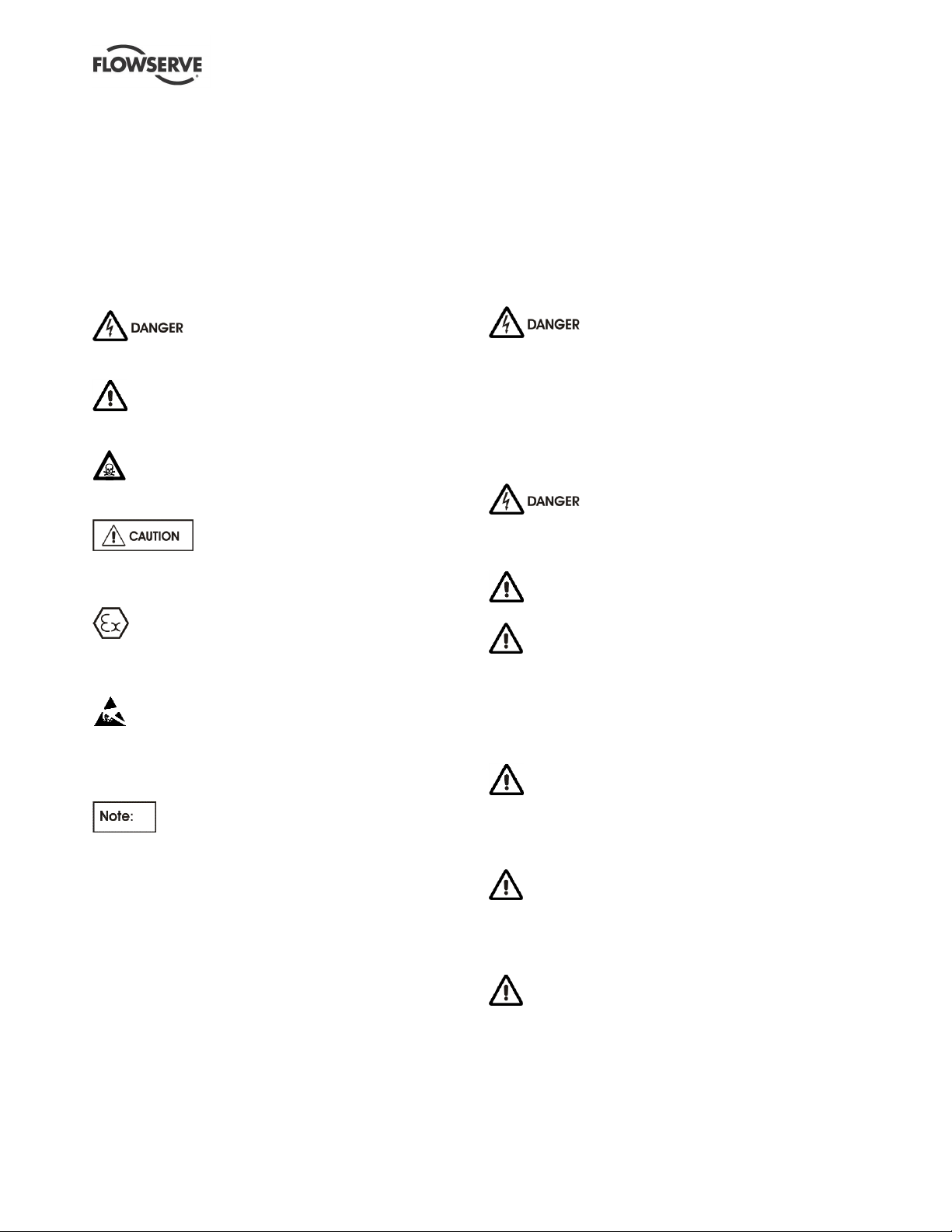
1.6.1 Summary of safety markings
These User Instructions contain specific safety
markings where non-observance of an instruction would
cause hazards. The specific safety markings are:
This symbol indicates electrical safety
instructions where non-compliance will involve a high
risk to personal safety or the loss of life.
This symbol indicates safety instructions where
non-compliance would affect personal safety and could
result in loss of life.
This symbol indicates “hazardous and toxic fluid”
safety instructions where non-compliance would affect
personal safety and could result in loss of life.
This symbol indicates safety instructions
where non-compliance will involve some risk to safe
operation and personal safety and would damage the
equipment or property.
This symbol indicates explosive atmosphere zone
marking according to ATEX. It is used in safety
instructions where non-compliance in the hazardous
area would cause the risk of an explosion.
This symbol is used in safety instructions to
remind not to rub non-metallic surfaces with a dry
cloth; ensure the cloth is damp. It is used in safety
instructions where non-compliance in the hazardous
area would cause the risk of an explosion.
This sign is not a safety symbol but indicates
an important instruction in the assembly process.
1.6.2 Personnel qualification and training
All personnel involved in the operation, installation,
inspection and maintenance of the unit must be
qualified to carry out the work involved. If the personnel
in question do not already possess the necessary
knowledge and skill, appropriate training and instruction
must be provided. If required the operator may
commission the manufacturer/supplier to provide
applicable training.
Always coordinate repair activity with operations and
health and safety personnel, and follow all plant
safety requirements and applicable safety and health
laws and regulations.
1.6.3 Safety action
This is a summary of conditions and actions to
help prevent injury to personnel and damage to
the environment and to equipment. For products
used in potentially explosive atmospheres
section 1.6.4 also applies.
NEVER DO MAINTENANCE WORK
WHEN THE UNIT IS CONNECTED TO POWER
Before maintenance and repair work is started the
motor of the pump unit must first be completely
isolated from the electrical power supply.
The procedure to shut down the unit described in
section 7.3, Switching off the unit, must be followed
without fail.
Danger from electricity must be
eliminated. (For details see, for example, the
regulations of the VDE and local power supply
companies.)
GUARDS MUST NOT BE REMOVED WHILE
THE PUMP IS IN OPERATION
HANDLING COMPONENTS
Many precision parts have sharp corners and the
wearing of appropriate safety gloves and equipment
is required when handling these components. To lift
heavy pieces above 25 kg (55 lb) use a crane
appropriate for the mass and in accordance with
current local regulations.
DISMOUNTING PUMP UNITS
Before dismounting one pump unit, the pump must be
separated from the motor and drained. In case of
dangerous delivery fluids, suitable safety measures
must be made.
THERMAL SHOCK
Rapid changes in the temperature of the liquid within
the pump can cause thermal shock, which can result
in damage or breakage of components and should be
avoided.
HOT (and cold) PARTS
If hot or cold components, or heater or cooler units,
can cause a danger for the operating staff or persons
in the immediate vicinity, measures must be taken to
prevent possible contact, eg by protective gratings.
Page 4 of 40 flowserve.com
Page 5
PLEUGER STANDARD USER INSTRUCTIONS ENGLISH 71569293 01-13
If complete protection is not possible, access to such
devices must be limited to the maintenance staff who
must be informed specifically about the special
dangers by warnings and corresponding signs.
The measures listed above must be applied if the
temperatures in a limited access zone exceed
80 ºC (175 ºF) or fall below -5 ºC (23 ºF), or if the
regional limit values are exceeded.
ADDITIONAL SAFETY NOTES
In addition to the safety notes listed in the main Safety
section, special safety notes in all other sections must
also be observed, eg those for private use.
COMMISSIONING
Prior to each commissioning after installation,
maintenance or repair, follow the instructions and
notes in section 8, Commissioning, switching on,
operation and switching off.
Notes directly attached to the unit must be observed
without fail. These include:
Marking of connections
Rating plate
Rotational direction
HAZARDOUS LIQUIDS
Units handling hazardous liquids must be
decontaminated.
INFLAMMABLE FLUIDS
When the pump is handling hazardous liquids care must
be taken to avoid exposure to the liquid by appropriate
siting of the pump, limiting personnel access and by
operator training. If the liquid is flammable and or
explosive, strict safety procedures must be applied.
When pumping dangerous fluids, no packing
seals must be used.
PREVENT EXCESSIVE EXTERNAL
PIPE LOAD
In horizontally arranged pump units, the pump must not
be used as support for suction or pressure pipework.
Arrange compensators in such a way that the forces
caused by internal pressure do not act upon the pump
flange unless approved in writing by Flowserve.
ROTATIONAL DIRECTION OF THE
MOTOR
The rotational direction of each motor can be found in
the data sheet and or the connection data sheet.
As testing the rotational direction by short startup in
dry conditions is not permitted and as by design the
rotational direction of the motor cannot be determined
when the pump unit is completely mounted, the
rotating field of the power supply must be known. If
necessary, it must be determined using a rotating
field measurement device.
If the pump unit is operated with incorrect rotational
direction, the delivery output is reduced and pump
damage is possible.
OPERATION OF THE PUMP UNIT
The pump unit may only be operated if the unit is
completely mounted, the motor is completely filled
with the prescribed amount of filling fluid and it is
submerged sufficiently into the delivery medium.
Never let the submersible motor pump run dry.
Switching on, including for test purposes, is never
allowed if the pump is not submerged.
For the minimum submersion depth in the delivery
medium, refer to the provided data sheet or ask
Flowserve.
Non-observance can cause the following dangers:
Failure of important system functions
Failure of prescribed methods for maintenance
and upkeep
Danger to persons due to electrical, mechanical
or chemical impact
Danger to the environment by leakage when
delivering hazardous media
OPERATION OF THE PUMP UNIT
Operation with a flow volume that is above average
or does not cause counter-pressure to the pump can
cause a motor overload and cavitation in the pump.
Low flow rates can cause shortened service life of the
pump, overheating of the pump, instability, cavitation
and vibration.
The duty point for which the pump unit has been
designed can be found in the data sheet of the pump.
SWITCHING ON THE PUMP UNIT
After having completely installed the pump unit, close
the outlet valve apart for a small gap to bleed the
riser pipeline. (If the system is equipped with an airrelease valve at the highest point of the riser pipeline,
the outlet valve remains closed.) After switching on,
the pressure at the pressure gauge must be higher
than the pumping head specified in the data sheet,
minus the water depth.
Page 5 of 40 flowserve.com
Page 6
PLEUGER STANDARD USER INSTRUCTIONS ENGLISH 71569293 01-13
Because of the risk of motor overload, S-series units
(pumps with axial impellers) must never be started
against a closed slider!
In order to avoid overheating the pump, a pump must
never be operated for more than 2 minutes against a
closed outlet valve.
In the time during which the empty riser is filled, the
ampere meter can display a higher current after
switch-on than specified in the data sheet, even after
the starting current has subsided.
Afterwards, the operating current must be lower than
the maximum permitted current as specified in the
data sheet.
SLOWLY open the outlet valve so as to not cause
overload to the well due to excessive delivery flow.
Open the slider slowly until the ampere meter displays
the operating current as specified in the data sheet.
After reaching the operating point for which the unit has
been designed, the current intake must approximately
match the one specified in the data sheet.
1.6.4 Products used in potentially explosive
atmospheres
Measures are required to:
Avoid excess temperature
Prevent build up of explosive mixtures
Prevent the generation of sparks
Prevent leakages
Maintain the pump to avoid hazard
The following instructions for pumps and pump units
when installed in potentially explosive atmospheres
must be followed to help ensure explosion protection.
For ATEX, both electrical and non-electrical equipment
must meet the requirements of European Directive
94/9/EC. Always observe the regional legal Ex
requirements eg Ex electrical items outside the EU may
be required certified to other than ATEX eg IECEx, UL.
1.6.4.1 Scope of compliance
Use equipment only in the zone for which it is
appropriate. Always check that the motor and pump
equipment are suitably rated and/or certified for the
classification of the specific atmosphere in which they
are to be installed.
Where Flowserve has supplied only the bare shaft
pump or motor, the Ex rating applies only to that.
The party responsible for assembling the ATEX pump
set shall select any instruments or devices and the
motor cable and joint design and cable protection
suitable to the Ex environment according to ATEX
and IEC 60079-14. Fully submerged submersible
pump sets like electric cables are exempt from ATEX
Ex Marking. IEC 60079-14 requires that the cable
passing through an Ex Zone such as Zone 0, 1, 2, 20,
21 or 22 is correctly rated and protected by a suitable
Conduit or Armour design. Flowserve must be
advised the Ex Zone and area ATEX Classification in
any Caisson or atmosphere so that the appropriate
cable and pump set design is provided for the
application. If the Zone is Zone 0 or 20 a Flowserve
ATEX Category 2 or 3 Marked Pleuger CAVERN
design must not be used. All Pleuger CAVERN
designs use a liquid filled Conduit containing the
electric cable. Any additional applicable equipment
for ATEX must be provided with the necessary CE
Certificate/Declaration of Conformity establishing it is
suitable for the area in which it is to be installed.
The output from a variable frequency drive (VFD) can
cause additional heating effects in the motor and so, for
pump sets with a VFD, the ATEX Certification for the
motor must state that it is covers the situation where
electrical supply is from the VFD. This particular
requirement still applies even if the VFD is in a safe area.
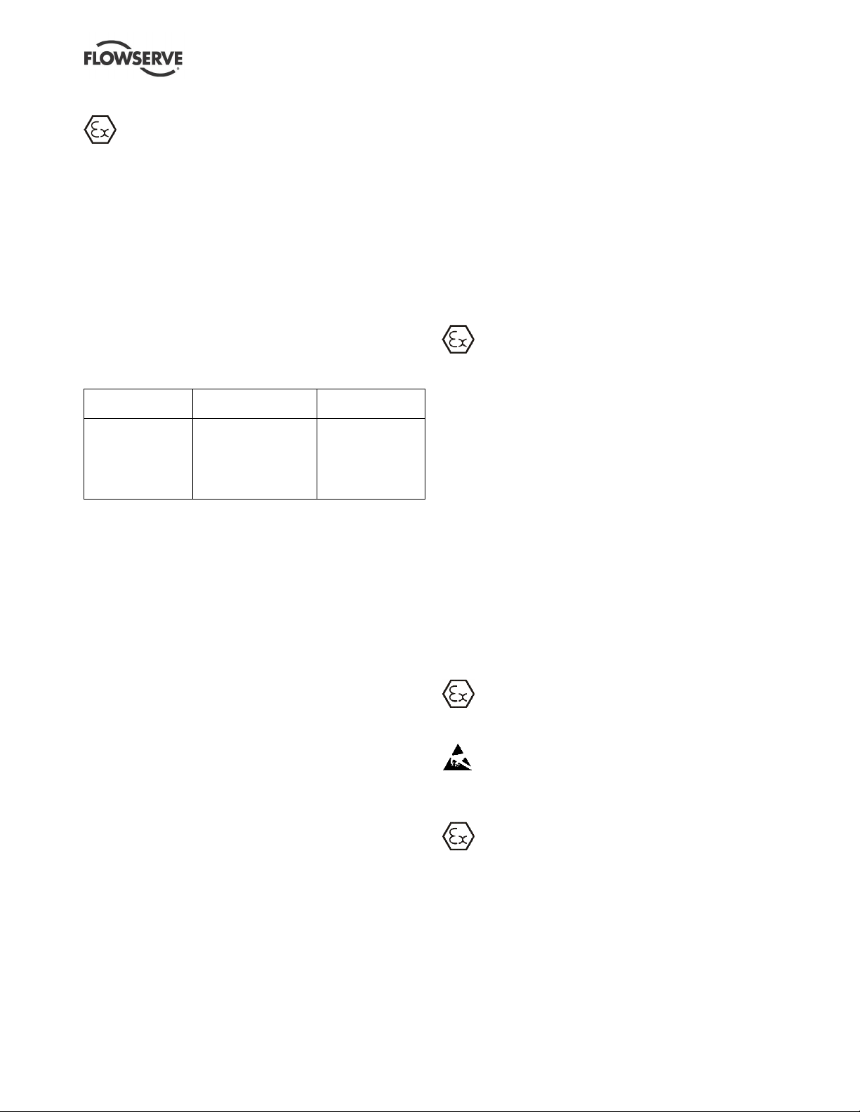
1.6.4.2 Marking
An example of ATEX CAVERN equipment marking is
shown below. The actual classification of the pump
will be engraved on the nameplate.
II 2 GD k IIC T4 T135ºC IP68
Equipment Group
I = Mining
II = Non-mining
Category
2 or M2 = high level protection
3 = normal level of protection
Gas and/or dust
G = Gas, D = Dust
k = Liquid encased protection
(in accordance with EN13463-8)
Gas Group
IIA – Propane (typical)
IIB – Ethylene (typical)
IIC – Hydrogen (typical)
No gas group means suitable for all
Maximum surface temperature (Temperature
Class, see table 1, section 1.6.4.3.)
Protection type when applicable
Page 6 of 40 flowserve.com
Page 7
PLEUGER STANDARD USER INSTRUCTIONS ENGLISH 71569293 01-13
Temperature class
to EN13463-1
Maximum surface
temperature permitted
Temperature limit of
liquid handled *
T6
T5
T4
T3
T2
T1
85 °C (185 °F)
100 °C (212 °F)
135 °C (275 °F)
200 °C (392 °F)
300 °C (572 °F)
450 °C (842 °F)
Consult Flowserve
Consult Flowserve
115 °C (239 °F) *
180 °C (356 °F) *
275 °C (527 °F) *
400 °C (752 °F) *
1.6.4.3 Avoiding excessive surface temperatures
ENSURE THE EQUIPMENT TEMPERATURE
CLASS IS SUITABLE FOR THE HAZARD ZONE
Pumps have a temperature class as stated in the
ATEX Ex rating on the nameplate. These are based
on a maximum ambient of 40 ºC (104 ºF); refer to
Flowserve for higher ambient temperatures.
The surface temperature on the pump is influenced
by the temperature of the liquid handled. The
maximum permissible liquid temperature depends on
the ATEX temperature class and must not exceed the
values in the table that follows:
Table 1: Maximum permitted liquid temperature for
pumps
* The table only takes the ATEX temperature class into consideration.
Pump design or material, as well as component design or material,
may further limit the maximum working temperature of the liquid.
The temperature rise at the seals and bearings and
due to the minimum permitted flow rate is taken into
account in the temperatures stated.
The operator is responsible for ensuring that the
specified maximum liquid temperature is not
exceeded.
Temperature classification “Tx” is used when the liquid
temperature varies and when the pump is required to be
used in differently classified potentially explosive
atmospheres. In this case the user is responsible for
ensuring that the pump surface temperature does not
exceed that permitted in its actual installed location.
Avoid mechanical, hydraulic or electrical overload by
using motor overload trips, temperature monitors or a
power monitor and make routine vibration monitoring
checks.
A vibration check must be carried out routinely. We
recommend a measurement every 4 weeks.
In dirty or dusty environments, make regular checks
and remove dirt from areas around close clearances,
bearing housings and motors.
Where there is any risk of the pump being run against a
closed valve generating high liquid and casing external
surface temperatures fit an external surface
temperature protection device.
For pumps with key drive impellers only
If an explosive atmosphere exists during the
installation, do not attempt to check the direction of
rotation by starting the pump unfilled. Even a short
run time may give a high temperature resulting from
contact between rotating and stationary components.
1.6.4.4 Preventing the build-up of explosive
mixtures
ENSURE THE PUMP IS PROPERLY FILLED
AND VENTED AND DOES NOT RUN DRY
Ensure the pump and relevant suction and discharge
pipeline system is totally filled with liquid at all times
during the pump operation, so that an explosive
atmosphere is prevented.
In addition it is essential to make sure that seal
chambers, auxiliary shaft seal systems and any
heating and cooling systems are properly filled.
If the operation of the system cannot avoid this
condition, fit an appropriate dry run protection device
(for example liquid detection or a power monitor).
To avoid potential hazards from fugitive emissions of
vapour or gas to atmosphere the surrounding area
must be well ventilated.
1.6.4.5 Preventing sparks
To avoid the potential hazard from random
induced current generating a spark, the baseplate
must be properly grounded.
Avoid electrostatic charge: do not rub non-metallic
surfaces with a dry cloth; ensure cloth is damp.
1.6.4.6 Preventing leakage
The pump must only be used to handle liquids
for which it has been approved to have the correct
corrosion resistance.
Avoid entrapment of liquid in the pump and associated
piping due to closing of suction and discharge valves,
which could cause dangerous excessive pressures to
occur if there is heat input to the liquid. This can occur if
the pump is stationary or running.
Page 7 of 40 flowserve.com
Page 8
PLEUGER STANDARD USER INSTRUCTIONS ENGLISH 71569293 01-13
Bursting of liquid containing parts due to freezing
must be avoided by draining or protecting the pump
and ancillary systems.
Locking system for mechanical seals must be
monitored for leaks of the delivery medium and the
locking medium.
Where there is the potential hazard of a loss of a seal
barrier fluid or external flush, the fluid must be monitored.
If leakage of liquid to atmosphere can result in a
hazard, install a liquid detection device.
1.6.4.7 Maintenance to avoid the hazard
CORRECT MAINTENANCE IS REQUIRED TO
AVOID POTENTIAL HAZARDS WHICH GIVE A
RISK OF EXPLOSION
The responsibility for compliance with maintenance
instructions is with the plant operator.
To avoid potential explosion hazards during
maintenance, the tools, cleaning and painting
materials used must not give rise to sparking or
adversely affect the ambient conditions. Where there
is a risk from such tools or materials, maintenance
must be conducted in a safe area.
It is recommended that a maintenance plan and
schedule is adopted. (See section 8, Maintenance.)
1.7 Nameplate and safety labels
1.7.1 Nameplate
For details of nameplate, see the Declaration of
Conformity, or separate documentation included with
these User Instructions.
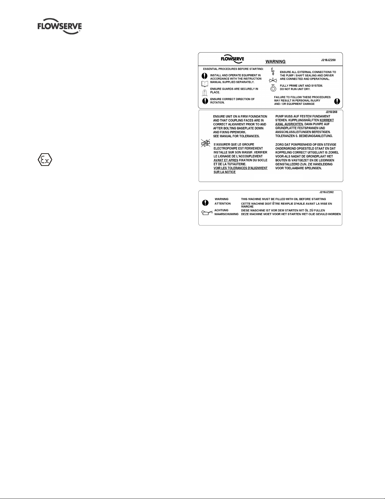
1.7.2 Safety labels
Oil lubricated units only:
1.8 Specific machine performance
1.8.1 General
For performance parameters see section 1.5, Duty
conditions. Where performance data has been supplied
separately to the purchaser these should be obtained
and retained with these User Instructions if required.
1.8.2 Ecodesign
EU regulation 547/2012 of the Directive
2009/125/EC, for the minimum efficiency of defined
classes of water pumps requires that products must
show their Minimum Efficiency Index (MEI) value.
The EU benchmark MEI ≥ 0.70. Also product
information must be available to users.
Performance curves will have been provided with the
quotation or order or are available at flowserve.com.
The efficiency of a pump with trimmed impeller is
usually lower than that of a pump with the full impeller
diameter. Trimming of the impeller will adapt the
pump to a fixed duty point, leading to reduced energy
consumption. The minimum efficiency index (MEI) is
based on the full impeller diameter.
The operation of this water pump with variable duty
points may be more efficient and economic when
controlled by, for example, by the use of a variable
speed drive that matches the pump duty to the system.
Page 8 of 40 flowserve.com
Page 9
PLEUGER STANDARD USER INSTRUCTIONS ENGLISH 71569293 01-13
Information on benchmark efficiency is available at;
www.europump.org/efficiencycharts
EU Regulation 547/2012 requires the statement on a
product nameplate:
MEI ≥ 0.10 [--.-]. (Between 01 January 2013 and
31 December 2014.)
MEI ≥ 0.40 [--.-]. (From 01 January 2015.)
1.9 Noise level
In principle, any noise emission should be avoided as
far as possible at the location of origin. If the noise
protection cannot be reduced by suitable measures to
the values approved by regional laws, the concerned
staff must be provided with personal hearing protection.
Attention must be given to the exposure of personnel
to the noise, and local legislation will define when
guidance to personnel on noise limitation is required,
and when noise exposure reduction is mandatory.
This is typically 80 to 85 dBA.
Submerged motor pumps are in principle submerged
in fluid during operation. This fluid jacket has a
dampening impact so that the noise pressure level of
the units is lower or equal to 70 dB(A). Noise
generation from pipelines and valves must be
evaluated by the operator
2 TRANSPORT AND STORAGE
2.1 Consignment receipt and unpacking
Submersible pumps are subjected to a thorough
inspection before leaving the factory and are supplied
with operating instructions for fitting, starting, care etc
that conform to international safety regulations.
Immediately after receipt of the equipment it must be
checked against the delivery and shipping documents
for its completeness and that there has been no
damage in transportation. Any shortage and or damage
must be reported immediately to Flowserve and must
be received in writing within one month of receipt of the
equipment. Later claims cannot be accepted.
Check any crates, boxes and wrappings for any
accessories or spare parts that may be packed
separately with the equipment or attached to side
walls of the box or equipment.
Each product has a unique serial number. Check
that this number corresponds with that advised and
always quote this number in correspondence as well
as when ordering spare parts or further accessories.
2.2 Handling and lifting
Take special care when handling the
pump unit. Make certain that it does not hit against
walls, steel structures or floors etc.
2.2.1 Erection of long units
For transport, ensure that the hoist
has an adequate carrying capacity.
Units less than 1 000 kg (2 200 lb.) do not
carry any weight information.
Units that are delivered or stored in several sub-
assemblies due to extreme length must be
assembled during installation into the well. Special
fitting instructions must be requested from the
manufacturer for this.
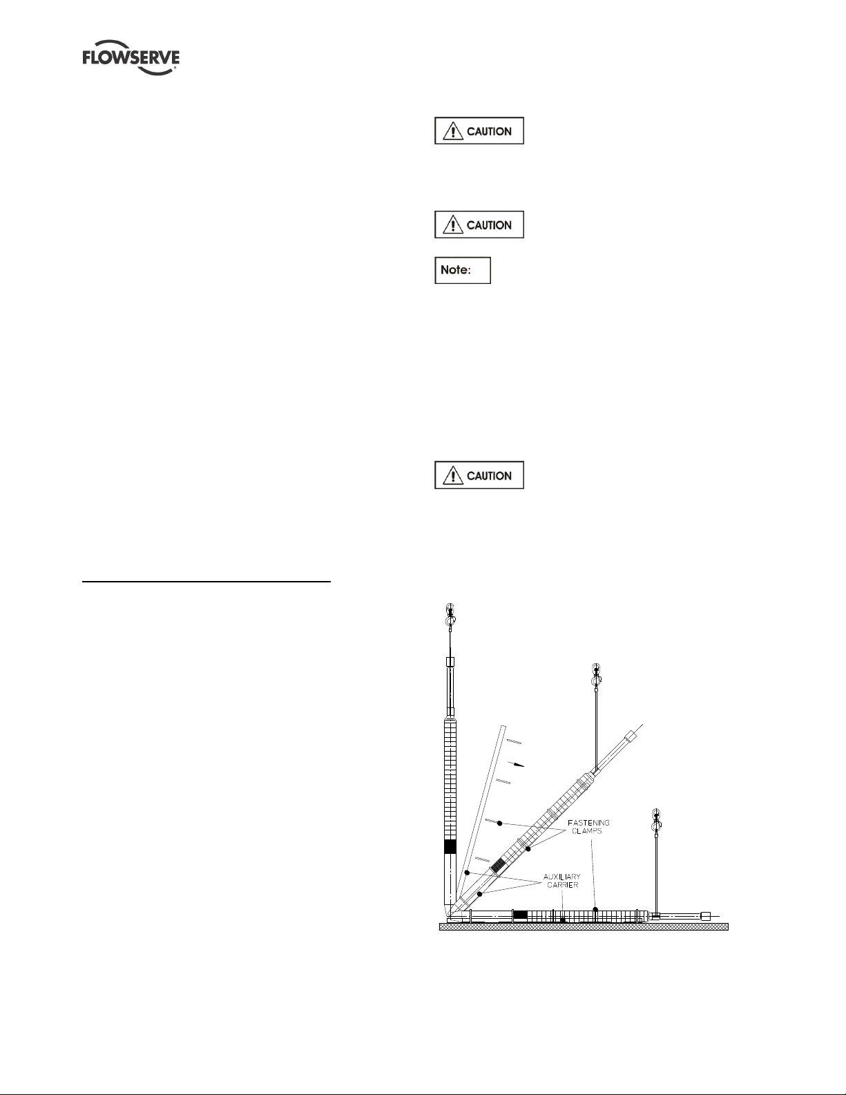
A unit that is shipped on a transport rail due to its
extreme length must be lifted into the vertical position on
this rail (ie an auxiliary carrier) before fitting into the well.
Due to the danger of sagging, pump
units that exceed the permissible length must be
supported by an auxiliary carrier (U or H carrier) when
lifted into the vertical position. This carrier may only be
removed after the pump unit is hanging vertically from
the crane or lifting block. (See figure 2-1.)
Figure 2-1
When assessing the diameter of the unit, use the
smaller size from the pump and motor. This can be
found on the rating plate or the data sheet.
Page 9 of 40 flowserve.com
Page 10
PLEUGER STANDARD USER INSTRUCTIONS ENGLISH 71569293 01-13
Rated diameter
Permissible length
6 in. (152 mm)
3.3 m (10.8 ft)
8 in. (203 mm)
3.5 m (11.5 ft)
10 in. (254 mm)
4.4 m (14.4 ft)
12 in. (305 mm)
4.7 m (15.4 ft)
Table 2-1
Under no circumstances must the
power cables be used for lifting or moving the motor.
2.3 Storage
Store the pump unit vertically in a dry,
well ventilated location. If it cannot be foreseen when
the unit will be installed, the following instructions
must be followed:
2.3.1 General remarks
Submersible pump units need special
storage conditions. For functional reasons some
inner parts (eg the stator and rotor plates) cannot be
produced from corrosion-resistant materials and are
therefore sensitive to any type of air humidity.
All units may basically be stored either in a filled or
unfilled condition; however these two types of storage
require different treatment of the unit.
All units must be stored vertically,
secured appropriately in this position to prevent
tipping over.
The leads of the power cables must
be protected from moisture. Ensure that the power
cables and, if applicable, the signal cables are not
bent during storage.
2.3.2 Requirements for the storage area
The storage area must be well ventilated.
Air humidity should be in a range of 40 to 60 %.
Temperatures:
+50 to -25 °C (+122 to -13 °F) for units with
unfilled motors
+50 to 0 °C (+122 to +32 °F) for units with MX
type motors (water-filled without antifreeze)
+50 to -15 °C (+122 °F to +5 °F) for units with
motors originally filled by the manufacturer
For temperatures down to -15 °C, (+5 °F) see the
guidelines in the instructions for filling submersible
pump motors in section 0, 6.1 Antifreeze.
2.3.3 Storing for up to four weeks
No special arrangements are required.
2.3.4 Storing between one and 24 months
For storage between one and 24 months, it is
recommended that the shaft of the unit be turned at
intervals of approximately 8 weeks. For this it may be
necessary to remove a mounted pressure housing,
including the check valve. On pump units where this is
not possible, the pump and motor must be separated.
If needed, separate instructions should be requested
from the manufacturer.
2.3.5 Storing for over 24 months
If the pump unit is stored for more
than 24 months a complete visual inspection at the
Flowserve manufacturing plant is recommended. An
authorised Flowserve factory representative can also
carry out this inspection.
2.5 Recycling and end of product life
At the end of the service life of the product or its
parts, the relevant materials and parts should be
recycled or disposed of using an environmentally
acceptable method and local requirements.
If the product contains substances that are harmful to
the environment, these should be removed and
disposed of in accordance with current regulations.
This also includes the liquids and or gases that may
be used in the "seal system" or other utilities.
Make sure that hazardous substances are
disposed of safely and that the correct personal
protective equipment is used. The safety
specifications must be in accordance with the current
regulations at all times.
3 DESCRIPTION
3.1 Technical data
Each unit is individually manufactured to the special
requirements of the customer. The specific technical
data regarding head, delivery rate, current requirement,
minimum permissible flow velocity on the external motor
surfaces etc can be found in the data sheet delivered
with the unit or in the order confirmation.
3.2 Delivery contents
Pump unit
These User Instructions
Technical data sheet
Page 10 of 40 flowserve.com
Page 11
PLEUGER STANDARD USER INSTRUCTIONS ENGLISH 71569293 01-13
3.3 General data
3.3.1 Normal operating conditions
Temperature: see data sheet
Sand content: max. 25 mg/l (0.03 oz/fl.oz)
Water velocity along motor surface: see data
sheet
No impurities that could lead to deposits and
blockages within the pump or to deposits on the
motor surface
No water hammer
Maximum 3 minutes operation against closed
slide valve
Refer to section 7.1.2., First
switching on.
Operation within prescribed voltage tolerances
Permissible operational range: 50 to 120 % of the
best efficiency point (BEP)
Correctly selected and adjusted motor protection
Observation of the maximum permissible starting
frequency
If other working conditions are
required please contact Flowserve for advice.
Other uses or applications must be agreed by the
manufacturer.
Power cables and, if applicable, signal cables are
fixed to the riser pipes by means of cable clips.
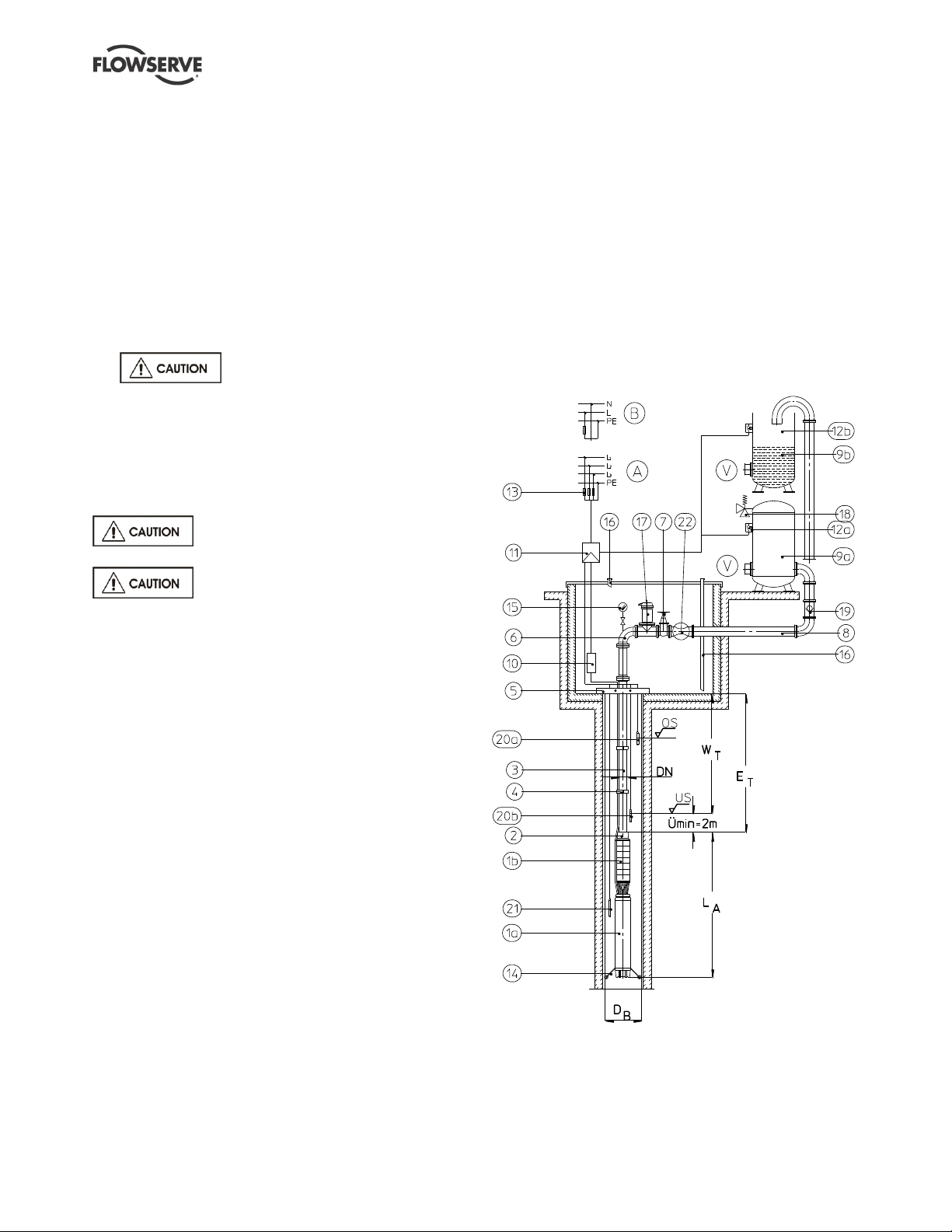
The ideal construction of a water supply system is
shown in figure 3-1. Since this shows a basic
arrangement, the actual layout must be adapted to
local and technical conditions.
The additional listed components are
recommendations for operational safety and the
protection of the pump unit.
Figure 3-1: Water supply system
At higher ambient temperatures
and/or lower flow velocities on the external motor
surfaces, or if there is risk of clogging, special
measures for heat dissipation are required. This
must be checked with the manufacturer by indicating
the ambient conditions. In this case the suitability of
the unit for its planned application must be confirmed
by the manufacturer.
3.4 General description
Submersible-motor pumps are subjected to a thorough
inspection before leaving the factory and are supplied
with operating instructions for fitting, starting and care
that conform to general safety regulations.
Standard submersible-motor pumps are used to
transport cold clean water under normal operating
conditions.
The Pleuger submersible-motor pump has been
developed for installation in wells and as a result has a
distinctive slim design. The Pleuger submersible-motor
pump, because of its various features, can also be used
for other applications with different design modifications.
The submersible motor pump consists of a submersible
motor, a submersible pump and usually a check valve.
The complete pump unit is freely suspended on the
rising main which is supported at the wellhead.
Page 11 of 40 flowserve.com
Page 12
PLEUGER STANDARD USER INSTRUCTIONS ENGLISH 71569293 01-13
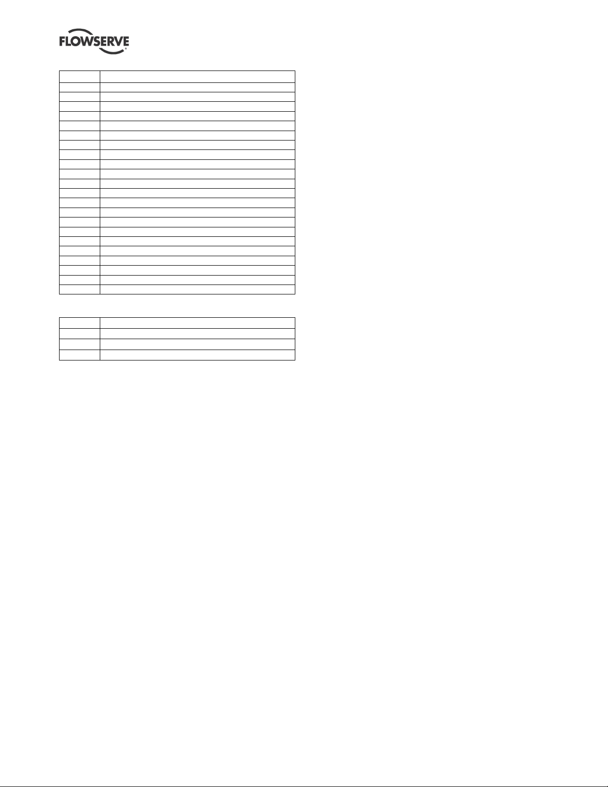
Ref.
Description
1a
Submersible motor
1b
Submersible pump
2
Check valve
3
Riser pipe
4
Cable clips
5
Support clamp
6
Elbow
7
Control valve
8
Delivery pipe
9a
Pressure vessel
9b
High level tank
10
Terminal box for power cable
11
Switchgear or switchboard
12a
Pressure switch
12b
Float switch
13
System fuses
14
Centering device
15
Pressure gauge
16
Well shaft vents
17
Double orifice air valve
18
Safety valve
19
Check valve (optional)
20a
Water level detector, upper
20b
Water level detector, lower
21
Pressure sensor for water level measuring system
22
Flowmeter
As the motor is hermetically sealed and equipped
with a pressure/volume compensating device the
motor filling remains in the motor for the duration of
operation.
On motors larger than 10 in. (254 mm) an impeller
fitted on the motor shaft provides an internal water
circuit for better cooling.
When the unit is operating, the motor filling-water
becomes warm and increases in volume. Excess water
is released through a vent valve/pressure relief valve
located at the top of the motor. After the unit is switched
off, the filling-water cools down and the volume
decreases. A breather diaphragm compensates for the
lower pressure resulting from the decrease in volume.
This arrangement avoids under-pressure in the motor
and the ingress of pumped medium. The change of
volume by varying temperatures continues over the
For safe operation, the following are also
recommended:
entire lifetime of the pump unit.
Although the motor filling-water and the pumped
liquid surrounding the motor will mix if there is
leakage from the seals, the motor remains operative
due to its water-lubricated journal bearings.
Explanations and abbreviations:
DB Well diameter
ET Installation depth
LA Unit length incl. check valve
US Lower operating level = dry running protection
OS Upper operating level (only for automatic operation
Ü Minimum water level above pump outlet
V To the consuming device
WT Minimum (dynamic) water level
(depending on NPSH)
A Connection for a three-phase motor
B Connection for a single-phase motor
3.5 Submersible motor
The so-called “wet” electric motor is a water-filled
three-phase AC squirrel-cage motor with a watertight
winding, which is operating in water and is designed
especially for direct drive of submersible pumps. The
motor filling-water cools the winding and bearings as
well as lubricating the thrust and radial bearings.
The submersible-motor-pump is connected to the
lower end of a riser pipe and submerged in the
pumped medium. The power supply is through water
resistant power cables fastened to the riser pipes with
cable clips.
For operation the motor must be filled with potable
At lower installation depth the motor can, on
customer request, be equipped with a header tank
connected to the motor with a filling and venting
pipeline instead of a pressure compensating system.
Basically, “wet” motors operate maintenance-free
with the ammeter acting as a monitoring device.
The internal temperature of the motor can be
monitored with one or two additional temperature
sensors mounted inside the end coils of the motor
winding. These sensors can trigger a high
temperature warning signal or switch off the motor.
3.5.1 Stator winding
The stator winding consists of winding wire provided
with special insulation.
The power cables are connected to the winding by a
special watertight splice and leave the motor through
stuffing boxes.
The winding and cable connections are tested at high
voltage according VDE 0530 IEC60034-1 immersed
in water, at twice the operating voltage plus 1 000
volts, or a minimum of 2 000 volts.
water. Antifreeze can be added to the potable water
if there is a risk of freezing.
Page 12 of 40 flowserve.com
Page 13

PLEUGER STANDARD USER INSTRUCTIONS ENGLISH 71569293 01-13
3.5.2 Rotor
The rotor winding consists of induction welded copper
bars with short-circuit rings. The rotors are
dynamically balanced and are protected against
corrosion by a protective varnish. The drive shaft end
is made of stainless steel.
3.5.3 Bearings
The "Michel type" axial thrust bearing is located in the
motor base and is designed to handle very high thrust
loads; it is dimensioned so that it can support the
axial thrust of the pump rotating assembly as well as
all hydraulic loads.
The thrust bearing is bi-directional. A fixed counterthrust bearing is also provided. The journal bearings
are slide bearings.
The motor filling liquid lubricates the journals and
thrust bearings.
3.5.4 Mechanical seal
The motor is equipped with a single directional
operating mechanical seal, which can operate in both
directions of rotation.
3.5.5 Starting procedures
The motors can have different operating modes and
starting procedures. Essentially, these are:
Direct-on-line (DOL)
Star-delta starting
Starting via an auto-transformer
Starting via soft-starter. (See also section 3.5.6,
Starting via soft-starter.)
Static-frequency converter operating. (See also
section 3.5.7, Static-frequency converter operating
with submersible motors.)
Single-phase motor - refer to Flowserve
For direct-on-line (DOL), Star-delta starting and starting
via an auto-transformer the electrical data and the
connection diagram for the motor have to be followed.
These are marked in the technical data sheet.
For all other operating modes special procedures
have to be followed that are described in detail below.
3.5.6 Starting via soft-starter
Pleuger submersible motors can be operated via
“soft-start and soft-stop devices”. These instructions
relate to radial and mixed flow pumps.
Axial flow pumps must be referred to the
manufacturer on an individual basis.
A compensation-capacitor must not be installed at the
junction between soft-start and soft-stop devices and
the motor.
Power output reduction is not necessary if the
conditions in section 5.6, Adjustments for soft-starter
and soft stop devices, are observed.
Soft-start ramp up and soft-stop ramp down times
must be clarified with the manufacturer after the
hydraulic system data is finalised.
3.5.7 Static-frequency converter operating with
submersible motors
Technical data needs to be taken from the
specific data sheet.
For submersible motors that are later converted to
static-frequency converter operation, the required
data must be requested from the manufacturer.
3.5.8 Direction of rotation
The direction of rotation depends on the pump type.
Reversing two phases of the power supply will
change the direction of rotation of all three-phase
squirrel-cage motors. (Changing the direction of
rotation of a single-phase motor is not possible.)
3.5.9 Resistance thermometer PT100 (RTD)
Either one or two temperature sensors PT100 (RTD)
are installed with pressure and watertight connections
to a signal cable. As the temperature sensors are
mounted on the winding head they can only be
removed after dismantling the motor.
3.6 Pump and check valve
Radial or semi-axial centrifugal pumps are used as
single or multistage pumps. The pump stages of
pump types NB6 and NB8 are bolted together with
tie-bolts. The pump bowls of all other types of pumps
are bolted together one by one.
The dynamically balanced impellers are fixed to the
pump shaft by means of keys. The pump shaft runs
in journal bearings that are lubricated by the pumped
medium.
Power transmission for 6 in. (152 mm) and 8 in.
(203 mm) motors is via a spline coupling; on all other
motors a keyed coupling is used.
The check valve of pump types NB6 and NB8 is an
integral part of the pump. On all other pump types
the check valve is an independent part, mounted onto
the discharge casing of the pump.
Page 13 of 40 flowserve.com
Page 14

PLEUGER STANDARD USER INSTRUCTIONS ENGLISH 71569293 01-13
4 INSTALLATION
4.1 Hydraulic installation
A typical design for a water supply system is shown
in figure 3-1, Water supply system. As this shows a
basic arrangement, the actual layout must be
adapted to local conditions. (The additional
components listed are recommendations for
operational safety and protection of the pump unit.)
4.2 General advice for installation
The following criteria must be taken into account to
determine the installation position and depth:
Vertical installation in the well above the filter line,
so that an adequate motor cooling flow is
guaranteed along the external motor surface
Sufficient water cover
Static water level at least 2 m (6.6 ft.) above the
pump outlet
A dynamic water level above the suction housing,
taking into account the required NPSH for the
pump. (See pump characteristic curve.)
Flow rate. (See pump characteristic curve.)
Supply conditions of the pumping medium
(depends on the installation conditions)
Regardless of the above, the pump
unit should be installed above the well screen
whenever possible, to avoid foreign matter being
drawn directly into the pump inlet, and also to ensure
that there is sufficient water flowing across the motor
to assist heat transfer. If this is not possible a flow
shroud should be provided to induce the flow of water
over the motor.
Pump units can only be operated with
a completely filled and immersed motor. The liquid
level of the motor must always be checked before
installation and, if necessary, adjusted according to the
information on the data card supplied with the motor.
4.3 Flexible hose riser pipe
If a flexible hose is used instead of
steel pipes, these will twist against the direction of
rotation of the motor when it is switched on,
depending on the locked rotor torque of the motor. In
this case, the power cable (and, if provided, the
signal cable) fastened to the riser hose would also
twist and tighten. To prevent the cables being pulled
out of their junction boxes, they should not be laid
parallel to the riser hose but wound around it in the
opposite direction to the rotation of the motor. The
number of turns required will depend on the length
and stiffness of the riser hose line and the locked
rotor torque of the motor. The exact operating
characteristics will need to be requested from the
hose manufacturer.
4.4 Centralizers
When pump units are installed in narrow wells the
risers, whether steel pipes or hose lines, will need to
be centralized to prevent them from touching the wall
of the well which could cause damage to any cables
fastened to them.
4.5 Checks before installation
Before beginning installation, check the
dependability of auxiliary equipment, particularly
hoists, as well as comparing the information on the
data sheet with that on the rating plate on the motor.
Ensure that the line voltage (measured between two
phases) is equal to the motor voltage shown on the
rating plate.
The maximum permissible voltage fluctuation can be
seen in the data sheet. Greater voltage and frequency
fluctuations must be stated in the order and confirmed by
the factory. In case of doubt, contact Flowserve or the
nearest factory representative before starting up the unit.
Before installing, the insulating resistance of the
motor must be measured as shown in section 8.3,
Measuring insulation.
Ensure that the well diameter is large enough down
to the installation depth, so that the pump unit can be
installed without difficulties. If the riser connections
are made of pipes with flanges, these must have cut
outs for the cable if the well diameter is narrow.
When lowering the unit, ensure the power cable is
neither squeezed nor scraped. To protect the power
cables, we recommend that the well head is lined
with a rubber sheet at the entry point of the power/
signal cable into the well pipe and it is fed into the
well shaft using a cable roller. (See figure 4-1.)
During lowering, the unit must always hang freely and
must not become wedged in the well shaft. Always
ensure that the pump can be rotated freely. If
needed, attach a cable clip every 3 m (approx. 10 ft.)
of pipe length.
For especially narrow and deep wells, the insulating
measurements shown in section 8.3, Measuring
insulation, should be repeated to determine possible
damage to the power cables in time.
Page 14 of 40 flowserve.com
Page 15

PLEUGER STANDARD USER INSTRUCTIONS ENGLISH 71569293 01-13
g) When this has been completed lift the unit
sufficiently to enable the supporting clamp to be
removed.
Do not allow the pipe to be lowered or to
slip whilst carrying out this operation. This could
result in damage to hands and in extreme cases
loss of fingers.
h) Install the remaining riser pipes as described
from point b) to e).
i) Finally mount the wellhead support plate onto the
last length of riser pipe. Feed the power cables
and, if necessary, the control lines and/or
instrument leads through the corresponding holes
in the wellhead support plate and connect them
to the junction box or control panel.
4.8 Riser pipe with pipe socket
(Reference “B” in figure 4-1.)
a) Connect a lifting clamp underneath the pipe
socket of the screwed riser pipe and lift the
complete pump unit with a suitable hoist.
b) Lower the pump unit into the well as far as the
installation clamp mounted underneath the socket
of the riser pipe.
c) Lower the unit and rest it on the well rim flange.
Figure 4-1
4.6 Installation of pre-assembled pump
units
Mount the first length of pipe, which should not be
longer than 1 m (39 in.), onto the assembled pump unit.
Fasten the power cables, control lines and instrument
leads (if any) with cable clips onto the pipe.
4.7 Riser pipes with flange connections
(Reference “A” in figure 4-1.)
a) Mount a "lifting dolly” to the riser pipe flange, and
hang the complete unit on a suitable hoist.
b) Lower the pump unit into the well, allowing
sufficient pipe to protrude above the well to
enable the installation clamp to be mounted onto
the riser pipe.
c) Continue to lower the unit until the installation
clamp rests on the well rim flange.
d) Remove the lifting dolly, and attach it to the next
riser pipe to be installed.
e) Fasten the power cable, control lines and
instrument leads (if any) with cable clips to the
riser pipe.
f) Lift the next pipe to be installed into a vertical
position and bolt it to the pipe resting on the well
rim flange.
Do not let the pump unit slip
through the installation clamp.
j) Remove the lifting clamp and attach it to the next
riser pipe and connect this to the pipe already
installed.
k) Fasten the power cables and, if necessary, the
control lines and/or instrument leads with cable
clips onto the riser pipe.
l) Lift the unit and remove the resting supporting
clamp.
m) Install the remaining riser pipes as described
from point b) to f).
n) Finally mount the wellhead support plate onto the
last riser pipe. Feed the power cables and, if
necessary, the control lines and/or instrument
leads through the corresponding holes in the
wellhead support plate and connect them to the
junction box or control panel.
4.9 Assembly of submersible motor
pumps before installation
Submersible motor pump units that are delivered in
sub-assemblies have to be assembled during or
before installation. For assembly of these submersible
motor pump units the specific installation instructions
have to be requested from the manufacturer if they
have not been delivered with the unit.
Page 15 of 40 flowserve.com
Page 16

PLEUGER STANDARD USER INSTRUCTIONS ENGLISH 71569293 01-13
5 ELECTRICAL CONNECTIONS
5.1 Motor
All work on the electrical system must
be performed by a qualified Electrician in accordance
with relevant local, national and international
regulations.
The connection diagrams in the following sections
show the basic structure of the connection
possibilities and the line arrangement of the mains
and motor power cable.
Detailed information about the connection of
motors and, if necessary, of control and monitoring
devices can be taken from the appropriate circuit
diagrams from the control panel manufacturer.
To ensure a good connection with the least possible
contact resistance when connecting the power lines,
the conductor ends should not be tin-plated. If the
conductor ends are tin-plated, these should be
removed. The exposed fine-strand wires must be
connected to the electrical supply with suitable
terminal screws or by crimping or soldered cable lugs.
5.1.1 Labelling of conductor ends and rotation
direction of three-phase motors
The conductor ends of the power cables are labelled
so that all three-phase motors rotate clockwise (seen
from the coupling ends and towards the shaft) when
connected to a clockwise rotating system according
to figure 5-1 to 5-5.
Counter clockwise rotation occurs if two phases of
the main connection are transposed from that shown
in the clockwise connection diagrams (compare
figures 5-7 to 5-11).
Power supply cables with round or flat cross-sections
are connected to the motor. Depending on power
consumption or if the installation circumstances are
restricted then several single core cables can be
used.
5.1.2 Single-phase motors
The direction of rotation of single-phase motors
(alternating current motors) is pre-set by the
manufacturer and cannot be changed. The rotation
direction pre-set by the manufacturer can be seen in
the data sheet. Connection can only be made using
the switching device accompanying the motor for
which the labelling of the leads can be found in figure
5-6 or 5-12.
5.1.3 Motors with one power cable
One four lead power cable is connected to the motor
for direct-on-line starting, also auto transformer
starting, starting via soft-start and soft-running-out
devices as well as for static-frequency operating
(compare figures 5-1 and 5-7), if the current load of
the leads allow it.
5.1.4 Motors with two power supply cables,
parallel connection
See attachment TI 01-04 E for the
interim solution for motors with old and new coloured
power supply cables until 01 April 2006.
When the rated current of a motor cannot be supplied
by one cable it is equipped with two parallel cables.
The connections for a motor with two power cables,
with parallel connection, as well as the colour and
letter labelling of the conductor ends, is shown in
figure 5-2 or 5-8.
5.1.5 Motors with two power supply cables,
parallel connection (open delta-connection)
See attachment TI 01-04 E for the
interim solution for motors with old and new coloured
power supply cables until 01 April 2006.
For motors with star-delta starting (figure 5-3 or 5-9),
motors whose star connection (figure 5-4 or 5-10) and
or delta connection (figure 5-5 or 5-11) is in the control
panel, as well as for motors provided with two different
voltages, two three-lead and or one three- and one
four-lead power cables are connected to the motor.
5.2 Protective measures against shockhazard voltage
Protective measures against shock-hazard voltages
must be taken according to IEC regulations and the
local electricity supply company ordinances.
According to IEC-regulations the protective conductor
must be connected directly to the motor on new
systems. This also applies when the unit is installed
in an inaccessible well.
If there is no earth lead on the motor, a
separate earth lead must be connected to the motor
using the earth screw supplied. This is labelled with a
symbol.
Page 16 of 40 flowserve.com
Page 17

PLEUGER STANDARD USER INSTRUCTIONS ENGLISH 71569293 01-13
IA
t
L
100 mm (4 in.)
150 mm (6 in.) or larger
1.05 x IE
> 2 hours
cold
1.,20 x IE
< 2 hours
warm
5 x IE
6 x IE
10seconds
cold
5.3 Motor protection
To protect the motor against current overload, a
thermal overload relay must be provided. The
tripping time of the relay should have temperature
compensation to allow for variations in ambient
temperature. It should also have accelerated tripping
under single-phase conditions.
Trip reset should only be possible manually.
The setting of the thermal overload relay must be
chosen according to the data sheet provided with the
pump.
For star-delta motor starters, it is important that the
protection relay is in the motor line (see figure 5-3 or
5-9). The adjusted current level will then be 58 % of
the operational current. If the protection relay has
been installed in the power line in exception to this
rule, the adjusted current is the same as the
operational current.
Table 5-1; Overload relay tripping characteristic
5.4 Short circuit protection
To prevent a short circuit in the power cable and the
motor, safety precautions must be taken according to
local regulations.
Guide values for safety fuse sizes can be found in the
data sheet.
IA = Release current
IE = operational current (rated current)
t = Delay time until release
L = Operational temperature before overload
The adjustment of the motor protection relay
(thermally delayed over current release) must be set
according to the value given in the data sheet.
The value given in the data sheet is a standard value
for the operating point. If the actual operational
current in the operating point of the pump is less than
this given value, the motor protection must be
adjusted lower so that there is effective protection
and malfunctions can be indicated in time.
The motor protection adjustment must
never be set higher than the highest permissible
value given in the data sheet. Testing the correct
operation of a motor protection switch by deliberate
single phasing is not permitted!
Page 17 of 40 flowserve.com
Page 18

PLEUGER STANDARD USER INSTRUCTIONS ENGLISH 71569293 01-13
Old
New
U
=
black
V = light blue
brown
W = brown
grey
PE = green/yellow
Old
New
U1/U2 = black
V1/V2 = light blue
brown
W1/W2 = brown
grey
PE = green/yellow
Old
New
U1/U2 = black
V1/V2
=
light blue
brown
W1/W2 = brown
grey
PE = green/yellow
Old
New
U
=
black
V = light blue
brown
W = brown
grey
PE = green/yellow
Old
New
U1/U2 = black
V1/V2 = light blue
brown
W1/W2 = brown
grey
PE = green/yellow
V = light blue
UV = brown
Z
=
black
PE = green/yellow
5.5 Motor connection diagrams
5.5.1 Clockwise rotation
Figure 5-1: Direct-on-line-starting
- one power supply cable
Figure 5-3: Star-delta-stating
Figure 5-5: Direct-on-line-starting delta-connection in control panel
Figure 5-2: Direct-on-line-starting
- two power supply cables
Page 18 of 40 flowserve.com
Figure 5-4: Direct-on-line-starting
- star-connection in control panel
Figure 5-6: Single-phase motor
Page 19

PLEUGER STANDARD USER INSTRUCTIONS ENGLISH 71569293 01-13
Old
New
U
=
black
V = light blue
brown
W = brown
grey
PE = green/yellow
Old
New
U1/U2 = black
V1/V2 = light blue
brown
W1/W2 = brown
grey
PE = green/yellow
Old
New
U1/U2 = black
V1/V2 = light blue
brown
W1/W2 = brown
grey
PE = green/yellow
Old
New
U
=
black
V = light blue
brown
W = brown
grey
PE = green/yellow
Old
New
U1/U2 = black
V1/V2 = light blue
brown
W1/W2 = brown
grey
PE = green/yellow
V = light blue
UV = brown
Z
=
black
PE = green/yellow
5.5.2 Counter-clockwise rotation
Figure 5-7: Direct-on-line-starting
- one power supply cable
Figure 5-9: Star-delta-stating
Figure 5-11: Direct-on-line-starting
- delta-connection in control panel
Figure 5-8: Direct-on-line-starting
- two power supply cables
Page 19 of 40 flowserve.com
Figure 5-10: Direct-on-line-starting
- star-connection in control panel
Figure 5-12: Single-phase motor
Page 20

PLEUGER STANDARD USER INSTRUCTIONS ENGLISH 71569293 01-13
Motor type
Minimum permitted current limit as
% of motor rated current
M6
250
M8 up to VNI 14
300
MI 16
350
> MI 16
On request
Motor type
Maximum starts and run-outs per hour
M6
8
M8 to MI16
6
> MI16
On request
Ambient temperature
Minimum flow velocity
30 °C (86 °F)
0.5 m/s (1.64 ft/sec)
20 °C (68 °F)
0.2 m/s (0.66 ft/sec)
5.6 Adjustments for soft-starter and soft
stop devices
5.6.1 Minimum permissible current limits
Table 5-2
5.6.2 Minimum start-up voltage
On adjustable devices do not adjust the start-up
voltage lower than 55 % of the rated voltage.
5.6.3 Permissible ramp-up time
To avoid thermal overload and damage to the bearings
DO NOT adjust the ramp-up time above 5 seconds.
On units with a dual ramp-time function or pump
function the sum of the dual ramp-time must not
exceed 5 seconds. Any other ramp-up time above 5
seconds must be referred to Flowserve for approval.
Should external guidelines state differing values than
those stated above, the above values must take
precedent. This function should not be used for
speed adjustment of the motor.
5.6.4 Permissible ramp-down time
The maximum ramp-down time must not exceed 20
seconds.
On units with a dual ramp-time-function or pumpfunction the total amount of ramp-time must not exceed
20 seconds. The amount of running-out voltage in this
case must not be less than 45 % of the rated voltage.
Any other ramp-down time above 20 seconds must
be referred to Flowserve for approval.
Should external guidelines state differing values than
those stated above, the above values must take
precedent. This function should not be used for
speed adjustment of the motor.
5.6.5 Starting frequency
Table 5-3
The number of starts per hour should be spread
equally over the hour.
In addition, pay attention to the starting frequency of
the soft-start device, which could possibly be less.
5.6.6 Soft starter current limit
To have sufficient reserve for any required additional
acceleration torque, the choice of the soft-start device
must be carefully considered to ensure that the
starter can deliver at least four times the motor rated
current.
5.7 Operation of submersible motors
with static frequency converter
5.7.1 General
Motors for operation with a static frequency converter
are specially designed. Major operating criteria are
the temperature rise of the motor depending on
additional losses and the higher voltage stress on
static frequency converter operation.
5.7.2 Cooling
Generally, the flow velocity along the motor must be
guaranteed for the nominal condition according to
table 5-4.
Table 5-4
5.7.3 Starting conditions
The minimum frequency of 10 Hz must be reached
within 0.5 seconds.
5.7.4 Permissible operating frequency range
The acceptable operating frequency is from a
minimum of 10 Hz up to a maximum of the nominal
frequency. (Refer to the data card.)
In this case the allowable pumping
capacity range must be observed. (See section
3.3.1, Normal operating conditions.) This may result
in a minimum operating frequency above 10 Hz.
5.7.5 Maximum voltage stress
The rise in voltage should be less than 500 V/µs and
be limited to 1.5 UN.
5.7.6 Power cable
Shielded power cables should be used at the top of the
borehole/well. The cables between the submersible
motor and the surface connections must be installed in
an adequate Cu-mesh shield that is extensively earthed
on both sides.
Page 20 of 40 flowserve.com
Page 21

PLEUGER STANDARD USER INSTRUCTIONS ENGLISH 71569293 01-13
Motor filling
type
“FSM1”
% volume
Water
% volume
Protection
down to:
MF 15 *
35
65
- 15 °C (5 °F)
MF 20
40
60
- 20 °C (-4 °F)
MF 25
45
55
- 25 °C (-13 °F)
MF 30
50
50
- 30 °C (-22 °F)
Filled
Unfilled
M 6
MX6
M 8
MX8
MI 10
MIX10
VNI 12
VNI 14
MI 16
MI 19
VNI 22
MI 26
VNI 30
Any power supply cables must be sized for this higher
voltage, depending on the static frequency converter.
Follow the instructions of the manufacturer of
the frequency converter regarding the maximum
length of the power cables.
The signal cables for temperature sensors should be
installed at a distance as far as possible from the high
voltage power cables.
5.8 Resistance sensor PT100 (RTD)
Figure 5-13: Standard connection diagram for one
PT100 (RTD)
Figure 5-14: Standard connection diagram for two
PT100 (RTD)
regions only) filled only with drinking water. For
specifically ordered units filled only with drinking
water the client is responsible for ensuring that
storage and use do not permit freezing.
This standard concentration is always the same
unless the customer or operator expressly states a
different preference.
For units supplied with a header tank, the fitting of an
audible or visual alarm is recommended to monitor the
filling level of the motor in case of leakage. This can be,
for example, a float switch installed in the overhead tank.
6.1 Antifreeze
Only MF-type motor filling should be
used as antifreeze.
6.1.1 Motor filling - MF-type
MF-type motor filling is a liquid consisting of “FSM1”
antifreeze and water. “FSM1” antifreeze is
manufactured based on propylene-glycol. The mixing
ratios must be prepared according to table 6-1.
Table 6-1
5.8.1 Adjustment of motor temperature
protection relay
The adjustment of the motor temperature protection
relays depends on the rated output and the flow
conditions along the motor surface. The permissible
temperatures are shown on the enclosed data sheet
as far as the motor is equipped with Pt100 resistance
sensors. Examples of values are:
At 60 °C (140 °F) high temperature: early warning
At 65 °C (149 °F) high temperature: motor shut down
6 MOTOR FILLING
The motor must be filled with clean, oil-free and
grease-free drinking water, to which antifreeze can be
added if there is a risk of freezing.
Never use distilled water.
All motors delivered ready-filled by the manufacturer
have antifreeze added which gives protection down to
-15 °C (5 °F) unless specifically ordered (certain
* Standard filling
6.1.2 As-delivered state
These instructions apply to the motor types listed in
table 6-2. They are also applicable to Polder pumps,
prefixed with a “P”. As a general rule, all motors are
delivered as shown in table 6-2.
Table 6-2
Every motor carries a label indicating its state of filling
on delivery.
Yellow label = filled
Green label = unfilled
In all cases the state of filling stated on the label must
be observed.
Page 21 of 40 flowserve.com
Page 22

PLEUGER STANDARD USER INSTRUCTIONS ENGLISH 71569293 01-13
Motor type
Filling quantity
litres
US gal
M 6
MX6
4 to 4.5
1 to 1.2
M 8
MX8
8.5 to 9
2.2 to 2.4
MI 10
MIX10
15 4 VNI 12
35 to 40
9 to 11
VNI 14
53 to 60
14 to 16
MI 16
75
20
MI 19
150
40
VNI 22
200
53
MI 26
300
80
VNI 30
360
95
Designation
Diagram
Size
Part. no.
Vent valve
< 0.3 bar
B6523
> 0.8 bar
Filling valve
R³/8 in.
B6514
R³/4 in.
Screw plug
R³/8 in.
6780
R³/4 in.
M16 x 1.5
Filling screw
- -
- -
Protection cap
- -
0236
Filling nipple
M10
(2)
M16
6.1.3 Topping up of pre-filled motors
Topping up of pre-filled motors can be done with
potable water without antifreeze if the quantity of
topping up liquid is relatively small (1-2 %).
6.2 Type of use
The filling of motors depends not only on the motor
size and type, but also on the type of use. The
standard uses are described below.
6.2.1 Vertical installation
Normal design
Normal design in cooling/suction shroud
Normal design in closed shroud
Polder pump
Cavern pump
6.2.2 Horizontal installation
Normal design
Normal design in closed shroud
Pumping station
Heeling pump
6.3 Filling quantities
The filling quantities stated in table 6-3 are
approximate and may vary slightly due to differing
lamination lengths.
Table 6-3
Table 6-4: Accessories and hardware
6.5 General information about filling
The 6.5 General information about filling in this
section applies to all motor types, unless stated
otherwise in the individual descriptions. If units that
require filling are not mentioned in these instructions,
special instructions must be requested from the
manufacturer.
6.5.1 Filling pressure
6.4 Accessories and hardware for filling
and topping up
Motors must be filled and topped up as shown in the
descriptions and accompanying diagrams from
section 6-6, Filling instructions, onwards.
The various components referred to in the individual
descriptions and diagrams are summarized here for
the sake of simplicity and shown in table 6-4,
Accessories and hardware.
To avoid damage to the shaft seal and
pressure equalization system, the filling pressure at
the inlet of the screw connection must not exceed the
maximum pressure stated below when connected to
a water supply such as a household tap:
Motors with the designation MI: ..... 1.0 bar
All other motors: ............................. 0.5 bar
6.5.2 Duration of filling
Even though the filling liquid being filled overflows
from the venting pipe, there may still be residual air in
the motor. It is therefore recommended to repeat the
filling process after approx. 5 minutes to ensure that
all cavities are filled with liquid and all air bubbles
have escaped from the motor.
6.5.3 Filling valve, filling nipple, filling aids
After filling the motor the hose of the filling pump can
be removed from the nipple and the nipple can be
screwed out from the filling valve without any risk that
the liquid escapes from the motor as the filling valve
is designed to prevent any leakage.
Page 22 of 40 flowserve.com
Page 23

PLEUGER STANDARD USER INSTRUCTIONS ENGLISH 71569293 01-13
Motor type
Suction
shroud
Filling
valve
Screw plug
Filling
accessory
* Filling nipple
Thread size -
hose diameter
M6
MX6
without
without
screw plug
funnel
with 3/8 in
* M10 - Ø15/19
pump
M8
MX8
without
without
screw plug
funnel
with 3/8 in
* M10 - Ø15/19
pump
MI10
MIX10
without
without
screw plug
funnel
with 3/8 in.
* M10 - Ø15/19
pump
VNI12
¾ in.
* M16 - Ø15/19
pump
VNI14
MI16
MI19
VNI22
MI26
VNI30
Item no.
Description
Quantity
B6523
Vent valve
1
6780
Screw plug
1
4510
Sealing ring
3
The connection apertures for filling the motors vary
according to the motor type and model. Table 6-5
shows the filling aids which are required for filling or
topping up motors.
Table 6-5
6.5.4 Filling pump
The filling pump is only suitable for filling motors that
are equipped with a filling valve [B6514] in the bottom
bearing or thrust bearing housing.
A filling valve [B6514] can be fitted in place of a
screw plug [6780], however the valve cannot be
screwed out again after the motor has been filled; it
must remain fitted. Replacing the screw plug does
not affect the functioning of the motor.
6.5.5 Sealing cap
The sealing cap [0236] must only be fitted for
transportation and storage.
The sealing cap [0236) must always
be removed when the motor is put into service.
6.5.6 Filling liquid
If a motor has to be filled or topped up with a mixture
of water and antifreeze, this must be prepared in a
clean container before filling the motor.
6.5.7 Header tank (optional)
If a header tank is installed it is recommended that it
is fitted with a float switch for automatic monitoring of
the liquid. This ensures that the motor is always full.
The header tank must be not more than 5 m (16.4 ft),
corresponding to 0.5 bar (7.25 psi), above the lowest
level of the pumped liquid, or the motor, to ensure
sealing of the motor. If a greater height cannot be
avoided, the manufacturer must be consulted.
6.5.7.1 Pipes
When installing a header tank, pipes with a nominal
size of at least 13 mm (½ in.) must be used between
tank and motor for venting and filling the motor.
To ensure the motor is properly filled, the installation
of a drain valve in the return pipe below the tank
bottom is recommended. This valve must remain
open during filling and topping up until the liquid
escaping from it is free of bubbles.
The drain valve must never be fitted
so that it can shut off the return pipe.
6.5.8 Vent valves
Vent valves are available with different pressure
ratings. The appropriate valve is selected according
to the purpose for which the submersible motors are
to be used. So that filling with liquid does not have to
take place against the opening pressure of the vent
valve, it can be screwed out for the duration of filling if
the installation position allows this.
It is essential that the vent valve is
screwed in again after filling.
6.5.9 Accessory pack “Z”
For submersible motors installed horizontally, and in
some cases vertically, the vent valves and screw
plugs must be exchanged or replaced on site. The
parts required for this are supplied in accessory pack
“Z”, as shown in table 6-6, with the respective motor.
Relevant instructions are given in the filling details for
the particular motor type and for the specific
application.
Table 6-6: Accessory pack “Z”
6.6 Filling instructions
The procedures for filling and topping up submersible
motors described below depend on the method of
installation and the type of motor used. As a rule it is
not possible to use all installation methods for all
motor types, and for this reason the following table
shows which installation methods are used as
standard for the different motors. For special cases
not mentioned here, the manufacturer must be
consulted.
The relevant section for motor filling must be taken from
the data sheet belonging to the corresponding unit.
Page 23 of 40 flowserve.com
Page 24

PLEUGER STANDARD USER INSTRUCTIONS ENGLISH 71569293 01-13
Motor
type
Section numbers
6.6.1
6.6.2
6.6.3
6.6.4
6.6.5
6.6.6
6.6.7
6.6.8
6.6.9
6.6.10
6.6.11
M6
•
O
•
•
O
O
•
MP6
O
•
O
O
MX6
• O •
•
O
O
•
M8
•
O
•
•
O
O
•
MP8
O
•
O
O
MX8
• O •
•
O
O
•
MI10
•
O
•
•
O
O
•
MIP10
O
•
O
O
MIX10
• O •
•
O
O
•
VNI12
• O •
•
O
O
•
VNI14
• O •
•
•
O
O
•
MI16
• O •
•
•
O
O
•
MI19
•
O
VNI22
•
O
MI26
•
O
VNI30
•
O
•
= standard
O = optional
Not currently
scheduled
Figure 6-1
In special cases the filling instructions must be
requested from the manufacturer.
Table 6-7
The following instructions are only relevant for filling
and topping up before the first installation, for motors
without a header tank. Before installation ensure that
the motors do not have any leaks.
For installations with a header tank, the liquid level
must be monitored. Installation of an automatic level
control is recommended.
6.6.1 Filling and topping up with a funnel
(See figure 6-1.)
a) Position the motor vertically and prevent the unit
from falling over.
b) Remove the cap [0236] of the vent valve [B6523]
with a screwdriver or similar tool.
c) Screw out the vent valve [B6523] with a ring
wrench or socket wrench (size 17).
Handle seal ring [4510.10] with
care.
d) Fit together the two-part funnel [1], and insert it
into the threaded hole of the removed vent valve.
e) Fill or top up until liquid escapes from the vent
opening.
f) Screw the vent valve [B6523] back in with its seal
ring [4510.10].
6.6.2 Filling and topping up with filling pump
(See figure 6-2.)
a) Position the motor vertically and prevent the unit
from falling over.
b) Remove the cap [0236] of the vent valve [B6523]
with a screwdriver or similar tool.
The cap [0236] is only used for
protection during transportation and must always
be removed before installation.
c) Screw out the inner screw plug [0168] of the
filling valve [B6514].
The cap [0236] is only used for
protection during transportation and must always
be removed before installation.
Page 24 of 40 flowserve.com
d) Screw the filling nipple supplied [2] into the screw
plug threaded hole.
Handle seal ring [4510] with care.
Page 25

PLEUGER STANDARD USER INSTRUCTIONS ENGLISH 71569293 01-13
Figure 6-3
d) Fill the motor before installation using a funnel [4]
The connections of the filling nipple [2]
are different sizes. Fit the relevant filling nipple
[M10 or M16] into the threaded hole.
e) Fit the hose end of the filling pump over the
nipple [2] and place the pump into a container [3]
filled with the filling liquid.
f) Fill the motor until the liquid escapes from the
vent valve [B6523] with no bubbles.
g) Pull the pump hose off the nipple and screw out
the nipple.
h) Refit the screw plug [0168] into the filling valve
[B6514] together with the seal ring [4510].
into filling pipe “F” until the liquid escapes with no
bubbles from vent pipe “V”.
e) Install the motor and fill the connected filling and
venting pipes during installation. (If using
multiple pipes it is advisable to fill the subsequent
pipes with liquid immediately after fitting to test
the connections for leakage.)
f) After installing the header tank [1] and connecting
the pipes to it, fill the tank with liquid up to the
mark indicated. When filling the tank, ensure that
no liquid enters the vent pipe “V”.
Figure 6-2
6.6.3 Motors with header tank for vertical
installation
(See figure 6-3.)
Motors for this type of installation are
specially equipped.
a) Position the motor vertically and prevent the unit
from falling over.
b) Screw out the adapter with vent valve [2] from the
vent pipe “V”.
c) Remove the adapter and plug [3] from the filing
pipe “F”.
Page 25 of 40 flowserve.com
6.6.4 Filling and topping up units with cooling/
suction shroud
(See figure 6-4.)
a) Position the unit vertically and prevent the unit
from falling over.
b) Remove the inner screw plug [0168] of the filling
valve [B6514].
Handle seal ring [4510] with care.
c) Screw the filling nipple into the threaded hole
from which the screw plug [0168] was removed.
The hose connections of the filling
nipples [2] are different sizes. The correct one for
the thread size (M10 or M16) and the pump hose
must be fitted.
Page 26

PLEUGER STANDARD USER INSTRUCTIONS ENGLISH 71569293 01-13
d) Fit the hose end of the filling pump over the filling
nipple and place the pump in a container [3] filled
with liquid.
e) Fill the motor until the liquid escaping from the
vent valve (B 6523) contains no bubbles. (As the
area in which the vent valve [B6523] is fitted is
not accessible to inspection, a relatively large
amount of liquid should be allowed to escape to
ensure that the motor is completely full.)
f) Pull the filling pump hose off the filling nipple [2]
and screw out the filling nipple.
g) Refit the screw plug [0168] into the filling valve
[B6514] together with its seal ring [4510].
Figure 6-4
6.6.5 Filling and topping up units with shrouds
for vertical installation
(See figure 6-5.)
This section is also valid for horizontal
installation of 6 in. (150 mm), 8 in. (200 mm) and
10 in. (250 mm) units with shrouds.
a) Position the unit vertically and prevent it from
falling over.
b) Remove the screw plug [5] from the filling
connection [1].
Handle seal ring [3] with care.
When undoing screw plug [5] hold the filling
connection [1] securely with a wrench (size 27)
so that the pipe or hose fitted inside the shroud is
not twisted.
Figure 6-5
c) Screw the M 10 filling nipple supplied [2] into the
threaded hole of the screw plug.
d) Fit the hose end of the filling pump over the filling
nipple [2] and place the pump in a container filled
with liquid [4].
e) Fill the motor until the liquid escaping from the vent
valve (B6523) contains no bubbles. As the area in
which the vent valve [B6523] is fitted is not
accessible to inspection, a relatively large quantity
of liquid should be allowed to escape from it to
ensure that the motor is completely full. If the unit is
fitted with a foot valve [6] it must be removed to
allow the overflow of liquid to be monitored.
f) Pull the filling pump hose off the filling nipple [5]
and screw out the filling nipple.
g) Refit the screw plug [5] into the filling connection
[1] together with its seal ring [3].
When tightening the screw plug
[5] hold the filling connection [1] securely with a
wrench [size 27] so that the pipe or hose fitted
inside the shroud is not twisted.
Page 26 of 40 flowserve.com
Page 27

PLEUGER STANDARD USER INSTRUCTIONS ENGLISH 71569293 01-13
6.6.6 MP6 Polder motors
(See figure 6-6.)
a) Position the unit with the motor vertical and
prevent the unit from falling over.
b) Screw off the cap nuts including plug [1] from the
filling and return pipes [A].
c) To fill or top up the motor, insert a funnel [5] into
one of the two pipes and pour in the liquid until it
escape with no bubbles from the other pipe.
Filling and vent pipes of this type of
polder motors do not generally have identifying
markings, therefore either pipe can be selected.
d) To enable the filling of the motor with a pump [3]
a filling valve [9701.259/7] together with an
adapter piece [1078.615/2] must be fitted onto
one of the pipes. For the supplementary
installation the following parts (not supplied as
standard) are required:
1 x adapter piece TLN 1078.615/2
1 x filling valve TLN 9701.259/7
1 x filling nipple [2] TLN 9452.558/2
1 x filling pump [3] with filling hose
Alternatively, large motors can be filled with a
filling pump via a pressurised water connection.
The filling pressure at the inlet of
the screw connection must not exceed 0.5 bar
(7.25 psi) maximum when connected to a water
supply such as a household tap.
e) After filling, unscrew the filling valve and the
adapter piece and screw the cap nuts including
plugs [1] back onto the filling and return pipe.
6.6.7 Filling and topping up MP 8/MIP 10 motors
for polder pumps using a filling pump (with filling
and venting pipe on top)
(See figure 6-7.)
a) Position the unit with the motor vertical and
prevent the unit falling over.
b) Screw off the cap nuts with plug [1a] (thread size
M12x1.5) from the venting pipe “V” and [1b]
(thread size M16x1.5) from the filling pipe “F”.
c) Screw in a filling valve [9701.259/7] together with
an adapter piece [1078.615/2] onto the thread for
the cap nut [1b].
Figure 6-6
Page 27 of 40 flowserve.com
Figure 6-7
Page 28

PLEUGER STANDARD USER INSTRUCTIONS ENGLISH 71569293 01-13
Figure 6-8
d) Unscrew the plug screw [0168] from the filling
valve [9701.259/7] and fit a filling nipple [2] into
the threaded hole.
e) Using the filling pump [3] fill the motor until the
liquid escapes from the return pipe “V” with no
bubbles.
f) After filling, unscrew the adapter piece and the
filling valve and screw the cap nut and plug
screws back onto the filling and return pipes. For
the supplementary installation the following parts
(not supplied as standard) are required:
1 x adapter piece TLN 1078.615/2
1 x filling valve TLN 9701.259/7
1 x filling nipple [2] TLN 9452.558/2
1 x filling pump [3] with filling hose
Large motors can be filled via a pressurised
water connection. For this a hose can be pulled
onto the filling nipple [2].
The filling pressure at the inlet of
the screw connection must not exceed 0.5 bar
(7.25 psi) maximum when connected to a water
supply such as a household tap.
6.6.8 Filling motors with external pressure
equalization (outside compensation pipe)
(See figure 6-8.)
a) Position the unit with the motor vertical and
prevent the unit from falling over.
b) Remove the vent screw [1].
c) Remove the inner screw plug [0168] of the filling
valve [B 6514].
j) Remove the inner screw plug [0168] of the filling
valve [4].
Handle seal ring [4510] with care.
k) Screw the supplied filling nipple [2] into the
threaded hole from which the screw plug [0168]
was removed, and fill the expansion pipe [5] until
the liquid escapes from the top end "U".
l) Screw the filling nipple out of the filling valve [4]
and refit the screw plug [0168] into the filling
valve together with the seal ring [4510].
Handle seal ring [4510] with care.
d) Screw the filling nipple [2] into the threaded hole
from which the screw plug [0168] was removed.
The hose connections of the filling
nipples are different sizes. The correct one must
be fitted according to the thread size (M10 or
M16) and the pump hose size.
e) Fit the hose end of the filling pump supplied over
the nipple [2] and place the pump in a container
[3] filled with liquid.
f) Fill the motor until the liquid escaping from the
opening for the vent screw [1] contains no
bubbles. Refit the vent screw [1].
g) Continue filling the motor via the filling valve
[B6514] until the liquid escaping from the vent
valve [B 6523] contains no bubbles.
h) For filling the motor, it is recommended to
completely screw out the vent valve.
i) Refit the screw plug [0168] into the filling valve
[B6514] together with its seal ring [4510].
6.6.9 Motors for horizontal installation
(See figure 6-9A, as delivered state)
(See figure 6-9B, operating state)
a) Fill or top up the motor before installation, as
described in section 6.6.1 or 6.6.2.
b) Replace the vent valve [B6523] by a screw plug
[6780] (marked “A”.)
c) Put the motor or complete pump unit into its
horizontal position for normal use so that the
carriers located on the stator housing (marked
“B”) are at the highest point of the stator housing.
d) Screw the two plugs [6780] out of the carriers and fit
vent valves [B6523] in their place (marked “B”).
e) Exchange the screw plugs [6780] for vent valves
[B6523]. This must be carried out immediately
before installation on site.
Page 28 of 40 flowserve.com
Page 29

PLEUGER STANDARD USER INSTRUCTIONS ENGLISH 71569293 01-13
f) The screw plug [6780] and one of the two vent
valves [B6523] mentioned above must be taken
from the accessory pack supplied with the motor.
(See section 6.5.9, Accessory pack “Z”.) For the
second vent valve [B6523], use the one that has
been screwed out, as described in b) above.
g) All seals [4510] for replacement are contained in
accessory pack “Z”.
specially equipped.
a) Put the motor horizontally with the vent valve
Motors for this type of installation must be
[B6523] at the top. Screw out the vent valve
[B6523] and replace it with a screw plug [6780]
from the accessory pack (see section 6.5.9,
Accessory pack “Z”.)
b) Rotate the motor so that the carriers located on
After installing the vent valves, the
motor must not be rotated or positioned vertically.
h) Top up the motor again in its installed position
until the liquid escaping from the vent valve
[B6523] contains no bubbles.
i) Pull the filling pump hose off the filling nipple [2]
and screw out the filling nipple (if the filling has
been carried out with a filling pump) and refit the
screw plug [0168] into the filling valve [B6514]
together with the seal ring [4510].
6.6.10 Motors with header tank for horizontal
installation
(See figure 6-10.)
the stator housing are at the top. Remove the
screw plugs [6780] from the carriers, and screw
the pipe connectors [2 and 3] into the threaded
holes (M16 x 1.5).
c) Fit the pipes “V” into the connectors [2 and 3] up
to the points marked "Y" and close the pipe on
the end.
d) Rotate the motor so that the filling valve [B6514]
is at the top. Screw out the filling valve [B6514]
and screw a pipe connector [4] into the threaded
hole (R ⅜ in. or R ¾ in.).
e) Fit the pipes/hoses [“F”] into the connector [4] up
to the points marked “X” and close the pipe on
the end.
f) Install the motor horizontally and lay further pipes
up to the header tank [1].
Figure 6-9A
Figure 6-9B
Figure 6-10
Page 29 of 40 flowserve.com
Page 30

PLEUGER STANDARD USER INSTRUCTIONS ENGLISH 71569293 01-13
g) When carrying out this work, it is essential to
ensure that no liquid escapes from pipes “V" and
“F”. If necessary, temporarily plug the pipes at
points “X” and “Y” until the pipes have been
connected to the header tank [1]. If using
multiple pipes, it is advisable to fill the
subsequent pipes with liquid immediately after
fitting to test the connections for leakage.
h) After installing the header tank [1] and connecting
the pipes to it, fill the tank with liquid up to the
level mark.
6.6.11 Filling and topping up units with shroud
for horizontal installation
(See figure 6-11.)
This instruction is only valid for units above 12 in.
(300 mm). For units up to 12 in. (300 mm), see
section 6.6.5, Filling and topping up units with
shrouds for vertical installation.
a) Position the unit with motor vertically and prevent
the unit to tilt over.
b) Remove the screw plugs [4] from the screw-in
sockets “F” (filling pipe) and “V” (vent pipe).
Handle seal ring [3] with care.
When undoing the screw plugs [4], hold the
screw-in sockets [1] securely with a wrench (size
27) so that the pipes or hoses fitted inside the
shroud are not twisted.
c) Screw the filling nipple [2] (thread size M10) into
the threaded hole of the filling pipe “F”.
d) Fit the hose end of the filling pump over the filling
nipple [2] and place the pump in a container [5]
filled with liquid.
e) Using the filling pump, fill the motor until the liquid
escaping from the threaded hole of vent pipe “V”
contains no bubbles.
f) Pull the filling pump hose off the nipple and screw
out the filling nipple [2].
g) Refit the screw plugs [4] into the screw-in sockets
together with the seal rings [3].
h) When tightening the screw plugs [4] hold the screw-
in sockets [1] securely with a wrench (size 27) so
that the pipes or hoses fitted inside the shroud are
not twisted.
Page 30 of 40 flowserve.com
Figure 6-11
Page 31

PLEUGER STANDARD USER INSTRUCTIONS ENGLISH 71569293 01-13
Cold motor
3 starts
Warm motor
2 starts
Resting time after each cycle
5 minutes
7 COMMISSIONING, START-UP AND
SHUTDOWN
7.1 Commissioning
7.1.1 General notes
Due to the slender design of the submersible motors,
different current values can be measured in the
individual phases. This is especially true for two-pole
motors. These differences can be reinforced by
voltage differences between the phases already
present from the line side.
This effect can be reduced to a minimum by transposing
the line side phase connections in clockwise order.
Details concerning the electrical switchgear
must be taken from the Operating Instructions from
the control panel manufacturer.
For practical reasons, the pressure pipe downstream
of the slide valve is first closed when the pumped
water is free of sand and/or impurities.
7.1.2 First switching on
After the pump unit has been fully installed and all
pipelines have been connected upstream and
downstream as far as the control valve, the control
valve is closed except for a small gap for venting the
ascending pipeline. After this, the unit can be
switched on.
S-type pump units (pumps with axial
impellers) must never be started against a closed
slide valve. Overloading could then occur, with
consequent damage to the motor.
After switching on, the pressure at the manometer
must be greater than the head given in the data sheet
minus the water depth (Wt).
If the pressure at the manometer is less than that given
in the data sheet, the drive is rotating in the wrong
direction. When the direction of rotation is incorrect, the
pump will have no or extremely reduced performance.
The unit must not be driven for longer
than three minutes in the wrong direction.
If incorrect rotation occurs, exchange two phases with
one another on the motor power cable in the control
panel.
Single-phase machines are wired within the motor so
that they have the correct rotation on every supply
system with the prescribed voltage when connected.
The direction of rotation on these machines cannot
be changed.
a) As the empty ascending pipeline is being filled,
the ammeter may show a higher current than in
the data sheet even after the switching-on current
has decayed during the initial switching-on.
b) After this the operational current must be lower
than the highest permissible current given in the
data sheet.
c) Open the slide valve slowly, so that the well is not
overloaded by too great a flow and sand is also not
swept up. Watch the current consumption of the
motor on the ammeter whilst opening the valve.
d) Slowly open the slide valve until the ammeter just
shows the operational current according to the
data sheet.
e) When the design operating point for the pump
unit has been reached, current consumption must
approximate with that given in the data sheet.
f) The fitting conditions and electrical connections
must be checked once again if this is not the case.
g) The pressure pipe can be connected if there are
no abnormalities during and after the test run, if
this has not yet been carried out.
7.2 Operation
After the unit has operated for a period of time, it is
possible that a minimal readjustment of the motor
circuit breaker may be required, due to changed
operating conditions, for example by the sinking of
the water level.
Do not select a motor protection
adjustment setting greater than the highest
permissible value given in the data sheet.
For monitoring the water level in the well and in the
header tank, we recommend water level detectors or
water level measuring units.
7.2.1 Starting frequency
The amount of regularly spaced starts per hour can
be found in the data sheet. More frequent starts are
only permissible if agreed with the manufacturer.
Table 7-1: Maximum number of permissible starts
in sequence
delta contactor combination.
Page 31 of 40 flowserve.com
Do not transpose anything on the star-
It is suggested that the motor is protected by a time
relay against unauthorised reconnection.
Page 32

PLEUGER STANDARD USER INSTRUCTIONS ENGLISH 71569293 01-13
New motors
Over 150 M
Minimum insulation value of new motors
with power supply cable
5.0 M
Critical insulation value after longer
operation time
0.5 M
7.3 Switching off the unit
To minimize water hammer the control valve (see
item 8, figure 3-1) must be closed before the unit will
be switched off. After the valve has been closed the
unit must be switched off within 2 to 3 minutes.
8 MAINTENANCE
Submersible pump units normally run without needing
maintenance.
If a pump unit should stand idle for a lengthy period of
time, perform a 10 minute test run every month, so
that potential malfunctions can be recognized in time.
The pump unit must be completely
submersed in pumping medium for this test run.
8.1 General information
As the units are normally used at very great depths, it
is recommended that the following checks are
performed and recorded at regular intervals, in order
to recognize malfunctions in time:
Current consumption
Head
Flow
System voltage
Operating hours
Insulation test
Temperature (only if temperature sensors
PT100 [RTD] exist)
Current consumption of the motor is the most
important test for monitoring the unit.
For finding problems, their cause and elimination, see
section 9, Faults; causes and remedies.
8.2 Pump units
The pump unit can be operated without maintenance,
insofar as there are no irregularities in operation or
pumping, caused by sand or a corrosive pumping
medium, that make premature removal necessary.
Fluctuating and or rapidly increasing current
consumption indicate mechanical problems in the
pump or motor.
Strong oscillation of the pressure, and at the same
time of the ammeter, can be caused by irregular
water inflow.
8.3 Measuring insulation
8.3.1 Motor including power supply cable
Before initial starting, or after long storage or idle
time, the insulation resistance of the drive must be
measured.
During and after measurement, the
conductor ends of the motor power cable and or
the connection terminals may carry dangerous
voltage (up to the test voltage) and must not be
touched. Before measuring, ensure that there is
no line voltage.
To measure the insulation of the system, disconnect
all leads of the power supply cable.
All leads must be carefully cleaned to remove dirt or
corrosion. Follow the instructions given with the
insulation measurement instrument.
Insulation measurement is always performed with a
measuring-circuit voltage of 500 volts. The value
must be read for the duration of a minute.
The motor windings or power cable, charged up to the
measuring-circuit voltage, must be discharged after
measurement using the insulation-measuring device.
The minimum insulation resistance and critical
insulation resistance limits for measurements at a
winding temperature of 20 °C (77 °F) are as follows:
If the insulation value is near the minimum, causes
could be increased air humidity and or dirty, moist
conductor ends or a winding temperature higher than
20 °C (77 °F).
A relatively low insulation resistance does not
definitely show that the motor will break down due to
insulation problems.
However the insulation must be inspected, if after
measurements over a longer period, an extreme drop
in the insulation resistance occurs within a short time.
If the insulation resistance falls below the minimum
value, the cause must be determined or the faulty
part (power cable, line connection or windings)
identified and the insulation weakness removed.
Page 32 of 40 flowserve.com
Page 33

PLEUGER STANDARD USER INSTRUCTIONS ENGLISH 71569293 01-13
Measurement
Colour code
1
white – red 1
2
white – red 2
3
red 1 – red 2
Measurement
Colour code
PT 100
1
white 1 – red 1
No. 1
2
white 1 – red 2
3
red 1 – red 2
4
white 2 – red 3
No. 2
5
white 2 – red 4
6
red 3 – red 4
8.3.2 Motors with one power supply cable
The cable conductors become
charged with the test voltage while measuring the
blank ends of the power cable and they must
therefore be insulated.
Only one lead must be measured to earth as all other
leads are internally connected.
8.3.3 Motors with two power supply cables
The cable conductors become
charged with the test voltage while measuring the
blank ends of the power cable and they must
therefore be insulated.
The following insulating measurements of the winding
and power cables are possible, depending on the
internal motor connections:
two cables on open phase connection -
measurement to be taken between each core of
the cable and earth
two parallel cables with internal star connection
- measurement to be taken between one core and
earth
two parallel cables with individual coil systems
(star or delta connection) - measurement to be
taken between one core of each system and earth
8.3.4 Checking insulation resistance of PT100
(RTD)
All cores of the temperature sensors PT100 (RTD)
have to be connected together to check the insulation
resistance. The motor, together with its installed one
or two PT100 (RTD) sensors and the signal cable,
need to be submerged in water.
The testing voltage must not be higher than 500 volts.
The insulation resistance of a new unit should be at
least 250 MΩ.
The critical insulation resistance, after a long time in
service should be at least 0.25 MΩ.
The insulation resistance values apply for an ambient
temperature of 40 °C (104 °F). At lower values the
connection between the PT100 and the signal cable
must be separated and the measurements retaken.
8.3.5 Continuity check
The continuity check must be carried out with a
resistance measurement bridge at a voltage not
higher than 5 volts.
To check the correct temperature values of the PT100
(RTD) the ambient temperature must be known.
When units are installed it is possible to test the
PT100 (RTD) provided the exact temperature of the
well water is known.
8.3.5.1 One temperature sensor
Carry out the three measurements in table 8-1:
Table 8-1
The difference between the readings of measurements
1 and 3 or 2 and 3 is the resistance of the RTD (PT100).
These values should be compared with table 8-3.
8.3.5.2 Two temperature sensors
Carry out the six measurements in table 8-2:
Table 8-2
The difference between the readings of measurements
1 (4) and 3 (6) or 2 (5) and 3 (6) is the resistance of the
RTD (PT100) No.1 (No. 2).
These values should be compared with table 8-3.
8.4 Removal of the pump unit
When lifting the pump to withdraw it, take account of
the pump weight plus the weight of the water column
contained within the riser pipe if the pump unit does
not have a check valve with drain holes. (If the check
valve does have drain holes the weight of the water
column is not applicable.)
8.5 Overhaul of the pump unit
The structural design of a submersible pump unit
makes assembly and disassembly possible using
simple tools.
In case of removal, installation instructions specific to
the unit can be requested from the manufacturer. It is
recommended, however, that the unit is examined by
Flowserve technicians or that it is overhauled at a
Flowserve authorized service depot.
Page 33 of 40 flowserve.com
Page 34

PLEUGER STANDARD USER INSTRUCTIONS ENGLISH 71569293 01-13
°C (°F)
Ω
°C (°F)
Ω
°C (°F)
Ω
1 (33.8)
100.39
36 (96.8)
113.86
71 (159.8)
127.34
2 (35.6)
100.77
37 (98.6)
114.25
72 (161.6)
127.72
3 (37.4)
101.16
38 (100.4)
114.63
73 (163.4)
128.11
4 (39.2)
101.54
39 (102.2)
115.02
74 (165.2)
128.49
5 (41.0)
101.93
40 (104.0)
115.40
75 (167.0)
128.88
6 (42.8)
102.31
41 (105.8)
115.79
76 (168.8)
129.26
7 (44.6)
102.70
42 (107.6)
116.17
77 (170.6)
129.65
8 (46.4)
103.08
43 (109.4)
116.56
78 (172.4)
130.03
9 (48.2)
103.47
44 (111.2)
116.94
79 (174.2)
130.42
10 (50.0)
103.85
45 (113.0)
117.33
80 (176.0)
130.80
11 (51.8)
104.24
46 (114.8)
117.71
81 (177.8)
131.19
12 (53.6)
104.62
47 (116.6)
118.10
82 (179.6)
131.57
13 (55.4)
105.01
48 (118.4)
118.48
83 (181.4)
131.96
14 (57.2)
105.39
49 (120.2)
118.87
84 (183.2)
132.34
15 (59.0)
105.78
50 (122.0)
119.25
85 (185.0)
132.73
16 (60.8)
106.16
51 (123.8)
119.64
86 (186.8)
133.11
17 (62.6)
106.55
52 (125.6)
120.02
87 (188.6)
133.50
18 (64.4)
106.93
53 (127.4)
120.41
88 (190.4)
133.88
19 (66.2)
107.32
54 (129.2)
120.79
89 (192.2)
134.27
20 (68.0)
107.70
55 (131.0)
121.18
90 (194.0)
134.65
21 (69.8)
108.09
56 (132.8)
121.56
91 (195.8)
135.04
22 (71.6)
108.47
57 (134.6)
121.95
92 (197.6)
135.42
23 (73.4)
108.86
58 (136.4)
122.33
93 (199.4)
135.81
24 (75.2)
109.24
59 (138.2)
122.72
94 (201.2)
136.19
25 (77.0)
109.63
60 (140.0)
123.10
95 (203.0)
136.58
26 (78.8)
110.01
61 (141.8)
123.49
96 (204.8)
136.96
27 (80.6)
110.40
62 (143.6)
123.87
97 (206.6)
137.35
28 (82.4)
110.78
63 (145.4)
124.26
98 (208.4)
137.73
29 (84.2)
111.17
64 (147.2)
124.64
99 (210.2)
138.12
30 (86.0)
111.55
65 (149.0)
125.03
100 (212.0)
138.50
31 (87.8)
111.94
66 (150.8)
125.41
32 (89.6)
112.32
67 (152.6)
125.80
33 (91.4)
112.71
68 (154.4)
126.18
34 (93.2)
113.09
69 (156.2)
126.57
35 (95.0)
113.48
70 (158.0)
126.95
Table 8-3
8.4 Removal of the pump unit
When lifting the pump to withdraw it, take account of
the pump weight plus the weight of the water column
contained within the riser pipe if the pump unit does
not have a check valve with drain holes. (If the check
valve does have drain holes the weight of the water
column is not applicable.)
8.5 Overhaul of the pump unit
The structural design of a submersible pump unit
makes assembly and disassembly possible using
simple tools.
In case of removal, installation instructions specific to
the unit can be requested from the manufacturer. It is
recommended, however, that the unit is examined by
Flowserve technicians or that it is overhauled at a
Flowserve authorized service depot.
When taking the unit out of service and before
starting removal work, studying these operating
instructions once again is recommended.
For special advice regarding additional information or
for purchasing replacement parts, the following
information is required:
Serial number of the unit from the nameplate (also
printed on the stator housing)
Description of the unit type according to the
nameplate
For questions regarding replacement parts:
Item number from the sectional drawing
Part description and number as shown in the
parts list
Quantity of parts required
For problems:
Short description of the problem and or the effects
Description of the faulty part(s) as shown in the
parts list
Please refer all questions directly to the main factory
or to a factory representative.
Page 34 of 40 flowserve.com
Page 35

PLEUGER STANDARD USER INSTRUCTIONS ENGLISH 71569293 01-13
FAULT SYMPTOM
Motor protection triggered
Pump does not start
Motor overheats
Unit runs but does not pump
Unit vibrates or is noisy
Motor loses filling liquid
Pump requires excessive power
Pump does not draw in water at start
Insufficient pressure developed
Insufficient capacity developed
PROBABLE CAUSES
POSSIBLE REMEDIES
A. System problems
Suction lift too high or level too low.
Check NPSHA > NPSHR proper submergence.
Excessive amount of air or gas in liquid.
Check submergence. Losses on suction strainer.
Pipe work defective. Leakage in pipe work.
Check pipe work.
Foot valve too small.
Investigate replacing the foot valve.
Foot valve partially clogged.
Clean foot valve. Investigate replacing foot valve.
Inlet of suction housing insufficiently
submerged. Fitting depth inadequate.
Check out system design. Install the unit
deeper.
Total head of system does not correspond to
pump characteristics.
Check discharge head and head losses in
discharge pipe at the valve settings. Check
back pressure is not too high.
Total head of system lower than pump design
head.
Throttle at discharge valve or ask Flowserve if
the impeller can be trimmed.
Specific gravity of liquid different to design.
Consult Flowserve.
Operation at very low capacity.
Measure value and check minimum permitted.
Operation at high capacity.
Measure value and check maximum permitted.
Slide valve closed. Pressure pipe not free.
Check slide valve. Check piping. B. Mechanical problems
Improperly designed foundation.
Check setting of base plate: tighten, adjust,
grout base as required.
Shaft bent.
Check shaft run outs are within acceptable values.
Rotating part rubbing on stationary part
internally.
Check for signs of this and consult Flowserve, if
necessary.
Bearings worn.
Replace bearings.
Wearing ring surfaces worn.
Touch up or replace worn wearing rings.
Impellers damaged or eroded.
Replace impellers and check for reason.
Mechanical seal improperly installed.
Check alignment of faces or damaged parts and
assembly method used.
Incorrect type of mechanical seal for operating
conditions.
Consult Flowserve.
Shaft running off centre because of worn
bearings or misalignment.
Check misalignment and correct if necessary. If
alignment is satisfactory check bearings for
excessive wear.
Impeller out of balance resulting in vibration.
Check and consult Flowserve.
9 FAULTS; CAUSES AND REMEDIES
Page 35 of 40 flowserve.com
Page 36

PLEUGER STANDARD USER INSTRUCTIONS ENGLISH 71569293 01-13
FAULT SYMPTOM
Motor protection triggered
Pump does not start
Motor overheats
Unit runs but does not pump
Unit vibrates or is noisy
Motor loses filling liquid
Pump requires excessive power
Pump does not draw in water at start
Insufficient pressure developed
Insufficient capacity developed
PROBABLE CAUSES
POSSIBLE REMEDIES
A. System problems
Abrasive solids in liquid pumped.
Check and consult Flowserve.
Internal misalignment due to improper repairs
causing impeller to rub.
Check method of assembly, possible damage
or state of cleanliness during assembly.
Excessive thrust caused by a mechanical
failure inside the pump.
Check wear condition of impeller, its
clearances and liquid passages.
Improper installation of bearings.
Check method of assembly, possible damage
or state of cleanliness during assembly and
type of bearing used.
Damaged bearings due to contamination.
Check contamination source and replace
damaged bearings.
Slide valve not fully open.
Open slide valve.
Pressure pipe clogged. Foreign body in the
pipe line.
Clean pipe work.
Pump blocked by impurities inside the pump.
Disassemble pump section and clean.
Pump or motor sluggish.
Check smooth running of motor/pump.
Well filter clogged up.
Remove unit and regenerate well.
Coupling between pump and motor faulty.
Remove unit and repair.
Suction strainer clogged up.
Remove unit and clean suction strainer.
C. Electrical problems
Wrong direction of rotation of motor.
Reverse two phases at motor terminal box.
Motor circuit breaker incorrectly adjusted.
Readjust motor circuit breaker according to
data card or rating plate.
Motor running too slow. Under voltage or
wrong frequency.
Check if system voltage and frequency agree
with data sheet.
Phase failure.
Examine power cable for damage. Check
fuses.
Blown fuses.
Replace fuses.
Damaged power cables.
Replace power cables.
Page 36 of 40 flowserve.com
Page 37

PLEUGER STANDARD USER INSTRUCTIONS ENGLISH 71569293 01-13
10 CERTIFICATION
Certificates determined from the Contract requirements
are provided with these Instructions where applicable.
Examples are certificates for CE marking, ATEX
marking etc. If required, copies of other certificates sent
separately to the Purchaser should be obtained from
the Purchaser for retention with these User Instructions.
Page 37 of 40 flowserve.com
Page 38

PLEUGER STANDARD USER INSTRUCTIONS ENGLISH 71569293 01-13
Notes:
Page 38 of 40 flowserve.com
Page 39

PLEUGER STANDARD USER INSTRUCTIONS ENGLISH 71569293 01-13
Notes:
Page 39 of 40 flowserve.com
Page 40

PLEUGER STANDARD USER INSTRUCTIONS ENGLISH 71569293 01-13
Your Flowserve factory contact:
Flowserve Hamburg GmbH
Friedrich-Ebert-Damm 105
D-22047, Hamburg
Germany
Post Address:
Flowserve Hamburg GmbH
PO Box 70 13 20
D-22013 Hamburg
Germany
Telephone +49 (0) 40 69 689 379
Sales/Admin Fax +49 (0) 40 69 689 242
Repair/Service Fax +49 (0) 40 69 689 480
Email hamburg@flowserve.com
Your local Flowserve representative:
Flowserve Flow Solutions Group
5310 Taneytown Pike, PO Box 91
Taneytown, MD 21787-0091, USA
Telephone (24 hours) +1 (410) 756 2602
Repair/Service Fax +1 (410) 756 2615
Parts inquiry/Order PH +1 (800) 526 3569
Flowserve Pumps
Flowserve GB Limited
Lowfield Works, Balderton
Newark, Notts NG24 3BU
United Kingdom
Telephone (24 hours) +44 (0)1636 494 600
Sales/Admin Fax +44 (0)1636 705 991
Repair/Service Fax +44 (0)1636 494 833
Email newarksales@flowserve.com
To find your local Flowserve representative please
use the Sales Support Locator System found at
www.flowserve.com
FLOWSERVE REGIONAL
SALES OFFICES:
USA and Canada
Flowserve Corporation
5215 North O’Connor Blvd.,
Suite 2300
Irving, Texas 75039-5421, USA
Telephone +1 972 443 6500
Fax +1 972 443 6800
Europe, Middle East, Africa
Flowserve Worthington S.p.l.
Via Rossini 90/92
20033 Desio (Milan), Italy
Telephone +39 0362 6121
Fax +39 0362 303 396
Latin America and Caribbean
Flowserve Corporation
6840 Wynnwood Lane
Houston, Texas 77008, USA
Telephone +1 713 803 4434
Fax +1 713 803 4497
Asia Pacific
Flowserve Pte. Ltd
10 Tuas Loop
Singapore 637345
Telephone +65 6771 0600
Fax +65 6862 2329
 Loading...