

Page 1
Experience In Motion
D Series
Balanced Pusher Seal
D, DP, DQ, DX, DZ
Installation
Instructions
Page 2
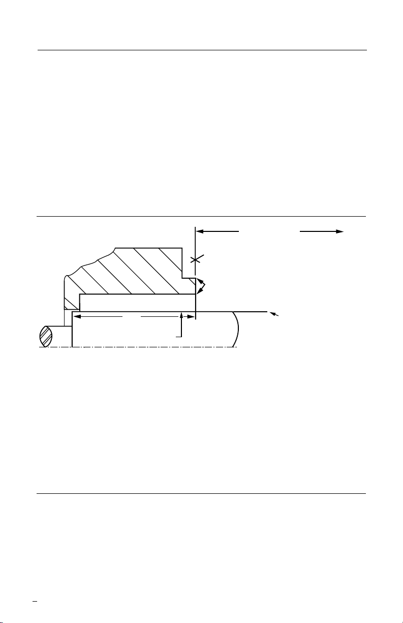
1 Equipment Check
To first obstruction
SS
For hook sleeve designs
Face of seal housing to be square to the axis
of the shaft to within 0.013 mm per millimeter
(0.0005 inches) of seal chamber bore FIM and
have a √1.6 μm (63 μinch) R finish or better
Gland pilot can be at either of these
register locations, concentric to within
0.13 mm (0.005 inch) FIM of shaft or sleeve OD
Sleeve or shaft finish to be
0.8 μm (32 μinch) R or better
Shaft or sleeve OD
+0.000 mm (+0.000 inch)
-0.050 mm (-0.002 inch) ANSI
+0.000 mm (+0.000 inch) API 610/682
-0.025 mm (-0.001 inch) DIN/ISO
• Bearings must be in good condition
• Maximum lateral or axial movement of shaft (end play) = 0.25 mm (0.010 inch) FIM
• Maximum shaft runout at face of seal housing = 0.05 mm (0.002 inch) FIM
• Maximum dynamic shaft deflection at seal housing = 0.05 mm (0.002 inch) FIM
Seal housing bore to have √3.2 μm
(125
μ
inch) R finish or better
a
a
a
1.1 Follow plant safety regulations:
• lock out motor and valves.
• wear designated personal safety equipment.
• relieve any pressure in system.
• consult plant MSDS les for hazardous material regulations.
1.2 Adjust the bearings, coupling, and impeller so that the shaft is in its operating
axial position. Disassemble equipment to allow access to seal installation area.
1.3 Remove all burrs and sharp edges from the shaft, sleeve, seal housing bore and
face, keyways, and any other feature that may contact sealing gaskets.
Replace worn components. Clean all piping plans.
1.4 Check requirements for shaft, sleeve, and seal housing. See Figure 1.
Seal Chamber Requirements Figure 1
1.5 Check assembly drawing included with the seal for equipment dimensions, seal
design, materials of construction, and piping connections.
1.6 Measure all diameters and distances to ensure they are dimensionally the same
as shown on the seal assembly drawing.
1.7 Handle all seal parts with care, they are manufactured to precise tolerances. The
seal faces are of special importance and should be kept perfectly clean.
2 Mechanical Seal Installation
2.1 Review seal assembly drawing, seal assembly, and equipment prior to installation.
Read all notes on the seal assembly drawing. For hook sleeve designs, conrm the
seal setting length shown on the assembly drawing matches the equipment.
See Figure 1.
2.3 Lightly lubricate external gaskets with a lubricant compatible with both handled
2.4 Install the seal onto the shaft and locate it against the face of the seal chamber.
2
product and gasket material. Generally, silicon grease is suitable.
If applicable, ensure the sleeve is aligned with drive features on the shaft.
Page 3

2.5 Orient the ports on the seal gland(s) as indicated by the seal assembly drawing
seal
end view
and connected piping.
2.6 Evenly torque gland bolts/nuts for uniform gland pressure against the seal
chamber. On cartridge seals, do not yet tighten drive collar screws.
2.7 Complete the remaining equipment assembly including bearings, if applicable.
2.8 On cartridge seals, evenly tighten drive collar screws.
2.9 Disengage setting plates from the sleeve and secure in disengaged position.
2.10 Inspect equipment and driver alignment in accordance with coupling and/or
equipment manufacturer’s instructions.
2.11 After bringing the equipment up to operating conditions, recheck alignment and
make adjustments as necessary.
Installed Cartridge Seal Assembly and Plan 23 Figure 2
high point vent,
normally closed
cooling
out
cooling
outlet
inlet
in
temperature
low point drain,
normally closed
3 Piping Instructions
3.1 Refer to the seal assembly drawing for recommended seal piping plans. D seals
are designed for Plan 23, follow all installation and operating instructions provided
with these systems.
3.2 Minimize restrictions, total tubing length and number of bends especially in closed
loop systems. Unless otherwise specied, the minimum internal diameter for tubing
and connecting hardware should be 19 mm (0.750 inch).
3.3 In Plan 23 loop systems, pipe runs should be sloped continuously for proper
venting and draining, and to promote thermosyphoning in standby condition. Include
a high point vent. Unless otherwise specied, coolers must be mounted 45 – 60 cm
(18 – 24 inches) above and up to 90 cm (36 inches) laterally from the center of the
shaft. Reservoirs follow the same vertical guidelines and are allowed up to 120 cm
(48 inches) lateral distance from the center of the shaft.
3.4 Do not start the equipment dry. Vent the equipment, seal chamber, and all
piping systems then startup support systems before starting equipment.
cooler
indicator
3
Page 4

TO REORDER REFER TO
flowserve.com
USA and Canada
Kalamazoo, Michigan USA
Telephone: 1 269 381 2650
Telefax: 1 269 382 8726
Europe, Middle East, Africa
Roosendaal, the Netherlands
Telephone: 31 165 581400
Telefax: 31 165 554590
Asia Pacific
Singapore
Telephone: 65 6544 6800
Telefax: 65 6214 0541
Latin America
Mexico City
Telephone: 52 55 5567 7170
Telefax: 52 55 5567 4224
B/M #
F.O
.
4 Repair
This product is a precision sealing device. The design and dimension tolerances are critical
to seal performance. Only parts supplied by Flowserve should be used to repair a seal. To
order replacement parts, refer to the part code and B/M number. A spare backup seal
should be stocked to reduce repair time.
When seals are returned to Flowserve for repair, decontaminate the seal assembly and
include an order marked "Repair or Replace." A signed certicate of decontamination
must be attached. A Material Safety Data Sheet (MSDS) must be enclosed for any
product that came in contact with the seal. The seal assembly will be inspected and, if
repairable, it will be rebuilt, tested, and returned.
FIS173eng 01/07 Printed in USA
To find your local Flowserve representative
and find out more about Flowserve Corporation,
visit www.flowserve.com
Flowserve Corporation has established industry leadership in the design and manufacture of its products. When
properly selected, this Flowserve product is designed to perform its intended function safely during its useful life.
However, the purchaser or user of Flowserve products should be aware that Flowserve products might be used
in numerous applications under a wide variety of industrial service conditions. Although Flowserve can provide
general guidelines, it cannot provide specific data and warnings for all possible applications. The purchaser/user
must therefore assume the ultimate responsibility for the proper sizing and selection, installation, operation, and
maintenance of Flowserve products. The purchaser/user should read and understand the Installation Instructions
included with the product, and train its employees and contractors in the safe use of Flowserve products in connection
with the specific application.
While the information and specifications contained in this literature are believed to be accurate, they are supplied for
informative purposes only and should not be considered certified or as a guarantee of satisfactory results by reliance
thereon. Nothing contained herein is to be construed as a warranty or guarantee, express or implied, regarding any
matter with respect to this product. Because Flowserve is continually improving and upgrading its product design,
the specifications, dimensions and information contained herein are subject to change without notice. Should any
question arise concerning these provisions, the purchaser/user should contact Flowserve Corporation at any one of
its worldwide operations or offices.
© Flowserve Corporation (2011)
 Loading...