

Page 1

Worcester Actuation Systems
WCAIM2026
DataFlo Digital Electronic Controller DFC17
Installation, Operation and Maintenance Instructions
MODELS:
10 - For
DataFlo
Boards Mounted Inside 10-23 75 Actuators.
25 - For
DataFlo
Boards Mounted Inside 25/30 75 Actuators.
Setpoint Inputs:
DFC17-1K (120A, 240A, or 24D) 1000 ohm Resistance
Setpoint Input
DFC17-13 (120A, 240A, or 24D) 135 ohm Resistance
Setpoint Input
DFC17-1 (120A, 240A, or 24D) 1 to 5 mA Setpoint Input
DFC17-4 (120A, 240A, or 24D) 4 to 20 mA Setpoint Input
DFC17-10 (120A, 240A, or 24D) 10 to 50 mA Setpoint Input
DFC17-5V (120A, 240A, or 24D) 0 to 5 VDC Setpoint Input
DFC17-XV (120A, 240A, or 24D) 0 to 10 VDC Setpoint Input
Voltages:
120A - 120 VAC Power Circuits
240A - 240 VAC Power Circuits
24D - 24 VDC Power Circuits
Page 2

2
DataFlo
Digital Electronic Controller DFC17 Installation, Operation and Maintenance Instructions WCAIM2026
TABLE OF CONTENTS
Page
1.0 GENERAL 4
1.1 Basic Design 4
1.2 Environmental Considerations 4
1.2.1 Temperature 5
1.2.2 Humidity 5
1.2.3 Input Circuit Noise Protection 5
2.0
DataFlo
ELECTRONIC POSITIONER CIRCUIT BOARD 5
2.1 General 5
2.2 Circuit Board Configurations 8
2.3 LED Indicators 8
2.4 Controls (Override) 8
2.5 AC Power Control 8
3.0 WIRING OF DIGITAL CONTROLLER AND SERIES 75 ELECTRIC ACTUATOR 8
3.1 Actuator Power 8
3.1.1 Wire Size 8
3.1.2 Termination and Voltage 8
3.1.3 Minimum Fuse Ratings 8
3.2 Input Signal Connections 9
3.2.1 Milliamp 9
3.2.2 Resistive 9
3.2.3 DC Voltage 9
3.3 4–20 mA (4–75) Position Indicator Option Connections 9
4.0 OPERATION OF THE DIGITAL CONTROLLER 12
4.1 Run Mode 12
4.1.1 Run Mode Menu 12
4.1.2 Mode Change Key Sequence 12
4.1.3 Alarm Displays 12
4.2 Calibration Mode 12
4.2.1 Calibration Mode Menu 12
4.2.2 Key Sequences for Calibrating Setpoint Lower Limit 12
4.2.3 Key Sequences for Calibrating Setpoint Upper Limit 12
4.2.4 Key Sequences for Calibrating Clockwise Position 12
4.2.5 Key Sequences for Calibrating Counter-clockwise Position 14
4.2.6 Key Sequences for Calibrating Analog Process #1 Lower Input Signal 14
4.2.7 Key Sequences for Calibrating Analog Process #1 Upper Input Signal 14
4.2.8 Key Sequences for Calibrating Single-Channel RTD Process Module 14
4.2.9 Key Sequences for Calibrating Optional Two-Channel RTD Process Module 15
4.2.10 Key Sequences for Calibrating Thermocouple Process Module 16
4.2.11 Key Sequences for Calibrating Cycle Time 17
4.3 Program Mode 17
4.3.1 Program Mode Menu 18
4.3.2 Instructions for Editing Parameters 18
4.3.3 Default Values for Process Control (factory installed) 18
4.4 Manual Setpoint Mode 18
4.5 Manual Position Mode 18
4.6 Positioner Mode 18
Flow Control Division
Worcester Actuation Systems
Page 3

WCAIM2026
DataFlo
Digital Electronic Controller DFC17 Installation, Operation and Maintenance Instructions 3
4.7 Auto-Tuning Safety Considerations 21
4.7.1 Things to Know Before Tuning 21
4.7.2 Safety Concerns During Operation 21
4.8 Controller Setup 21
4.8.1 General Setup 21
4.8.2 Tuning the Controller Automatically (Open-Loop Tuning) 21
4.8.3 Tuning the Controller Manually 22
4.8.4 Some Guidelines for Control Parameters 22
5.0 TECHNICAL DATA 23
5.1 Allowable Supply Voltage Range 23
5.2 Analog Input Circuit Specifications 23
5.3 Output Circuit Specifications 23
5.4 Input Circuit Load Resistances 23
6.0 TROUBLESHOOTING 24
6.1 General 24
6.1.1 Cam Adjustment 24
6.1.2 Check Fuse F1 24
6.1.3 Check Basic Actuator for Proper Operation 24
6.1.4 Check for Noise Problems 24
6.1.5 Replace Circuit Board 24
6.2 Symptom Table 25
6.3 Troubleshooting Guidelines 26
Flow Control Division
Worcester Actuation Systems
Page 4
4
DataFlo
Digital Electronic Controller DFC17 Installation, Operation and Maintenance Instructions WCAIM2026
1.0 GENERAL
1.1 Basic Design
The Worcester/McCANNA
DataFlo
Digital Electronic Controller
(DFC17) was designed for use with the Worcester/McCANNA
Series 75 electric actuators. However, it may also be used with
other actuators or electrically operated rotary devices, provided
the specified load parameters as given in Section 5.3 are not
exceeded.
CAUTION: This controller is sensitive to electrical noise;
please see Section 1.2
PLEASE READ THIS SECTION
A. The 4–20 mA Setpoint signal input circuit of both the AC
and DC Digital Controller board is protected with a 62 mA
fuse (F1). The fuse is used to protect the input circuit
from an excessively high voltage. The fuse used in the
input circuit is a Littlefuse PICO II very fast-acting fuse
rated at 62 mA.
All DC Digital Controller boards also use a standard 1
1
/
4",
250 volt, 3 amp fuse (F2) to protect the circuit board and
the power source in case of a fault in the DC motor driver
integrated circuit on the circuit board.
CAUTION: It is important that the DC voltage power
source be connected properly to the actuator’s terminal
strip. Terminal one (1) of this strip is to have the
negative or common wire connected to it. Terminal two
(2) is to have the positive wire connected to it.
Note: All wiring to terminal strip should be inserted only
to mid-point of terminal strip.
For 240 VAC Digital Controller only, limit switches do not
directly control the motor(s). Therefore, the actuator will
not stop when the limit switches trip. Use care not to
drive the actuator past its normal limits.
B. The Digital Controller board requires both a setpoint input
signal and a process input signal.
C. The Digital Controller board can be set up in several ways
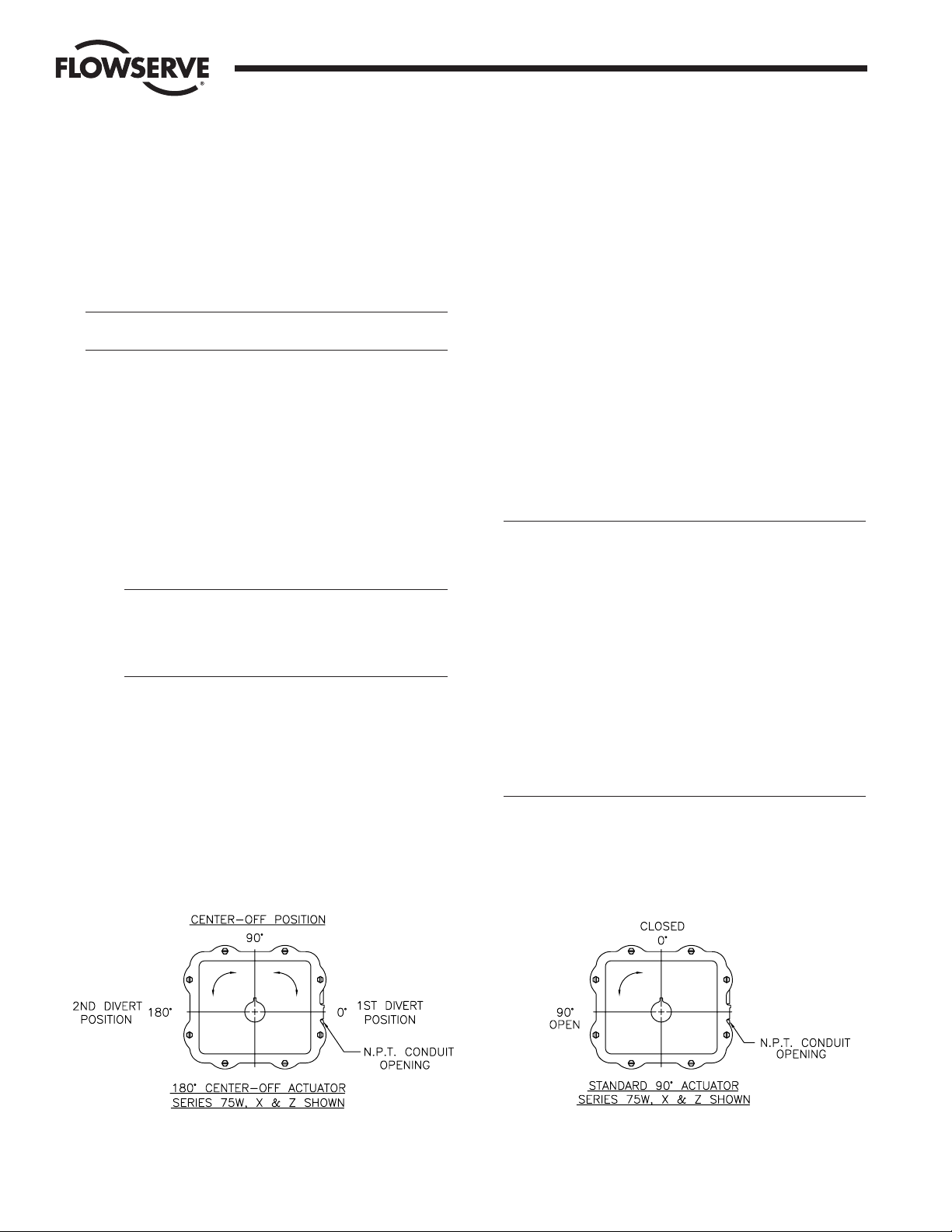
for normal operation. The board is designed to control in
90° quadrants only (with alternate potentiometer gearing,
180° of rotation is available). The number of quadrants
over which the board will control is determined by the
number of teeth on the feedback pot pinion gear.
D. Quite often when we receive an actuator for repair, we
find that the only thing wrong with the unit is that the
feedback potentiometer is out of calibration. It is very
important that the feedback pot be properly calibrated for
correct operation of the Controller board. It is also very
important that the actuator shaft not be rotated out of the
quadrant for which the feedback potentiometer has been
calibrated. Whenever you have a problem with the
Controller calibration, always check the feedback
potentiometer calibration first. See paragraph 6.3.6 in the
troubleshooting section.
1.2 Environmental Considerations
CAUTION: The
DataFlo
Digital Electronic Controller is sensitive
to electrical noise on signal, process, or supply lines and in
the environment. For maximum controller sensitivity, the
electrical noise level should be as low as possible. Follow
installation and calibration guidelines carefully and use
shielded wire as stated in paragraph 1.2.3.
Flowserve recommends that all products which must be stored
prior to installation, be stored indoors, in an environment
suitable for human occupancy. Do not store product in areas
where exposure to relative humidity above 85%, acid or alkali
fumes, radiation above normal background, ultraviolet light,
or temperatures above 120°F or below 40°F may occur. Do not
store within 50 feet of any source of ozone.
Temperature and humidity are the two most important factors
that determine the usefulness and life of electronic equipment.
Flow Control Division
Worcester Actuation Systems
Quadrants of Operation
Page 5

WCAIM2026 DataFlo Digital Electronic Controller DFC17 Installation, Operation and Maintenance Instructions 5
1.2.1 Temperature
Operating solid state electronic equipment near or beyond
its high temperature ratings is the primary cause for most
failures. It is, therefore, very important that the user be
aware of and take into consideration, factors that affect the
temperature at which the electronic circuits will operate.
Operating an electronic device at or below its low
temperature rating generally results in a unit operating
poorly or not at all, but it will usually resume normal
operation as soon as rated operating temperatures are
reached. Low temperature problems can be easily cured
by addition of a thermostatically controlled heater to the
unit’s housing.
The Worcester/McCANNA
DataFlo
Digital Electronic
Controller is rated for operation between -40°F (with
heater and thermostat) and 160°F. When using the
Controller inside the Worcester/McCANNA 75 Series
actuators, a maximum ambient temperature of 115°F is
required to ensure the circuit board maximum
temperature of 160°F is not exceeded.
Temperature Ranging allows the user to specify the actual
process temperature conditions within the stipulated range
of the measuring element, i.e., RTD or thermocouple. The
control range can be as little as 50°C or 100°C
respectively, or to the full range of the measuring device.
For temperatures above 600°C, consult factory.
1.2.2 Humidity
Most electronic equipment has a reasonable degree of
inherent humidity protection and additional protection is
supplied by the manufacturer, in the form of moisture
proofing and fungicidal coatings.
Such protection, and the 3 to 4 watts of heat generated
by the circuit board assembly, will generally suffice for
environments where the average relative humidity is in
the area of 80% or less and ambient temperatures are in
the order of 70°F average. Where relative humidity is
consistently 80 to 90% and the ambient temperature is
subject to large variations, consideration should be given
to installing a heater and thermostat option in the
enclosure. The heater should not increase the enclosure
temperature to the point where the circuit board assembly
temperature rating of 160°F is exceeded.
In those instances where the internal heater would bring
the circuit board’s operating temperature near or above its
maximum rating, the user might consider purging the
enclosure with a cool, dry gas. The initial costs can
usually be paid off quickly in the form of greatly extended
equipment life, low maintenance needs, and much less
process downtime.
1.2.3 Input Circuit Noise Protection
Shielded wiring should be used for all setpoint and
process signal input circuit wiring regardless of length.
With separately housed Controllers, the wiring from the
feedback potentiometer to the remote Controller, would
be considered as signal input wiring
and should also be
shielded wire
.
The shields should never be used in place of one of the
input wires, and the shields should be grounded to
equipment housings at one end of the wiring run only.
Grounding both ends of shielding can eliminate the
shielding benefits because of current ground loops. If two
or more shielded cables come to the Controller from
different locations, ground the shields at the Controller.
2.0
DataFlo
ELECTRONIC
CONTROLLER CIRCUIT BOARD
2.1 General
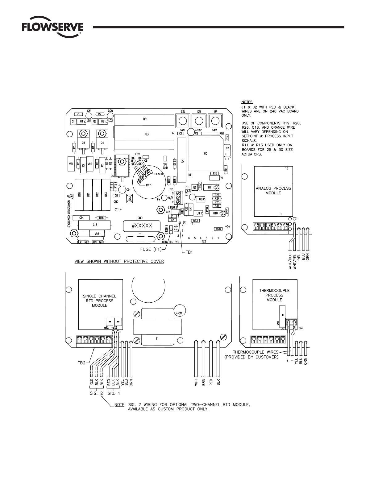
Figure 1 defines the location of major components and wires
from the Controller Board to terminal strip connections. The
Digital Controller Board is factory wired to the terminal strip
either per Figure 2, Figure 3, or Figure 4, as found in Section 3.0,
depending on power circuit voltage.
The feedback potentimeter leads are factory connected to the
terminal block (TB1) on the Digital Controller Board.
2.2 Circuit Board Configurations
The Controller circuit board is factory supplied in one of several
possible configurations:
A. The Controller circuit board will accept one of the
following setpoint signal inputs, depending on the circuit
board ordered:
• 4–20 mA
• 1–5 mA
• 10–50 mA
• 0–5 VDC
• 0–10 VDC
• 135 ohm pot
• 1000 ohm pot
In addition, the setpoint value can be set remotely via the
RS 485 interface, or locally with the circuit board
switches. When the setpoint is entered locally, all other
means of entering the setpoint are temporarily disabled.
Flow Control Division
Worcester Actuation Systems
Page 6
6
DataFlo
Digital Electronic Controller DFC17 Installation, Operation and Maintenance Instructions WCAIM2026
Flow Control Division
Worcester Actuation Systems
Figure 1 – Digital Electronic Controller Circuit Board, 120/240 VAC
Page 7

WCAIM2026
DataFlo
Digital Electronic Controller DFC17 Installation, Operation and Maintenance Instructions 7
Flow Control Division
Worcester Actuation Systems
Figure 1 – Digital Electronic Controller Circuit Board, 24 VDC
Page 8

8
DataFlo
Digital Electronic Controller DFC17 Installation, Operation and Maintenance Instructions WCAIM2026
B. The Controller circuit board will accept one of the
following process signal inputs, depending on the circuit
board ordered:
One of the following analog inputs:
4–20 mA
1–5 mA
10–50 mA
0–5 VDC
0–10 VDC
135 ohm pot
1000 ohm pot
One 100 ohm Platinum RTDs – NOTE: A single channel is
standard. A two channel is available as a custom product
and must be hard wired to the red and two black leads
from circuit board identified as signal 2.
A single J, K, T, or E type Thermocouple
NOTE: Field changes to the Controller board are not
advised. Consult Flowserve before attempting any
modification.
2.3 LED Indicators
Light emitting diodes (LED) marked LD1 (CW) and LD2 (CCW)
are in the output circuits and when lit indicate which direction
the actuator is trying to drive. A third LED, LD3, is used to
indicate when an alarm condition exists. If LD3 is lit, the alarm
that caused it to light must be determined by looking at the
liquid crystal display (LCD) and finding the alarm parameter with
the UP or DN switch.
2.4 Controls (Override)
There are no adjustable controls provided on the circuit board
because none are necessary. All parameters are set through the
programming switches (keys) or the RS485 interface. Local
pushbutton control is provided at the actuator by simultaneously
pressing the SEL and UP switches (keys) for three seconds. At
this point the UP and the DN switches (keys) can be used to
manually position the actuator shaft. Pressing the SEL switch for
three seconds will return the Controller to the run mode.
2.5 AC Power Control
The AC output circuits are controlled by solid state switches
(triacs Q3, Q4), which will provide trouble-free operation for the
life of the equipment they are used with,
AS LONG AS THEY ARE
OPERATED WITHIN THEIR RATINGS
.
The ratings for the solid state switches used in the Worcester
DataFlo
Digital Electronic Controller are listed in part 5.3.
3.0 WIRING OF DIGITAL CONTROLLER
AND SERIES 75 ELECTRIC
ACTUATOR
See wiring diagrams located under actuator cover and/or Figures 2
through 4 for customer connections.
3.1 Actuator Power
CAUTION: Wiring should be inserted only to mid-point of
terminal strip.
3.1.1 Wire Size
Power to the Controller and from the Controller to the
actuator should be with wire no smaller than #18 gauge
and with insulation rated for the particular application.
The #18 gauge wire size is sufficient for all Worcester
Series 75 actuators. When using the Controller with other
makes of actuators, check the manufacturer’s current
rating to determine the correct wire size.
3.1.2 Termination and Voltage
Power connections are made to terminals 1 and 2 of the
terminal strip. The AC neutral or common, or DC
negative wire should be connected to terminal #1 and
the AC “Hot” or DC positive wire to terminal #2. Note
that the AC Controller requires a minimum of 110 VAC,
and a maximum of 130 VAC for the 120 VAC version and
a 220 VAC minimum, 250 VAC maximum for the
240 VAC version.
Grounding wires should be connected to green colored
grounding screw (if present) on actuator base or to any
base plate mounting screw in the actuator.
3.1.3 Minimum Fuse Ratings
See Minimum Fuse Rating table when overcurrent
protection is used in motor power circuit.
Minimum Fuse Rating for Overcurrent Protection
Actuator Size Voltage Fuse Rating
10-23 120 VAC 5 A
25/30 120 VAC 10 A
10-23 240 VAC 3 A
25/30 240 VAC 5 A
10-23 24 VDC 5 A
NOTE: This table shows the minimum rating to prevent inrush current
from blowing the fuse.
Flow Control Division
Worcester Actuation Systems
Page 9

WCAIM2026
DataFlo
Digital Electronic Controller DFC17 Installation, Operation and Maintenance Instructions 9
3.2 Input Signal Connections
NOTES: The Digital Controller setpoint input signal circuit is
protected by
1
/
16 amp fuse, F1 (See Figure 1 and Paragraph A of
Part 1.1).
A label on the circuit board indicates the controllers setpoint and
process signal configurations. See Section 5.2 for input signal
specifications.
After input signal connections have been made, securely tighten
all terminal screws. Keep wiring away from all rotating parts and
ensure it will not be pinched when the actuator cover is installed.
3.2.1 Milliamp
DFC17-1, DFC17-4, DFC17-10 (Milliamp Setpoint Input
Signal for Digital Controller)
For a milliamp setpoint signal input, the more positive or
“High” signal lead should connect to actuator terminal 11.
The less positive or “Common” lead should connect to
actuator terminal 10. [Terminal 10 is (), Terminal 11
is (+).]
The Controller is available for use with the following
signals: 1 to 5, 4 to 20, and 10 to 50 milliamps. The
Controller board is factory calibrated for one of the three
milliamp signal ranges and field changes are not advised.
Part 5.4 gives the nominal resistance load, which the
Controller presents to the control circuit for the three
signal ranges.
Comparison of resistance measurements made at
terminals 10 and 11 (on the yellow and blue wires from
the circuit board) against the resistances shown in Part
5.4 provides a quick way to determine the milliamp range
for which a particular board is calibrated. If fuse F1 is
blown, an open circuit will be indicated.
NOTE: If the circuit board has an orange wire (See
Figure 1) attached to it, the board is set up for a
Potentiometer Setpoint Input. See paragraph 3.2.2.
3.2.2 Resistive
DFC17-13, DFC17-1K (Potentiometer Setpoint Input for
Digital Controller)
NOTE: The Setpoint Input Potentiometer is not the
Feedback Potentiometer, but is an additional
Potentiometer provided with the Controller, and externally
located by the end user. The acceptable potentiometer
values are 135 ohm for the DFC17-13 board and 1000
ohms for the DFC17-1K board.
For a potentiometer setpoint input signal, the usual
connections will be as shown in Figures 2 through 5 with
a “Low” setpoint command being generated when the
potentiometer is rotated to its full CCW position and a
“High” setpoint command when it is in the full CW
position.
If the setpoint command signal is derived from other than
a rotary potentiometer, it is only necessary to keep in
mind that a “Low” (full CCW) setpoint signal is called for
when the command potentiometer presents the least
resistance between terminals 10 and 11 and the most
resistance between terminals 11 and 12. A “High” (full
CW) setpoint signal would be the reverse condition; the
least resistance between terminals 11 and 12 and the
most resistance between terminals 10 and 11.
If the “Setpoint Command” potentiometer is reasonably
linear, the setpoint will be approximately 50% when the
potentiometer shaft is halfway through its travel.
3.2.3 DC Voltage
DFC17-5V, DFC17-XV (Direct Voltage Setpoint Input
Signal for Digital Controller)
For a voltage setpoint input signal, the more positive or
“High” signal lead should connect to terminal 11. The less
positive or “Common” lead should connect to terminal
10. (Terminal 10 is (), Terminal 11 is (+).)
The Controller is available for use with the following direct
voltage setpoint input signals: 0 to 5 VDC and 0 to 10
VDC. The Controller board is factory calibrated for one of
these two signal ranges and field changes are not advised.
Part 5.4 gives the nominal resistance load which the
Controller presents to the control circuit for the two
signal ranges.
3.3 4–20 mA (4-75) Position Indicator Option Connections
For units with a 4–20 mA (4–75) position indicator option
installed (indicator board installed over limit switches) the red
and black wires from the position indicator board will have to be
spliced directly to the external positive and negative output
(meter) wires respectively.
Note: Before wiring, calibrate indicator board per the following
paragraph. All other wiring of option, including the dual
potentiometer, has been done at the factory.
To obtain proper 4–20 mA output, the indicator board output has
to be calibrated prior to wiring red and black wires. Using an
ammeter connected to the red and black wires of the indicator
board, adjust the two potentiometers R4 and R5 on the board.
With the actuator in the closed position (0%), adjust R5
potentiometer (adjacent to the number “4” etched on the circuit
board and closest to terminal block) to obtain 4 mA on the
ammeter. Move the actuator to the open position (100%) and
adjust R4 potentiometer (adjacent to the number “20” etched on
the circuit board) to obtain 20 mA. Because adjustment of one
potentiometer affects the other, repeat the procedure several
times to obtain proper values.
NOTE: If a dual pot option only is installed, the “B” pot leads will
have to be wired directly to external device. The “A” pot leads
are factory connected to the terminal Block (TB1) on the Digital
Controller Board. Also, note that the “B” potentiometer has a
voltage limit of 30 volts maximum.
Flow Control Division
Worcester Actuation Systems
Page 10

10
DataFlo
Digital Electronic Controller DFC17 Installation, Operation and Maintenance Instructions WCAIM2026
Flow Control Division
Worcester Actuation Systems
Figure 2 Figure 3
NOTE: For all input signal circuit wiring, regardless of length, shielded wiring should be used. See Section 1.2
Page 11

WCAIM2026
DataFlo
Digital Electronic Controller DFC17 Installation, Operation and Maintenance Instructions 11
Flow Control Division
Worcester Actuation Systems
Figure 4 – 24 VDC DFC17 Circuit Board Wiring
Figure 5
Model 485F9 (9 pin)
or 485F (25 pin)
485 Converter
1.5K
1.5K
PWR SUPPLY +9 VDC
PWR SUPPLY GND
TB2
TB2
2
1
9
8
Receive -
Receive +
Wht/Blk
Purple
Internal External
Actuator Terminal
Strip
(SHIELD)
(NO CONNECTION)
EN\
TX
TX\
RX\
RX
Sample RS-485 Connection
Controller Board
NOTE: If you are not using the RS-485 converter as shown in Figure 5, then refer to the documentation that came with your converter for proper
connections.
ICS
GND
GND
VDC
Page 12

12
DataFlo
Digital Electronic Controller DFC17 Installation, Operation and Maintenance Instructions WCAIM2026
4.0 OPERATION OF THE DIGITAL
CONTROLLER
Refer to RS485 Communications software diskette included with
controller for more information.
The DFC17 Controller is capable of being operated in several modes.
The normal mode of operation is the RUN mode. Following is a list of
the various modes and the key sequences necessary to enter each of
them and the function of each of the parameters within that mode:
4.1 Run Mode “run”
This is the normal operating mode.
While in the Run Mode momentarily pressing:
SEL Toggles between alternating name/value and continuous
value display.
UP Shows the next parameter.
DN Shows the previous parameter.
4.1.1 Run Mode Menu
Pressing SEL while the alarm condition is alternating on
the display will freeze the display with the highest priority
alarm showing. At that point, pressing SEL again will
attempt to reset the alarm display. If the alarm
condition(s) still exist after pressing SEL, the display will
continue to show the alarm(s).
See table on page 13.
4.1.2 Mode Change Key Sequence
See table on page 13.
4.1.3 Alarm Displays
See table on page 13.
4.2 Calibration Mode
Press SEL + DN keys for three seconds to enter Calibration Mode
CAL from Run Mode. A security code may be required for entry
to the Calibration Mode. If one is required, it is checked and
entered using the instructions below and for editing a numeric
value as described in paragraph 4.3.2.
Simultaneously press and hold the SEL and DN keys for three
seconds. CAL will be displayed for two seconds and the security
code will be checked. If the required security code is not zero
(“0000”), the display will begin alternating between “CodE” and
“0000”. If the required security code is zero, it will not need to be
entered, i.e., it will be bypassed and display will automatically
flash “SEtL”. Skip to paragraph 4.2.2.
Enter the security code, if necessary, as follows. (If the code is
forgotten, the special number 4800 can be used to gain entry).
Quick tap SEL key once. First 0 will flash. Quick tap UP key until
you reach code number. Quick tap the DN key once. The second
0 will flash Quick tap the UP key until the next code number is
reached. Continue this procedure as needed for the remaining
code numbers. Quick tap SEL to accept code.
Display now flashes between “SEtL” and a value.
Press SEL key for two seconds to return to the Run Mode.
For the Calibration Mode Menu table, press:
SEL To sequence through the calibration parameters.
SEL + UP To enable/start calibration of the selected parameter.
4.2.1 Calibration Mode Menu
See table on Page 14.
4.2.2 Key Sequences for Calibrating Setpoint Lower Limit
The lower setpoint parameter SEtL should be displayed.
Press SEL + UP to begin calibrating the parameter.
Attach an accurate current source to the setpoint signal
input and adjust the source to produce a 4 mA signal. The
voltage reading on the display should be less than 1 volt.
Press SEL
to accept the value shown and return to the
calibration menu.
4.2.3 Key Sequences for Calibrating Setpoint Upper Limit
Press DN to select the upper setpoint parameter SEtU
Press SEL + UP to begin calibrating the parameter.
Attach an accurate current source to the setpoint signal
input and adjust the source to produce a 20 mA signal.
The voltage reading on the display should be between
3.800 and 5.000 volts.
Press SEL to accept the value shown and return to the
calibration menu.
4.2.4 Key Sequences for Calibrating Clockwise Position
Press DN to select the clockwise setpoint parameter PoC
Press SEL + UP to begin calibrating the parameter.
1) Use either the UP or DN switches to manually rotate
the actuator to its full clockwise (CW) position.
2) With the actuator in the full CW position, adjust the
feedback potentiometer by rotating the face gear
located on the actuator shaft with your fingers, for a
reading between .200 and .400 volts.
NOTE: It is not necessary to loosen or remove face gear
snap ring(s) (if present) to rotate gear, it is a friction fit.
For gears that do have snap rings, and if for any reason
the snap ring(s) must be removed, do not overstretch
them. Use the minimum opening to allow the rings to slip
over the gear.
Press SEL to accept the value shown and return to the
calibration menu.
Flow Control Division
Worcester Actuation Systems
Page 13

WCAIM2026
DataFlo
Digital Electronic Controller DFC17 Installation, Operation and Maintenance Instructions 13
Flow Control Division
Worcester Actuation Systems
Table 4.1.1 Run Mode Menu
Display Description Units
Pr1 Process #1 signal value. Engineering
Pr2 Process #2 signal value. Engineering
Pr12 Average of process #1 and process #2 signal values. Engineering
SEt - Setpoint value. Only one of the following will be displayed: Engineering
SEtA – analog setpoint; SEtP – digital setpoint;
SEtL – local manual setpoint.
PtEr Proportional term value.
itEr Integral term value.
dtEr Derivative term value.
ALr Alarm. Alarm shown is highest priority. See Mode Change
Key Sequence table.
POS Valve position. Percent
CYCn Number of cycles. Times 1000
cycles
PHi Highest recorded process value. Engineering
PLo Lowest recorded process value. Engineering
Table 4.1.2 Mode Change Key Sequence
Press Key(s) for Three Seconds Mode Entered
SEL Program Mode.
SEL + DN Calibration Mode.
SEL + UP Manual Setpoint Mode.
SEL + DN + UP Manual Position Mode (gives access to Auto Tuning).
Table 4.1.3 Alarm Displays
Display Description
PrHi Process high limit alarm.
PrLo Process low limit alarm.
Hi Shaft upper position alarm.
Lo Shaft lower position alarm.
SHFt Invalid shaft position alarm.
Pro Invalid process value alarm.
SEt Invalid setpoint value alarm.
thEr Motor driver circuit thermal warning alarm (DC motors only).
Page 14

14
DataFlo
Digital Electronic Controller DFC17 Installation, Operation and Maintenance Instructions WCAIM2026
4.2.5 Key Sequences for Calibrating Counter-clockwise Position
Press DN to select the counter-clockwise setpoint
parameter PoCC
Press SEL + UP to begin calibrating the parameter.
1) Use either the UP or DN switches to manually rotate
the actuator to its full counter-clockwise (CCW)
position.
2) With the actuator in the full CCW position, the voltage
reading on the display should be greater than 3.000
volts. If not, recheck PoC. If it is correct and the PoCC
reading is still not correct, contact factory.
Press SEL to accept the value shown and return to
the calibration menu.
4.2.6 Key Sequences for Calibrating Analog Process #1 Lower
Input Signal
This procedure is followed only if an analog process
module is used.
Press DN to select the lower input parameter PrlL
Press SEL + UP to begin calibrating the parameter.
Attach an accurate current source to the process input
and set a current of 4.0 mA. The voltage reading on the
display should be less than 1 volt.
Press SEL to accept the value shown and return to the
calibration menu.
4.2.7 Key Sequences for Calibrating Analog Process #1 Upper
Input Signal
This procedure is followed only if an analog process
module is used.
Press DN to select the upper input parameter PrlU
Press SEL + UP to begin calibrating the parameter.
Attach an accurate current source to the process input
and set a current of 20 mA. The voltage reading on the
display should be greater than 3.000 volts
Press SEL to accept the value shown and return to the
calibration menu.
4.2.8 Key Sequences for Calibrating Single Channel RTD Process
Module
This procedure is followed only if a single channel RTD
process module is used. With this type of process
module, an attached 100 ohm platinum RTD develops a
voltage representing the temperature of the process.
RTDs can cover a very wide temperature range. The RTD
module however allows a narrower temperature range to
be used. This is useful for applications that need higher
resolution and do not need a wide range.
The purpose of this procedure is to specify the
temperature units, temperature range, and to record the
actual voltage values at the lower and upper process
limits. This procedure involves adjusting components on
the RTD module. This procedure is entered by selecting
either the Pr1L or Pr1U parameter for calibration. When
either of those parameters is selected for calibration, the
controller starts the following calibration sequence. At any
time in the menu, the user can press the SEL key to
return to the calibration menu.
Any one step in the calibration procedure can be
performed without performing the others. However, it is
recommended to perform all the calibration steps if any
one item is changed.
Calibrating the RTD module circuitry involves adjusting
the span and zero potentiometers on the module to
achieve a good voltage swing for the temperature range
selected. When adjustments have been properly
completed, the calibration routine will use the calibrated
analog voltages to create a linearization table.
Flow Control Division
Worcester Actuation Systems
Table 4.2.1 Calibration Mode Menu
Display Description Acceptable Range
SEtL Setpoint lower limit signal value. Less than 1 volt.
SEtU Setpoint upper limit signal value. Between 3.800 volts
and 5.000 volts.
PoC Shaft position feedback value at full clockwise position. Between .200 volts and .400 volts.
PoCC Shaft position feedback value at full counter-clockwise position. Greater than 3.0 volts.
PrlL Process #1 signal lower limit value. Unique to process.
PrlU Process #1 signal upper limit value. Unique to process.
Pr2L Process #2 signal lower limit value. Unique to process.
Pr2U Process #2 signal upper limit value. Unique to process.
CYt Cycle time measurement. Dependent on actuator.
Page 15

WCAIM2026
DataFlo
Digital Electronic Controller DFC17 Installation, Operation and Maintenance Instructions 15
The table above shows a calibration step and the
procedure required to complete the step. It is
recommended to perform all the calibration steps if any
one item is changed. Any time a potentiometer is adjusted,
both the AdcL and AdcU procedures must be performed.
Press the DN key until the PrlL parameter appears. On
that display, press the SEL and UP keys simultaneously to
enter the RTD calibration menus.
On the menus, use the DN key to move from one
parameter to the next one in sequence. When calibration
is completed, press and hold the SEL key for three
seconds to return to the main Calibration Mode menu (the
PrlL parameter). Release and then press the SEL key
again for three seconds to return to the RunMode.
Note: When the RTD temperature units are changed, the
upper range limit will be changed to the default maximum
range shown below.
Default (maximum)
Temperature Units temperature range
°C -200 to +800
°F -300 to +999
Note: Maximum allowable span is 800°C, e.g., -200°C to
+600°C or 0°C to 800°C. Minimum span is 50°C. Span
must be set in 50°C increments.
The procedure for calibrating the module will involve
adjusting the span and zero potentiometers on the RTD
module. Since there can be some interaction between the
two pots, the lower and upper limits are adjusted in the
step for the upper limit. The lower limit procedure is used
only to record the lower limit voltage and no adjustments
should be made in that step.
When adjusting the potentiometers for the upper and
lower limit, the voltage range should be as great as
possible for the best resolution. However, some
guard band area should be left for the possibility of
temperatures slightly outside the specified range. For
example, if the lower limit voltage was 0.100 volts and the
upper limit voltage was 4.900 volts, that would give very
good resolution, but would not allow much room for
temperatures outside of the specified limits. A span of
0.500 and 4.500 might be better.
Flow Control Division
Worcester Actuation Systems
Step Display Procedure
Press SEL and UP to change the temperature units. When SEL and UP are pressed, the units will begin flashing.
Unit Pressing the UP or DOWN keys will change the units between degrees Fahrenheit and Celsius. When the correct
units are flashing, press SEL to lock in the selection.
Press SEL and UP to change the temperature range upper limit. When SEL and UP are pressed, the upper limit will
begin flashing. Pressing the UP or DOWN keys will change the upper limit to another value. When the correct
rn9U range value is flashing, press SEL to lock in the selection. The upper limit of the range will not be able to be
set to a value that is less than 50°C (100°F) above the lower limit (i.e., there must be at least 50°C or 100°F
between limits).
Press SEL and UP to enter the voltage display mode. Be sure a resistance type RTD simulator is attached in place
of the RTD. Simulate the upper limit temperature and adjust the span potentiometer on the module such that the
voltage is between 4.200 and 4.700 volts on the display. Change the RTD simulator to simulate the lower limit
RdcU temperature and adjust the zero potentiometer on the module such that the voltage is between 0.200 and 0.800
volts. Repeat the above process until the upper and lower voltages are within the stated limits. When completed,
be sure the simulator is simulating the upper limit temperature. Press the SEL key to lock in the upper limit voltage.
Press SEL and UP to change the temperature range lower limit. When SEL and UP are pressed, the lower limit will
rn9L begin flashing. Pressing the UP or DOWN keys will change the lower limit to another value. When the correct range
value is flashing, press SEL to lock in the selection. The lower limit of the range will not be able to be set to a value
that is greater than 50°C (100°F) below the upper limit (i.e., there must be at least 50°C or 100°F between limits).
Press SEL and UP to enter the voltage display mode. Be sure a resistance type RTD simulator is attached in place
Rdcl of the RTD. Enter the lower limit temperature (either 0°C or 32°F) in the simulator. The resulting voltage reading
will be displayed.
Do NOT adjust either the zero or span potentiometers in this step.
Press the SEL key to lock in
the lower limit voltage. Note that zero adjustments are made in the procedure for the upper limit. This step is just
used to record the lower limit voltage.
Page 16

16
DataFlo
Digital Electronic Controller DFC17 Installation, Operation and Maintenance Instructions WCAIM2026
4.2.9 Key Sequences for Calibration of Optional Two-Channel
RTD Process Module
A. Key Sequences for Calibrating Two-Channel RTD
Process #1 Input Signal
This procedure is followed only if a two channel RTD
process module is used. This step calibrates both the
lower and upper process signals for input #1.
Press DN to select the lower input parameter PrlL
Press SEL + UP to begin calibrating the parameter.
1) Attach a calibrated RTD simulator to process
input #1.
2) Select an RTD resistance that corresponds to
-100°C. The voltage corresponding to the
resistance is shown on the display as “X.XX”.
3) Press the UP switch to record the lower
temperature value.
4) Select an RTD resistance that corresponds to
+350°C. The display will show a differential
voltage as “dX.XX”. The d indicates that the
displayed value is the difference between the
actual current voltage and the recorded lower
temperature voltage.
5) Adjust the span potentiometer for a differential
voltage reading of “d4.60” volts.
6) Repeat steps 2) through 5) until the voltage
difference reads “d4.60” without further
adjustments.
Press SEL to accept the value shown and return
to the calibration menu.
B. Key Sequences for Calibrating Two-Channel RTD
Process #2 Input Signal
This procedure is followed only if a two channel RTD
process module is used. This step calibrates both the
lower and upper process signals for input #2. Follow
this step only if an RTD is connected to the process
#2 input.
Press DN to select the lower input parameter Pr2L.
Press SEL + UP to begin calibrating the parameter.
1) Attach a calibrated RTD simulator to process
input #2.
2) Select an RTD resistance that corresponds to
-100°C. The voltage corresponding to the
resistance is shown on the display as “X.XX”.
3) Press the UP switch to record the lower
temperature value.
4) Select an RTD resistance that corresponds to
+350°C. The display will show a differential
voltage as “dX.XX”. The d indicates that the
displayed value is the difference between the
actual current voltage and the recorded lower
temperature voltage.
5) Adjust the span potentiometer for a differential
voltage reading of “d4.60” volts.
6) Repeat steps 2) through 5) until the voltage
difference reads “d4.60” without further
adjustments.
Press SEL to accept the value shown and return
to the calibration menu.
4.2.10 Key Sequence for Calibrating Thermocouple Process
Module
With this type of process module, an attached
thermocouple develops a voltage representing the
temperature of the process. Thermocouples can cover a
very wide temperature range. The thermocouple module
however allows a narrower temperature range to be used.
This is useful for applications that need higher resolution
and do not need a wide range.
The purpose of this procedure is to specify the
thermocouple type, temperature units, temperature range,
and to record the actual voltage values at the lower and
upper process limits. This procedure involves adjusting
components on the thermocouple module. This procedure
is entered by selecting either the Pr1L or Pr1U parameter
for calibration. When either of those parameters is
selected for calibration, the controller starts the following
calibration sequence. At any time in the menu, the user
can press the SEL
key to return to the calibration menu.
Note: For greatest accuracy, the thermocouple simulator
should be connected to the controller input module, and
the simulator and the controller board should be turned
on and allowed to temperature stabilize for at least 15
minutes prior to calibrating. The minimum allowable
temperature span is 100°C (212°F).
Any one step in the calibration procedure can be
performed without performing the others. However, it is
recommended to perform all the calibration steps if any
one item is changed.
Calibrating the thermocouple module circuitry involves
adjusting the gain potentiometer on the module to
achieve the desired temperature range. When
adjustments have been properly completed, the
calibration routine will use the calibrated analog voltages
to create a linearization table.
The table below shows a calibration step and the
procedure required to complete the step. It is
recommended to perform all the calibration steps if any
one item is changed.
Press the DN key until the Pr1L parameter appears. On
that display, press the SEL and UP keys simultaneously to
enter the thermocouple calibration menus.
Flow Control Division
Worcester Actuation Systems
Page 17

WCAIM2026
DataFlo
Digital Electronic Controller DFC17 Installation, Operation and Maintenance Instructions 17
On the menus below, use the DN key to move from one
parameter to the next one in sequence. When calibration
is completed, press and hold the SEL key for three
seconds to return to the main Calibration Mode menu (the
Pr1L parameter). Release and then press the SEL key
again for three seconds to return to the Run Mode.
Note: When either the thermocouple type or units is
changed, the upper range limit will be changed to the
maximum upper limit as described earlier. The lower
range limit is always fixed at 0°C or 32°F.
Thermocouple Types and Temperature Ranges
For a controller with a thermocouple module, different
types of thermocouples can be used to measure process
temperature. Some types have wider available
temperature ranges than others. The maximum range
available for the type used is shown in the table at right.
A narrower range can be specified in the Calibration
Mode. Narrowing the range will increase the resolution of
the process temperature measurement and will allow for
better setpoint control.
Thermocouple Range Range
Type Lower Limit Upper Limit
E 0°C 350°C
32°F 650°F
J 0°C 500°C
32°F 900°F
K 0°C 550°C
32°F 999°F
T 0°C 400°C
32°F 750°F
4.2.11 Key Sequences for Calibrating the Cycle Time
Press DN to select the cycle time parameter Cyt.
Press SEL + UP to perform the cycle time measurement.
Flow Control Division
Worcester Actuation Systems
Step Display Procedure
tyPE Press SEL and UP to change the thermocouple type. When SEL and UP are pressed, the type will begin
flashing. Pressing the UP or DOWN keys will change the display to another type. When the correct value
is flashing, press SEL to lock in the selection.
Unit Press SEL and UP to change the temperature units. When SEL and UP are pressed, the units will begin
flashing. Pressing the UP or DOWN keys will change the units between degrees Fahrenheit and Celsius.
When the correct units are flashing, press SEL to lock in the selection.
rn9U Press SEL and UP to change the temperature range upper limit. When SEL and UP are pressed, the
upper limit will begin flashing. Pressing the UP or DOWN keys will change the upper limit to another
value. When the correct range value is flashing, press SEL to lock in the selection. The upper limit of the
range will not be able to be set below 100°C or 212°F.
RdcU Press SEL and UP to enter the voltage display mode. Be sure a thermocouple simulator is attached in
place of the thermocouple. Simulate the upper limit temperature and adjust the gain potentiometer on the
module such that the voltage is between 4.200 and 4.700 volts on the display. Press the SEL key to lock
in the upper limit voltage.
rn9L The value given with this display is the lower temperature limit and is shown to remind the technician of
the temperature to use for the simulator. This value is fixed and not programmable.
RdcL Press SEL and UP to enter the voltage display mode. Be sure a thermocouple simulator is attached in
place of the thermocouple. Enter the lower limit temperature (either 0°C or 32°F) in the simulator.
The
resulting voltage reading will be displayed. Do NOT adjust the gain potentiometer in this step.
Press the
SEL key to lock in the lower limit voltage.
Page 18

18
DataFlo
Digital Electronic Controller DFC17 Installation, Operation and Maintenance Instructions WCAIM2026
4.3 Program Mode
Press SEL key for three seconds to enter Program Mode Prog
from Run Mode. A security code may be required for entry to the
Program Mode. If one is required, it is checked and entered
using the instructions below and for editing a numeric value as
described in paragraph 4.3.2.
“Prog” will be displayed for two seconds and the security code
will be checked. If the required security code is not zero
(“0000”), the display will begin alternating between “CodE” and
“0000”. If the required security code is zero, it will not need to
be entered, i.e., it will be bypassed and display will
automatically flash “Addr”. You can now select functions as
found in table below.
Enter the security code, if necessary, as follows. (If the code is
forgotten, the special number 4800 can be used to gain entry).
Quick tap SEL key once. First 0 will flash. Quick tap UP key until
you reach code number. Quick tap the DN key once. The
second 0 will flash. Quick tap the UP key until the next code
number is reached. Continue this procedure as needed for the
remaining code numbers. Quick tap SEL to accept code.
Press SEL for two seconds to return to the Run Mode.
4.3.1 Program Mode Menu
See table on page 19.
4.3.2 Instructions for Editing Parameters
Press UP or DN to select the desired parameter.
Press SEL to begin editing.
A. Numeric Parameters
1) Press DN to select the digit to be edited. The
selected digit will blink.
2) Press UP to increment the digit value as many
times as necessary.
3) Press SEL to store the parameter value and return
to menu.
B. Selection List Parameters
1) Press UP or DN to select the desired choice. The
choice will blink.
2) Press SEL to store the parameter value and return
to menu.
C. Combination Parameters
Some parameters may have both numeric and
selection list possibilities for their values. If the
present value of the parameter is numeric, the
leftmost digit of the display will be blinking; if the
present value is a selection list choice, the entire
choice name will be blinking.
1) Pressing DN will advance through the digits or
will enter and leave selection list editing.
2) Pressing UP will increment a digit or will advance
to the next available choice in the selection list.
3) Press SEL to store the parameter value and return
to menu.
D. Cycle Count Parameter
The cycle count parameter may only be cleared. The
cycle count will begin flashing.
Press DN for four seconds to clear the cycle count
and return to menu.
4.3.3 Default Values for Process Control (factory installed)
When parameters are defaulted in the Program Mode,
they are set as described below. The table below shows
values for the 4–20 mA (analog) process module. If
another process module is used, the other columns show
exceptions to the default values (if any). Use the PrSt
function to set default values.
See table on page 20.
4.4 Manual Setpoint Mode
Press
SEL + UP keys for three seconds to enter Manual Setpoint
Mode from Run Mode. LSEt
A security code may be required for entry to the Manual Setpoint
Mode. If one is required, it is entered using the instructions for
editing a numeric value as described in Program Mode.
Press SEL key for two seconds to return to the Run Mode.
Changing the Manual Setpoint Value
Press SEL to enter the edit mode. Edit the value of the setpoint
as a Combination Parameter as described in the Program Mode.
Disabling Manual Setpoint
Press UP + DN while the display is alternating to turn off the
manual setpoint feature. The display will show OFF.
4.5 Manual Position Mode
Press SEL + UP + DN keys for three seconds to enter Manual
Position Mode from Run Mode. LP0S
A security code may be required for entry to the Manual Position
Mode. If one is required, it is entered using the instructions for
editing a numeric value as described in Program Mode.
Press SEL key for two seconds to return to the Run Mode.
Flow Control Division
Worcester Actuation Systems
Page 19

WCAIM2026
DataFlo
Digital Electronic Controller DFC17 Installation, Operation and Maintenance Instructions 19
Program Mode Menu
Display Description Mininum Value Maximum Value
CodE Security code for access to Program, Calibration 0000 9999
and Manual Setpoint modes.
Addr Communications unit address 1 255
PtEr Proportional Control Term 0000 9999
itEr Integral Control Term 000 999
dtEr Derivative Control Term 0000 8000
onH Motor Cycle Interval 1.0 sec 999.9 sec
FiLT Process Signal Filter Time 0.8 sec 60.0 sec
bLt Gearbox Backlash Time 0 ms 9999 ms
tort Gear Torque Time 0 ms 9999 ms
dEbA Controller Dead Band 0.1 20.0
ACt Controller Action – RISE or FALL
CyCr Cycle Interval Reset – ON or OFF
FPOS Process or Setpoint invalid reading action – 0.0% 100.0%
HOLD, NONE, or a position value.
SAct Invalid feedback pot reading action – GOC (go clockwise),
GOCC (go counter-clockwise), HOLD, or NONE.
yA Lower shaft position limit 0.0% 100.0%
yE Upper shaft position limit 0.0% 100.0%
br Brake ON time. 0.10 sec 0.99 sec
CyCn Run Time Cycle Count (reading represents thousands of cycles).
AHi Over-travel Alarm 0.0% 100.0%
ALo Under-travel Alarm 0.0% 100.0%
PrLo Process Low Alarm Value PENL PENU
PrHi Process High Alarm Value PENL PENU
bAUD Communications Baud Rate 1200 bps 38.4 Kbps
PrS9 Process Signal Selection – PR1, PR2, or BOTH
PEnL Process Engineering Units Range (Lower) -999 999
PEnU Process Engineering Units Range (Upper) -999 999
SEnL Setpoint Engineering Units Range (Lower) -999 999
SEnU Setpoint Engineering Units Range (Upper) -999 999
PrSt Restore Default Parameters (YES or NO)
Note: A decimal point may be entered when entering PEnL and PEnU values, if the controlled range falls between -99.9 and 99.9. This has the
effect of improving resolution for small process ranges (i.e., 0.0 to 10.0 GPM). See Controller Specification on floppy disk for more detail.
Flow Control Division
Worcester Actuation Systems
Page 20

20
DataFlo
Digital Electronic Controller DFC17 Installation, Operation and Maintenance Instructions WCAIM2026
Flow Control Division
Worcester Actuation Systems
Default Values for Process Control
Parameter Analog Module Thermocouple Module RTD Module
Communications Addr 1
Proportional Term 1,000
Integral Term 60
Derivative Term 0
Motor Cycle Interval 1.5 seconds
0Filter Time 0.8 seconds
Backlash Time 600 ms
Gear Torque Time 0 ms
Dead Band 0.5 units
Controller Action RISE
Cycle Interval Reset ON
Process Low Alarm 0 (see note 1) -100°C
Process High Alarm 100 (see note 1) +350°C
Invalid Process Reading Action NONE (ignore)
Invalid Shaft Reading Action NONE (ignore)
Lower (Ya) Limit 0%
Upper (Ye) Limit 100%
Brake Time 0.25 seconds
Lower Travel Alarm 0%
Upper Travel Alarm 100%
Communications Baud Rate 38,400 bps
Process Signal Selection Pr1
Process Lower Engineering Units 0 (see note 1) -100°C
Process Upper Engineering Units 100 (see note 1) +350°C
Setpoint Lower Engineering Units 0 (see note 1) -100°C
Setpoint Upper Engineering Units 100 (see note 1) +350°C
Note 1: For the thermocouple module, default values depend on the type of thermocouple used. The maximum range will be used for the
thermocouple type selected. See Temperature Range Table for a list of maximum range values.
Page 21

WCAIM2026
DataFlo
Digital Electronic Controller DFC17 Installation, Operation and Maintenance Instructions 21
Flow Control Division
Worcester Actuation Systems
Setting Position
Press UP or DN to rotate the controller shaft either counterclockwise or clockwise respectively. The shaft will continue to
move as long as the key is held down and a limit switch has not
tripped.
During the Manual Position Mode, a host controller connected
on the serial data link has no control of either the setpoint or the
actuator/valve position. Also in this mode, the setpoint input is
ignored.
Auto-Tuning
Press SEL + DN to enter the Auto Tune mode. The display will
show Atun for three seconds. At this and at any point in the autotuning procedure, the user can press the SEL key for three
seconds to exit auto-tuning and return to the Manual Position
Mode.
4.6 Positioner Mode
The controller has a unique feature, which allows the application
of a 24 VDC signal to the controller board to switch it to a basic
positioner mode. The board then uses the analog 4–20 mA
setpoint signal as the positioning signal. When the 24 VDC signal
is removed, the board switches back to the controller mode. The
24 VDC signal connects to circuit board terminals TB2–5
(positive) and TB2–6 (negative).
4.7 Auto-Tuning Safety Considerations
4.7.1 Things to Know Before Tuning
Know how fast and how much the process value
changes with a valve position change. The relationship
should be graphed.
Determine the valve safe operating range. This can be
determined from the step above. This range should
provide an adequate change to the process, but should
also not allow dangerous situations to occur. The safe
operating range should be considered when setting the
percentage offset term in Auto-Tuning.
The names for the lower and upper position limits
respectively are: yA and yE
If necessary, to ensure safe operation of the controller, set
shaft position limits using yA and yE.
4.7.2 Safety Concerns During Operation
Determine what should happen in the event of a loss of
either the process signal or the setpoint signal.
Program the Invalid Reading Action parameter
correspondingly. That parameter defaults to an action of
NONE which means that if it is not changed, no action will
be taken (control will attempt to be maintained) if an
invalid setpoint or process signal is received.
The name for the Invalid Reading Action parameter is:
FPOS
Auto Tune Menu
Display Description Min Value Max Value
StEP The amount of valve position step change desired when running Auto-Tune. 1% 40%
Flct The amount of fluctuation in the signal value while it is monitored
for 60 seconds.
StP 1 The elapsed time since StP1 was started. 30 minutes
StP2 The elapsed time since StP2 was started. 30 minutes
StP3 The elapsed time since StP3 was started. 30 minutes
PtEr The value of the suggested Proportional Term calculated by the
Auto-Tune Algorithm. 0000 9999
ltEr The value of the suggested Integral Term calculated by the
Auto-Tune Algorithm. 000 999
dtEr The value of the suggested Derivative Term calculated by the
Auto-Tune Algorithm. 0000 8000
CyCt The value of the suggested Cycle Interval calculated by the
Auto-Tune Algorithm. 1.0 second 999.9 seconds
ALr Any alarm except the setpoint alarm will cause Auto-Tune to halt and
the actuator shaft will return to its original position.
Erto A 30 minute timeout error will cause Auto-Tune to abort and the
actuator shaft to return to original position.
Page 22

22
DataFlo
Digital Electronic Controller DFC17 Installation, Operation and Maintenance Instructions WCAIM2026
4.8 Controller Setup
4.8.1 General Setup
Read the Safety Considerations section to determine what
steps might be necessary to insure a safe control system.
Determine the Engineering Units for the setpoint and
process inputs. Program the lower and upper process
limits and lower and upper setpoint limits using
Program Mode.
Program alarm limits if they are used.
4.8.2 Tuning the Controller Automatically (open-loop tuning)
Be sure the controller is properly set up as described
above. Be sure to know the safe operating range of the
valve.
Enter the Manual Position Mode and set a starting valve
position.
Enter the Auto-Tune Mode and establish the offset
percentage for valve movement.
Run the Auto-Tune procedure. If an alarm occurs, note
the alarm condition, exit the Auto-Tune Mode and take
appropriate action to insure a safe condition. If Auto-Tune
completes, view the computed control terms and decide
whether to install them or reject them.
If there are no alarm conditions, return to the Run Mode
and observe controller operation. If more tuning is
desired, consider the closed-loop tuning described below.
Alternately, individual control parameters can be modified
in the Program Mode.
4.8.3 Tuning the Controller Manually
Manual tuning involves making changes to the setpoint
and observing the behavior of the process. Observations
should be recorded and some type of recording device
(e.g., a strip chart recorder) is highly recommended.
Be sure the controller is operating in a safe and relatively
stable manner at or near a typical setpoint.
Enter the Manual Setpoint Mode and make a step change
to the setpoint value. The suggested amount of setpoint
step change is in the range of 5% to 10%, but should
not cause an unsafe condition to occur. Return to the
Run Mode.
Measure the lag time. This is the time it takes after the step
is made before any change in the process is observable.
Measure the response of the process. Did it overshoot? If
so, by how much? Does it tend to oscillate after a step
change? If so, what is the frequency of oscillation? How
long does it take the process to reach the new setpoint?
Analyze the results. Based on the requirements for control,
determine what control parameters might need changing.
4.8.4 Some Guidelines for Control Parameters
The maximum gain possible occurs where the process
begins to oscillate about the setpoint.
The recommended proportional gain (the P-term) for
stability is one-half or even one-third the maximum gain
determined. So, for example, if oscillation begins at a
P-term setting of 6000, good stability will be achieved by
reducing the setting to 2000 or 3000.
Leave the Integral (I-term) value at 60 unless very high
performance operation is required. Refer to the Appendix
on floppy disk for fine tuning guidelines.
Leave the Derivative (D-term) value at 10 unless faster
response time for high performance systems with short
lag times and high proportional gain is required.
Set the Cycle Time to a value greater than or equal to the
measured process system lag time. If the cycle time is set
to less than the lag time, the valve position might change
before the effect of a previous change is detected.
Flow Control Division
Worcester Actuation Systems
Page 23

WCAIM2026
DataFlo
Digital Electronic Controller DFC17 Installation, Operation and Maintenance Instructions 23
5.0 TECHNICAL DATA
5.1 Allowable Supply Voltage Range
All voltages +/- 10%
Power Consumption (Circuit board only) – 2.5 Watts
5.2 Analog Input Circuit Specifications
Maximum Tolerated Noise Level at Maximum Controller
Resolution/ Sensitivity – Approx. 3.5 mV (16 microamps).
Resistance Input
DFC-1K – Nom. 1000 ohms
DFC-13 – Nom. 135 ohms
Current Input
DFC-1 – 1 to 5 milliamps
DFC-4 – 4 to 20 milliamps
DFC-10 – 10 to 50 milliamps
Voltage Input
DFC-5V – 0 to 5 VDC
DFC-XV – 0 to 10 VDC
5.3 Output Circuit Specifications
All Models
Maximum Surge Current 100 amps for 1 cycle
Maximum Normal Starting or
In-rush Current 10 amps for 1 second
Maximum Stall Current 8 amps for 1 minute
Maximum Running Current – Resistive Load 5 amps
90% Duty Cycle
Maximum Running Current – Inductive Load 3 amps
90% Duty Cycle
Maximum Peak Voltage at Load Circuit 800 VAC
(All 120 & 240 VAC Models)
Maximum Driver Circuit Current 3 amps Continuous
(All 12 & 24 VDC Models)
Alarm Output 100 mA maximum current
at 50 volts DC maximum
5.4 Input Circuit Load Resistances
1 to 5 milliamp Models Approx. 1000 ohms
4 to 20 milliamp Models Approx. 220 ohms
10 to 50 milliamp Models Approx. 100 ohms
0 to 5 VDC Models Approx. 800 ohms
0 to 10 VDC Models Approx. 1100 ohms
Flow Control Division
Worcester Actuation Systems
Page 24

24
DataFlo
Digital Electronic Controller DFC17 Installation, Operation and Maintenance Instructions WCAIM2026
Flow Control Division
Worcester Actuation Systems
6.0 TROUBLESHOOTING
6.1 General
The following paragraphs and charts are a troubleshooting guide
for servicing the Controller, should a malfunction occur. If the
problem cannot be solved, the unit should be returned to the
factory for service.
The first thing to be checked, before proceeding to the
troubleshooting guide, is to determine if the malfunction is in the
Controller, or in the actuator. To do this for AC boards, remove
the red and black Controller leads from terminals 3 and 4 of the
actuator, and the AC line connections from terminals 1 and 2.
Tape these leads. Using a test cable, apply power to actuator
terminals 1 and 3. The actuator should rotate CCW until stopped
by the CCW limit switch. Then apply power to terminals 1 and 4
to check CW actuation and the CW limit switch.
For 240 VAC Digital Controller only, switches do not directly limit
travel. Exercise caution not to override limit switches. Operate
the unit to its limits in each direction, to assure that the basic
actuator is functional.
If the AC actuator does not operate, check wiring from the
terminal strip, through the limit switches to the motor and
capacitor. For 240 VAC actuator with Digital Controller, check
wiring from the terminal strip to the capacitor and to the motor.
Check switch continuity. Check for an open motor winding, and
check for a shorted capacitor.
If the problem in the actuator still cannot be determined, return
the unit for service. If the actuator functions properly, then
proceed to the troubleshooting guide.
For DC boards, remove red and black leads coming from
motor(s) at terminals 3 and 4. Connect these leads to power
supply to check motor(s) operation. If motor(s) run properly, then
proceed to the troubleshooting guide or return unit for service.
To facilitate troubleshooting a Controller, it would be
advantageous on resistive input units to connect a
potentiometer directly to the Process signal input terminals in
place of the standard process input. Use a 150 ohm or 1000
ohm potentiometer depending on which model is used. Figure 6
shows a schematic of a simple test unit that can be connected
to the input terminals to stimulate the process signal for a
milliamp rating.
6.1.1 Cam Adjustment
The actuator cams should actuate the limit switches 1° to
3° after the actuator stops at either the fully open or fully
closed position.
If the actuator is closed at 0 degrees, the limit switch
must actuate by the time the actuator is at the minus 1 to
3 degree position. Similarly, at the open or 90 degree
position, the limit switch must actuate by the time the
actuator is at the 91 to 93 degree position.
NOTE: See NOTE in paragraph 6.1.3.
6.1.2 Check Fuse F1
Check fuse F1 to see if it is blown. If it is, replace it with
Littlefuse PICO II very fast-acting fuse rated at 62 mA.
(Newark part number 94F2146).
For DC boards, also check fuse F2 to see if it is blown. If
it is, replace it with a 1
1
/
4", 250 volt, 3 amp fuse, available
through any electrical supplier.
IMPORTANT: To check fuse F1 - remove it from circuit
and test with ohmmeter. Resistance should be about
6 ohms.
NOTE: If fuse F1 is blown, excessive voltage (possibly
120 VAC) was applied to the signal input circuit. If so,
correct this condition before changing fuse. See
paragraph A of Part 1.1.
6.1.3 Check Basic Actuator for Proper Operation
For AC boards, check basic actuator for proper operation
using the correct AC Voltage.
A. Remove red and black leads coming from AC circuit
board at terminals 3 and 4 (if already installed). Tape
stripped ends of these wires.
B. For AC boards, alternately energize, with the
appropriate AC voltage, terminals 1 and 3 and 1 and
4. The actuator should move clockwise when
energizing terminals 1 and 4, stopping only at the
clockwise limit switch. The actuator should move
counter-clockwise when energizing terminals 1 and 3,
stopping only at the counter-clockwise limit switch.
NOTE: For 240 VAC Digital Controller only, limit
switches do not directly control motor. Therefore, the
actuator will not stop when the limit switches trip.
Use care not to drive the actuator past its normal
limits. Run the actuator to its limits in each direction,
to assure proper operation of the actuator.
6.1.4 Check for Noise Problems
If the circuit board’s light emitting diodes (LEDs) blink or
seem to continuously glow, electrical noise is interfering
with the Controller’s Process input signal or the setpoint
input signal. (Always use shielded cable for both the
process signal and the setpoint signal coming to the
Digital Controller board. Ground the shield at only one
end.) Adjust Digital Controller as necessary. See Part 4.2.
6.1.5 Replace Circuit Board
The following information is provided if it becomes
necessary to replace the circuit board.
A. Turn off the power supply and disconnect the circuit
board wires from the terminal strip. Disconnect the
pot wires at TB1 and any wires at TB2.
B. Remove circuit board mounting screws, nylon
washers, circuit board and insulator board with
rubber grommets from the brackets.
Page 25

WCAIM2026
DataFlo
Digital Electronic Controller DFC17 Installation, Operation and Maintenance Instructions 25
Flow Control Division
Worcester Actuation Systems
6.2 Symptom Table
SYMPTOM GUIDELINES TO FOLLOW
6.2.1 Actuator will not operate in either direction (no sound from motor(s)). 6.3.1, 6.3.2, 6.3.3, 6.3.4, 6.3.5,
6.3.6, 6.3.7, 6.3.10
6.2.2 Actuator will not operate in either direction 6.3.2, 6.3.3, 6.3.4, 6.3.5, 6.3.6,
(humming or buzzing sound from motor(s)). 6.3.9, 6.3.10, 6.3.11, 6.3.12
6.2.3 Actuator slowly moves in one direction on its own. 6.3.4
6.2.4 Actuator runs normally for 7-8° while coming off limit switch, 6.3.4, 6.3.15
then slows down or stops (motor(s) hum or buzz).
6.2.5 Actuator oscillates intermittently or upon reaching a new position. 6.3.2, 6.3.8, 6.3.13
6.2.6 Actuator runs slowly in one or both directions, 6.3.2, 6.3.4, 6.3.9, 6.3.10,
but otherwise operates normally. 6.3.11, 6.3.12
6.2.7 Actuator works intermittently. 6.3.2, 6.3.10, 6.3.12
6.2.8 Actuator runs normally in one direction but will 6.3.2, 6.3.4, 6.3.7
not operate in the other direction (no hum or buzz from motor(s)).
6.2.9 Actuator will not move valve after a stop when signaled to travel in 6.3.14
same direction as previous command.
Test Unit for Milliamp Setpoint Input Controller – Set R1 all the way toward the plus end. Adjust R2 for a 20 mA reading. Varying R1 will now
provide input signals between 4 and 20 milliamps.
Figure 6 Simple 4–20 mA Supply Circuit
C. Install new circuit board onto the brackets using the
procedure in paragraph B above in reverse order.
Tighten the mounting screws so that the grommets
are about half compressed. Note that 23 size 75
actuators use a spacer in place of a grommet at the
transformer support bracket.
D. Make electrical connections per the appropriate wiring
diagrams (see section 3.0). Feed the 3 feedback pot
wires up through the hole in the board near TB1 (see
figure 1 on either page 6 or 7).
E. Calibrate the new circuit board per Part 4.2
Page 26

26
DataFlo
Digital Electronic Controller DFC17 Installation, Operation and Maintenance Instructions WCAIM2026
Flow Control Division
Worcester Actuation Systems
6.3 Troubleshooting Guidelines
Use the following troubleshooting guidelines to isolate
problems/bad components.
Prior to beginning any procedure, read all of Check, Action, and
Notes and Cautions sections.
CHECK ACTION NOTES AND CAUTIONS
6.3.1 Check for proper AC/DC power to actuator and Correct as necessary.
circuit board. See Figures 2, 3 or 4.
6.3.2 With power off, check for broken wires and/or Repair broken wires and
loose connections. tighten loose connections.
6.3.3 With power off, check to see if fuse F1 is blown. Remove F1 from socket Before restoring power, try to
(For DC boards, see paragraph 6.1.2 also.) pins and check for determine what caused F1 to blow
continuity through fuse with and correct problem. See part 3.2
an ohm meter. If F1 is bad, Note and Paragraph A of Part 1.1, and
replace it with a new fuse. also paragraph 6.1.2.
6.3.4 Check operation of basic See Part 6.1. This check will isolate the problem to
Setpoint actuator per Part 6.1. either the actuator or the circuit board.
6.3.5 Check for proper range of setpoint and Use ammeter, voltmeter or See models listed at beginning of IOM
process input signals. ohmmeter to verify input for ranges. 4–20 mA is most common.
signal range.
6.3.6 Check calibration of feedback potentiometer. With shaft in full CW position, When trying to move the valve
adjust pot for a reading between manually with the clutch disengaged,
.200 and .400 volts. Recalibrate be certain that the wrench fits
per part 4.2 if necessary. properly on the flats of the actuator
shaft. Improper fit can cause shaft
damage with consequent damage to
cover bearing surface. Stay within the
preset quadrant of operation. See
Paragraph C of Part 1.1.
6.3.7 Check to see that varying the process If LEDs do not turn on and off, The turning on and off of the LEDs
signal above and below the Setpoint value replace board. is indicative that the input side of the
causes the light emitting diodes (LEDs) to circuit board is OK.
turn on and off individually.
6.3.8 Check the operation of the Controller with a If intermittent or jittery operation Increasing the deadband may help to
portable, battery-operated Process signal stops, it is indicative of a noisy alleviate the problem.
source if possible or some other appropriate online signal input. To avoid
process signal simulator. damaging the actuator, it is
necessary to “clean up” the signal.
Also, follow the shielding guidelines
of Paragraphs 1.2 and 1.2.3.
6.3.9 Check the motor run capacitor for a short, Replace as necessary. Disconnect all leads from capacitor
excessively high leakage and low terminals (power off) prior to testing.
capacitance. Use a capacitance meter to Do not exceed rated voltage of
check. (AC boards only) capacitor. Make certain that
capacitor is discharged before
reconnecting.
continued on next page
Page 27

WCAIM2026
DataFlo
Digital Electronic Controller DFC17 Installation, Operation and Maintenance Instructions 27
Flow Control Division
Worcester Actuation Systems
continued from previous page
CHECK ACTION NOTES AND CAUTIONS
6.3.10 Check temperature of motor(s). Allow the motor(s) to cool so that Duty cycle is specified at an ambient
One AC motor has a thermal cutout the thermal switch can reset. temperature of 70°F, 60 Hz.
switch built in that opens at about Normally the thermal switch
210°F (winding temperature). If the will not open unless the motor’s
thermal cutout has opened, both motors rated duty cycle is exceeded
are deenergized until the thermal switch and/or the ambient temperature
resets (20-2375 sizes). is very high. Correct the problem.
6.3.11 Check the operating torque of the valve. If If operating torque of valve exceeds If the actuator is removed from a
necessary, remove the actuator from the valve. the specified torque for the seats three-piece valve that requires the body
Measure valve torque with an accurate torque used and the DP across the bolts to also be removed, the valve
wrench. Check torque under actual operating valve, determine cause and body bolts must be retorqued to
conditions if possible. correct. If torque falls within specifications before checking valve
normal range, it is possible that torque. See Valve IOM.
the actuator is undersized.
6.3.12 Check ambient temperature. Actuator duty cycles are Higher ambient derates duty cycle.
specified at an ambient
temperature of 70°F.
6.3.13 Check to see that mechanical brake is Replace defective mechanical All 2" CPT valves with Controller
operating correctly. brake. If one was never installed, boards in actuator must have
order a kit and install it in actuator. mechanical brake installed
to prevent oscillation.
6.3.14 Check to see if actuator can move a high If motor(s) cannot start, go to next
torque valve from a stop under load when larger size actuator.
moving in the same direction as last command
(mechanical brake does not allow motor(s) to
unwind).
6.3.15 Check to see which direction of travel Replace circuit board.
causes problem. If actuator is coming off
open limit switch (traveling CW) when it slows
down or stops, then either Q1 or U1 is bad.
If actuator is coming off closed limit switch
(traveling CCW), then either Q2 or U2 is bad.
(AC boards only)
Page 28

Flow Control Division
Worcester Actuation Systems
Flowserve Corporation has established industry leadership in the design and manufacture of its products. When properly selected, this Flowserve product is designed to perform its intended function
safely during its useful life. However, the purchaser or user of Flowserve products should be aware that Flowserve products might be used in numerous applications under a wide variety of industrial
service conditions. Although Flowserve can (and often does) provide general guidelines, it cannot provide specific data and warnings for all possible applications. The purchaser/user must therefore
assume the ultimate responsibility for the proper sizing and selection, installation, operation, and maintenance of Flowserve products. The purchaser/user should read and understand the Installation
Operation Maintenance (IOM) instructions included with the product, and train its employees and contractors in the safe use of Flowserve products in connection with the specific application.
While the information and specifications contained in this literature are believed to be accurate, they are supplied for informative purposes only and should not be considered certified or as a guarantee of
satisfactory results by reliance thereon. Nothing contained herein is to be construed as a warranty or guarantee, express or implied, regarding any matter with respect to this product. Because Flowserve
is continually improving and upgrading its product design, the specifications, dimensions and information contained herein are subject to change without notice. Should any question arise concerning
these provisions, the purchaser/user should contact Flowserve Corporation at any one of its worldwide operations or offices.
For more information about Flowserve Corporation, contact www.flowserve.com or call USA 1-800-225-6989.
FLOWSERVE CORPORATION
FLOW CONTROL DIVISION
Worcester Actuation Systems
5114 Woodall Road
P.O. Box 11318
Lynchburg, VA 24506-1318
Phone: (434) 528-4400
Fax: (434) 845-9736
www.flowserve.com
© 2003 Flowserve Corporation, Irving, Texas, USA. Flowserve and Worcester Controls are registered trademarks of Flowserve Corporation. WCAIM2026 10/03 Printed in USA
 Loading...