

Page 1
Automax Valve Automation Systems
3-Position Control/Dribble Control
Installation, Operation and Maintenance Instructions
Flowserve Corporation 1350 N. Mountain Springs Parkway 1978 Foreman Dr.
Flow Control Division Springville, Utah 84663-3004 Cookeville, TN 38501
www.flowserve .com Phone: 801 489 8611 Phone: 931 432 4021
SR Limit Switch Method
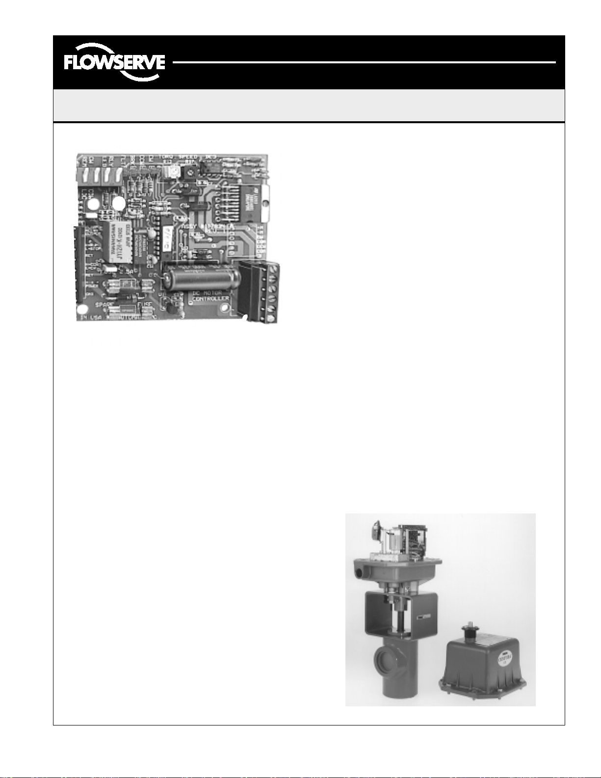
DC Motor Controller Board
Features and Benefits
The Controller Board addition to a DC Motor Actuator offers:
1. Adjustable, fault current motor protection.
2. Two, 2-wire signal inputs: direction and dynamic brake.
3. Control of 12 and 24 VDC motor actuators.
4. Adjustable torque and speed control.
5. PCB plugable terminal blocks for interface wiring.
6. Solid-state microprocessor based motor driver
replaces relays.
7. An on-board glass fuse, field replaceable.
8. Four (4) status LED indicators: CW and CCW
direction, BRAKE set, and FAULT latch set.
9. Local switches provide for alarm and LED
disabling to conserve power consumption.
10. Reverse polarity protection.
11. Field settable failure mode.
Centura CE Series Actuators are designed with:
Introduction
Using state-of-the-art microprocessor technology, the
DC Motor Controller Board provides protection and
operational advantages over "hardwired" DC motor
actuators. A current sensing circuit continuously
monitors motor operating conditions. When stalled or
abnormally high motor current exists, the controller
automatically shuts power off to the motor. Current
sensing protects not only dc motor brushes from
destruction, but also protects power supplies during
fault conditions, including solar recharging systems
from extreme battery discharge. A fault latching circuit
will maintain this off status until an input direction
change is detected to reset the latched controller for
normal operation.
1. Captive cover bolts.
2. Manual override with integral motor power cutout
switch.
3. Quick set, end-of-travel cams with micro precision
adjustment screws.
4. Standard aluminum housing, with polyester coating for
superior corrosion resistance, rated for NEMA 4, 4X, 7,
and 9 applications.
5. Options include: a manual override hand wheel, up to
four (4) extra SPDT switches, and an extra conduit entry.
Flowserve’s design and manufacturing expertise includes
Autobrakit mounting hardware for convenient adaptation of
Centura Series Actuators to all types of valves and dampers.
Consult your Flowserve Representative today for your
actuating needs.
The current sensing circuit and initial setup procedures
use on-board local control switches and adjustments.
Local control and LED status indicators ease calibration
by eliminating special test measurements and control
room activity. Remote operations are accomplished by
2-wire switching from PLC's, dry contact relays or
switches. A 2-wire "brake" control is optionally used for
mid-stroke positioning.
The AUTOMAX DC Motor Controller Board conveniently
mounts inside Centura CE Series Electric Actuators. The
CE actuators' unique housing design satisfies NEMA 4,
4X, 7, and 9 ratings simultaneously, providing indoor
and outdoor protection in industrial applications
including gas and oil, pulp and paper, oil patch sites,
and chemical processing.
LME0005-1 (AUTO-43) 07/03
©
2003, Flowserve Corporation, Printed in USA
An automated choke valve with Autobrakit mounting hardware
Page 1 of 4
Page 2

Automax Valve Automation Systems
3-Position Control/Dribble Control
Installation, Operation and Maintenance Instructions
Flowserve Corporation 1350 N. Mountain Springs Parkway 1978 Foreman Dr.
Flow Control Division Springville, Utah 84663-3004 Cookeville, TN 38501
www.flowserve .com Phone: 801 489 8611 Phone: 931 432 4021
SR Limit Switch Method
Installation and Operating Instructions
This instruction set contains information for proper setup
of the Controller Card. Additional actuator mounting and
maintenance information may be found in appropriate
instruction sets.
Note:
If CCW limit cam engages limit switch before
attaining desired position, set BRAKE ON/OFF
switch to ON, adjust cam to disengage switch, and
continue with Step 6.
Automax CE Electric Actuators are factory adjusted for 90
degree operation and shipped, as viewed from the motor
side, in the full clockwise position.
Control Input Connections
1. Connect remote directional input wiring to
H=CW/L=CCW and RET terminals (TB1 pins 5
and 6), per Page 3 input details.
2. Connect remote braking input wiring, when
required, to the H=RUN/L=STOP and RET
terminals (TB1 pins 3 and 4), per Page
3 input details.
Initial Setup for Valve Port Alignment
1. Set the six (6) on-board local control
switches to BRK, LOCAL, LOCAL, CW, LED, RLY.
2. Ensure CW limit cam has engaged CW limit
switch with valve in full clockwise position.
3. Connect proper DC voltage supply to +++/
POWER and RET terminals (TB1 pins 7 and
8), noting proper voltage level and polarity.
Label on motor gearbox identifies proper
actuator voltage rating. Voltage input is diode
protected against + / - reversal, but actuator
will not respond if polarity is reversed.
4. Apply power and observe LED CW is blinking
when BRK / RUN is in run.
5. Set CW/CCW switch to CCW, and observe
LED CCW is lit, and LED CW is out. Motor
begins to turn, and valve begins to open.
Note: If LED F (fault) lights, adjust I SENCE
pot 1/8 turn clockwise, clear fault by turning
BRK on or by toggling direction control switch.
8. Set CW/CCW switch to CW, BRAKE ON/OFF
switch to OFF, and observe CW limit switch/cam
stops motor when valve reaches proper
clockwise position.
Note:
Set BRAKE ON/OFF switch to ON if limit cams
require adjustment. This eliminates actuator from
rotating during cam/switch adjustments.
9. Repeat clockwise and counterclockwise position
checks and ensure valve limits are correct.
Speed and Current Limiting Adjustments
TORQUE and I SENSE adjustments are dynamic settings
that vary by application and affect CW and CCW directions
equally. Toggle CW/CCW switch to cycle actuator while
making adjustments.
1. Set the TORQUE (speed) adjustment
counterclockwise, when needed, to slow
actuator stroke speed.
2. Setting the I SENSE (current limiting)
adjustment counterclockwise will reduce the
amount of motor current needed to trigger the
fault latch circuit. The I SENSE adjustment should be
set to allow CW/CCW motor reversals "on-the-fly".
Note:
Check to ensure adequate power is
available at times of normal high current conditions.
Verify the I SENSE adjustment allows motor to
operate "into" and "off of" valve seat.
3. Set the two (2) on-board LOCAL/REMOTE
switches to REMOTE. This will disable CW/CCW and
BRAKE ON/OFF local switches, while transferring
control to remote inputs connected at TB1.
4. Verify proper operation from the control room.
6. Set BRAKE ON/OFF switch to ON and observe
motor stops and LED BRK is on. Set BRAKE
ON/OFF switch to OFF and observe motor
turning.
7. Set BRAKE ON/OFF switch to ON when
valve reaches final counterclockwise position, and
set CCW limit cam to engage CCW limit switch.
LME0005-1 (AUTO-43) 07/03
©
2003, Flowserve Corporation, Printed in USA
5. Set LED switch to "OFF" for power savings, if desired.
Page 2 of 4
Page 3

Automax Valve Automation Systems
3-Position Control/Dribble Control
Installation, Operation and Maintenance Instructions
Flowserve Corporation 1350 N. Mountain Springs Parkway 1978 Foreman Dr.
Flow Control Division Springville, Utah 84663-3004 Cookeville, TN 38501
www.flowserve .com Phone: 801 489 8611 Phone: 931 432 4021
SR Limit Switch Method
Interface Wiring Control Input Configurations
A. PLC Open Collector Outputs are also known
as discrete digital ouputs. The "output on"
state causes a zero volt measurement at TB1
signal and RET terminals. The "output off" state voltage
will equal approximately 5.00V at TB1 terminals.
PLC TTL OUTPUT CONFIGURATION
OPEN COLLECTOR (O.C.)
C. 3-Way Manual Switching is similar to dry-
contact switching, as discussed above in
Step B, but allows one single pole, 3 position
manual switch to control direction and braking
at a remote jogging station.
B. Dry-Contact Switching, while using manual or
relay control, does NOT require external
voltages to be applied to contacts. When
contacts are closed, the voltage between the
TB1 signal and RET terminals will equal zero volts.
Open contact voltage will equal approximately
5.00V at TB1 terminals.
DRY CONTACT SWITCHING
SPST SWITCH OR RELAY
ABOVE DIAGRAMS REPRESENT JUMPERS J3 & J4 ON LEFT TWO POSTS
DC Motor Controller Board Layout and Motor Interface Wiring
POSITION 1: BRAKE OFF, CW ROTATION
POSITION 2: BRAKE ON, NO ROTATION
POSITION 3: BRAKE OFF, CCW ROTATION
LME0005-1 (AUTO-43) 07/03
©
2003, Flowserve Corporation, Printed in USA
Page 3 of 4
Page 4

Automax Valve Automation Systems
3-Position Control/Dribble Control
Installation, Operation and Maintenance Instructions
Flowserve Corporation 1350 N. Mountain Springs Parkway 1978 Foreman Dr.
Flow Control Division Springville, Utah 84663-3004 Cookeville, TN 38501
www.flowserve .com Phone: 801 489 8611 Phone: 931 432 4021
SR Limit Switch Method
Troubleshooting Guide
1. No LED indicators lit:
A. DC Power Supply not on
B. On-board fuse blown, check for proper
power polarity and voltage level at
+++/POWER and GND (TB1 pins 7 and
8), replace fuse.
C. LED switch set to OFF
2. Actuator is not responding to remote inputs:
A. Ensure on-board local control switches
LOCAL/REMOTE are set to REMOTE.
B. Check polarity of signaling terminal
wiring, and proper voltage measurements,
see Page 3, Input Configurations.
C. Check LED F (fault) latch set, adjust
I SENSE adjustment as required,
following instructions on Page 2.
D. Check that jumpers J3 & J4 are both on
left two posts or both on right two posts
as desired. See diagram on Page 3 for directions.
DC Motor Actuator Specifications
DC Motor System 12V 24V
Supply Voltage (maximum) 14V 28V Volts
Remote Signal (18AWG) 5000 5000 ft.
Cycle Time*, (min/max adj)
CE2B, CE2C 6-14 6-14 sec.
CE4B, CE4C 8-20 8-20 sec.
CE7B, CE7C 15-31 15-31 sec.
CE1B, CE1C 20-42 20-40 sec.
CE5B, CE5C 32-60 30-60 sec.
Supply Currents (typ.)
Controller Board 10** 15** mA
DC Motor (full load) 1.60 0.9 A
I Sense Adj. (max) 2.0 2.0 A
Operating Temperature -40 to 160 Deg. F
(-40 to 70 Deg. C)
* - Times are approximate under no load conditions and
may vary slightly under actual operating conditions.
** - Board options set at minimum current draw.
How to Order
(Select from each column)
CENTURA Series Actuator - CE Extras
Size Motor Switches Options Conduit (can add more than one)
250 in-lbs -2 12 VDC (without brake) -B One extra -1 DC Motor Controller -DA Right Hand -Blank Epoxy Coating -E
400 in-lbs -4 24 VDC (without brake) -C Two extra -2 4-20mA Transmitter -TX Both Left & Right -X Heater & Stat -H
700 in-lbs -7 Three extra -3 0-135 Ohm Potentiometer -P1 Manual Handwheel -Z
1,000 in-lbs -1 Four extra -4 0-1000 Ohm Potentiometer-P2
1,500 in-lbs -5 0-5000 Ohm Potentiometer-P3
Weight CE2, CE4, CE7, CE1 = approx. 18 lbs., CE5 = approx. 20 lbs.
Ordering Example: Automax CENTURA Series Electric Rotary Actuator capable of 400 in-lbs. torque, to operate on 12 VDC with DC Motor
Controller would read: CE4BDA
*Flowserve can supply special mounting on the bottom of the CENTURA Series actuators to direct couple to many common valve lines.
**No mechanical solenoid brake as supplied on AC Actuators.
LME0005-1 (AUTO-43) 07/03
©
2003, Flowserve Corporation, Printed in USA
**
0-10K Ohm Potentiometer -P4
0-1000, 0-10K Dual Pot -P6
Page 4 of 4
 Loading...