

Page 1
Worcester Actuation Systems
WCAIM2050
DC AF-17 Electronic Positioner
Installation, Operation and Maintenance Instructions
A. GENERAL
This supplement to the AC AF-17 IOM covers the DC AF-17 circuit
board. This supplement will cover those features of the DC board
that are different than the AC version.
There are two major differences between the AC and DC versions of
the AF-17 board. The first of these is the fact that the DC AF-17
board is plug connected to the actuator terminal strip as opposed to
being wired directly into the terminal strip. This makes it much
easier to install or remove the circuit board for adjustments, repairs,
etc. The baseplate in the 75 Series Actuator is wired differently for
the DC versus the AC AF-17 board, and the two are not
interchangeable. The DC baseplate has connector plug assemblies
wired into the terminal strip, and the limit switches are wired into the
connector plug assemblies. The second major difference is that this
board is powered directly with DC voltage versus AC voltage. This
board can be powered with either 12 or 24 volts DC with no changes
needed to the circuit board. The only caution in this regard is that
the proper motor(s) be used for the voltage applied.
IMPORTANT: All of the cautions and notes in the AC AF-17 IOM
should be read prior to installing this board in a 75 Series Actuator.
B. CAUTIONS
PLEASE READ THIS SECTION
1. Power Rating
At this time, the DC AF-17 board has been approved for use in
size 10 through 23 75 Actuators only.
2. NOTE: Fusing Protection for input circuits as found on earlier DC
boards only.
Earlier version of DC AF-17 boards are protected with a 62 mA
fuse (F2) and a 12 volt zener diode (CR18) installed across the
input circuit. These two devices in combination are designed to
protect the CMOS chip from both an overvoltage condition and
reverse polarity of the input signal. For earlier version using a
4-20 mA signal input circuit, the signal input impedance of the
AF-17 board is approximately 220 ohms which means that it
only takes about 4.5 volts to drive 20 mA through the input
circuit. If your current source is capable of outputting 12 volts
or more, it may be necessary to place a ¹₄ watt resistor in
series with the current loop to drop the excess voltage,
otherwise you might find that you keep blowing the input
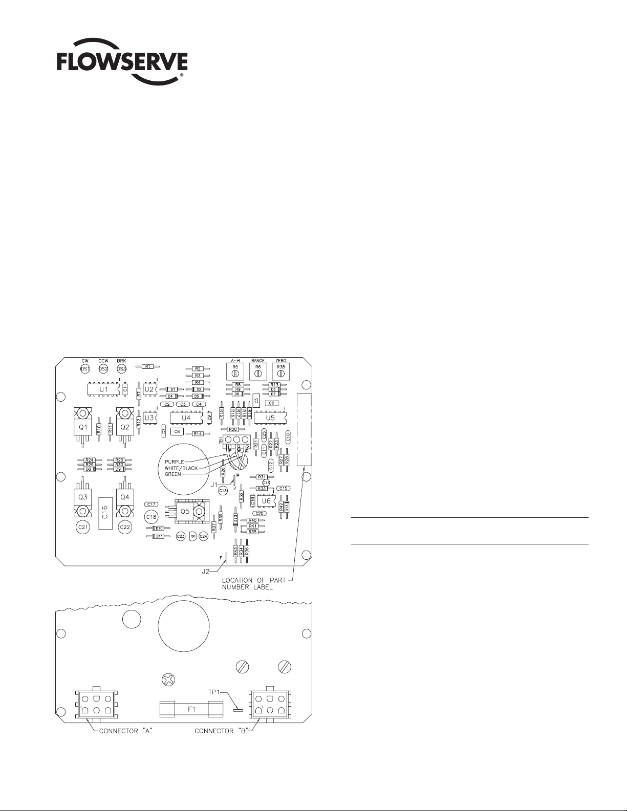
Use or value of components R13, R26, R34, R35, R36, J1 and J2
will vary depending on circuit board input.
Figure 1 – 12 and 24 VDC Positioner Circuit Board
Page 2

protection fuse. This is most likely to happen when you initially
turn on your current source, i.e., before it starts regulating its
output current. For example, let's say you measure an open
circuit voltage from your current source of 24 volts. Apply the
following formula to determine the value of the resistor to be
added in series with the current loop:
R = [ 24 volts - ( .05 × 220 ohms )] /.05
This calculation may yield a resistor value that is not a common
standard value. Select a resistor of the next higher standard
value (i.e., if your calculation result is a value of 260 ohms, as in
the above example, then pick the next higher standard resistor
value which in this case would be 270 ohms). This will ensure
that enough voltage will get dropped across the added resistor
at 50 mA, to prevent the zener diode from turning on and
causing the fuse to blow. If there are other devices in the current
loop such as a chart recorder or digital readout, then their input
resistances must be added to the input resistance of the AF-17
board (in the above formula, 220 ohms would be replaced by the
total loop resistance). If the calculation results in a zero or a
negative resistance value, then no additional series resistor is
needed. The fuse (F2) used in the input circuit is a Littlefuse
PICO II very fast acting fuse rated at 62 mA. There is a spare
fuse located near the top edge of the circuit board between the
two connectors.
All DC versions of the AF-17 board use a standard 1¹₄" 250 volt,
3 amp fuse (F1) to protect the circuit board and the power
source in case of a fault in the H-bridge circuit on the circuit
board. The H-bridge circuit is the DC polarity and power
switching circuit for the DC motor(s).
CAUTION: It is important that the DC voltage power source be
connected properly to the actuator's terminal strip. Terminal
one (1) of this strip is to have the negative wire connected to
it. Terminal two (2) is to have the positive wire connected to it
(See Figure 3 on page 4.). As stated above, earlier versions of
the board have a diode and a fuse installed to prevent
damage, as in the case of reverse voltage polarity, but if the
diode happens to be defective, damage could be done before
the fuse blows.
NOTE: All wiring to terminal strip should be inserted only to midpoint of terminal strip.
3. Floating Input Signal
The AF-17 board has been designed to receive a floating current
input signal as standard from the factory. This allows several
pieces of equipment to be operated from the same current loop
while at the same time remaining electrically independent of
each other. A floating input signal means that the current input
signal should not be referenced to the circuit board ground. This
is especially important with DC powered circuit boards. The
board power source must have a ground independent from that
of the signal source.
4. Quadrants of Operation (Refer also to Page 4 of AC AF-17 IOM)
The AF-17 board can be set up in several ways for normal
operation. The board is designed to control in 90° quadrants
only. The number of quadrants over which the board will control
is determined by the number of teeth on the feedback
potentiometer pinion gear. The adjustment trimpots on the board
were not set up to reduce actuator travel for a 4 - 20 mA input
span. For example, trying to adjust the board such that 4 mA is
closed and 20 mA is only 60% open is just not possible with the
standard setup.
The standard setups are:
1) 4 mA for full clockwise rotation – i.e., 0° and 20 mA for full
counterclockwise rotation – i.e., 90° or 180°.
2) Split range where 4 mA would be full clockwise and 12 mA
would be full counterclockwise or 12 mA would be full
clockwise and 20 mA would be full counterclockwise.
3) Each of the above standard setups can also be made reverse
acting.
4. Feedback Potentiometer Calibration
Quite often when we receive an actuator for repair at Flowserve
we find that the only thing wrong with the unit is that the
feedback potentiometer is out of calibration. It is very important
that the feedback potentiometer be properly calibrated for
correct operation of the positioner board. It is also very
important that the actuator shaft not be rotated out of the
quadrant for which the feedback potentiometer has been
calibrated. Whenever you have a problem with positioner
calibration, always check the feedback potentiometer calibration
first. This must be done with no power applied to the circuit
board. If the actuator is in the full clockwise position, check the
resistance between the purple and white/black potentiometer
leads. The reading should be 80-90 ohms. If it is not, rotate the
face gear until the proper reading is achieved. NOTE: It is not
necessary to loosen or remove face gear snap ring to rotate
gear, it is a friction fit. If for any reason the snap ring(s) are to
be removed, do not over stretch them; use minimum opening to
allow them to slip over the gear. If the actuator happens to be in
the full counterclockwise position then check the resistance
between the green and white/black potentiometer leads. If
necessary, adjust the face gear for an 80-90 ohm reading.
C. INSTALLATION OF DC AF-17
1. General
If the actuator was purchased with the DC AF-17 positioner
board factory installed, proceed to section 4.0.
2 DC AF-17 Electronic Positioner WCAIM2050
Flow Control Division
Worcester Actuation Systems
Page 3

a. Check kit for parts:
b. Tools Needed:
¹₄" nut driver, ¹₈" screwdriver, needle nose pliers, ¹₁₆" Allen
wrench (cams and spur gear), Volt/Ohmmeter (checking
feedback potentiometer resistance, voltages, incoming
control signal).
2. Feedback Potentiometer Connections
The feedback potentiometer is connected to the circuit board at
the terminal block on the DC AF-17 circuit board by leading the
feedback potentiometer wires up through the ⁵₁₆" hole near the
terminal block; green wire to terminal 3, white/black wire to
terminal 2, and purple wire to terminal 1. If a dual feedback
potentiometer is installed in the actuator, then the front or ‘A’
section of the feedback potentiometer is wired to the circuit
board as mentioned above and the back or 'B' section of the
feedback potentiometer is wired to the actuator terminal strip
with the green wire connected to terminal 7, the white/black wire
connected to terminal 8, and the purple wire connected to
terminal 9. Be certain to route the wires such that they cannot
become caught in either the switch arms or the feedback
potentiometer drive gears. NOTE: Voltage limit of “B”
potentiometer is 30 volts maximum.
3. Mounting Circuit Board:
For 12/24 VDC 10-23 Size Electric Actuators: (See Figures 2 and 3).
1) Pre-tap circuit board bracket holes with the self-tapping
circuit board mounting screws (item 5). Remove the outside
corner motor screws and mount the brackets to the
appropriate spacers using the self-tapping spacer/bracket
mounting screws (item 8) being careful, to avoid stripping
the threaded holes in motor base. The longer bracket is
mounted to the right side of the actuator when facing the
terminal strip.
NOTE: The proper length spacers and screws must be used
based on the actuator size:
10,12 size actuators having single motor will use the two
shortest spacers on motor side and two intermediate length
spacers on the opposite side, and four of the shorter
spacer/bracket mounting screws.
20,22 size actuators have two motors and use four of the
shortest length spacers and four of the shorter
spacer/bracket mounting screws.
23 size actuators also have two motors but will use four of
the longest length spacers and four of the longest length
spacer/bracket mounting screws.
2) Once these screws and brackets are firmly secured, firmly
tap the motor stators with a plastic-faced hammer to force
realignment of the motor bearings.
3) Loosen all terminal strip screws and install the A and B
connector cable assemblies into the actuator terminal strip.
See figure 3 (next page) for proper wiring of cable
assemblies to terminal strip. Wire routing is important.
Ensure that wiring is not pinched and is not touching any
moving parts such as cams or switch arms.
4) Assemble circuit board into actuator. Slide rubber grommets
onto insulating board. Put nylon washers under heads of
self-tapping screws (Five screws will be used to install the
circuit board onto the brackets).
5) Place the circuit board over the brackets with the insulating
board between the circuit board and the mounting brackets.
Loosely tighten the four screws securing the board and
insulator. Use a nylon washer and a rubber grommet on the
self-tapping screw securing the right front corner of circuit
board (as you face the terminal strip). Place the rubber
grommet between the circuit board and the mounting
bracket. Tighten all the mounting screws so that the
grommets are about half compressed.
6) The baseplate in the DC actuator is wired differently than
that in the AC actuator. Once the circuit board is
mechanically installed, it is then necessary to plug in the two
connector cables from the baseplate to the circuit board. The
connector with the blue, yellow, and brown wires (plus three
additional wires) is plugged into the circuit board connector
next to the main power fuse. The connectors are polarized
so that thay are plugged correctly (i.e., pin 1 to pin 1, etc.).
D. CALIBRATION
Refer to AC AF-17 IOM Section 4.0
NOTE: LED designations DS1, DS2, and DS3 on DC circuit board are
equivalent to LD2, LD1, and LD3 on AC circuit board respectively.
E. MISCELLANEOUS
Refer to the AC AF-17 IOM for all other pertinent information.
COMMON PARTS FOR SIZES 10-23
WCAIM2050 DC AF-17 Electronic Positioner
Flow Control Division
Worcester Actuation Systems
Qty. Name
1 Circuit Board
Subassembly
1 Pot Kit
Subassembly
1 Insulating Board
1Wiring Label – Cover
5Washers (Nylon)
1 Instruction Manual
5Grommets (Rubber)
5 Cable Ties
5 Mounting Screws
1 Bracket – Right
(Long) (Circuit
Board)
Qty. Name
1 Nameplate – Circuit
Board
1 Bracket – Left
(Short)
1 Nameplate – Base
10 Spacers (Bracket)
(Various Lengths)
1 Closed End Splice
8 Mounting Screws
(Bracket/Spacer)
(Various Lengths)
2 Connector Cable
Assemblies (One 'A'
and One 'B'
Assembly)
Page 4

Flowserve Corporation has established industry leadership in the design and manufacture of its products. When properly selected, this Flowserve product is designed to perform its intended function
safely during its useful life. However, the purchaser or user of Flowserve products should be aware that Flowserve products might be used in numerous applications under a wide variety of industrial
service conditions. Although Flowserve can (and often does) provide general guidelines, it cannot provide specific data and warnings for all possible applications. The purchaser/user must therefore
assume the ultimate responsibility for the proper sizing and selection, installation, operation, and maintenance of Flowserve products. The purchaser/user should read and understand the Installation
Operation Maintenance (IOM) instructions included with the product, and train its employees and contractors in the safe use of Flowserve products in connection with the specific application.
While the information and specifications contained in this literature are believed to be accurate, they are supplied for informative purposes only and should not be considered certified or as a guarantee of
satisfactory results by reliance thereon. Nothing contained herein is to be construed as a warranty or guarantee, express or implied, regarding any matter with respect to this product. Because Flowserve
is continually improving and upgrading its product design, the specifications, dimensions and information contained herein are subject to change without notice. Should any question arise concerning
these provisions, the purchaser/user should contact Flowserve Corporation at any one of its worldwide operations or offices.
For more information about Flowserve Corporation, contact www.flowserve.com or call USA 1-800-225-6989.
FLOWSERVE CORPORATION
FLOW CONTROL DIVISION
Worcester Actuation Systems
5114 Woodall Road
P.O. Box 11318
Lynchburg, VA 24506-1318 USA
Phone: 434-528-4400
Facsimile: 434-845-9736
www.flowserve.com
© 2003 Flowserve Corporation, Irving, Texas, USA. Flowserve and Worcester Controls are registered trademarks of Flowserve Corporation. WCAIM2050 10/03 Printed in USA
Flow Control Division
Worcester Actuation Systems
ITEM DESCRIPTION
1 Circuit Board
Subassembly
2 Insulating Board
3 Bracket – Right (Long)
4Grommet – Rubber
5 Mounting Screws
(Circuit Board)
6Washer-Nylon
7 Bracket-Left (Short)
8 Mounting Screws
(Bracket)
9 Spacer (Bracket)
Figure 2
Figure 3
Actuator Base
This Motor Used Only With
20 Through 23 Size Actuators
Potentiometer Kit Subassembly
 Loading...