

Page 1
Issue Date: 10/06
GESTRA Steam Systems
Instructions for Installation and Maintenance
Cooling-Water Control Valves Gestramat
CW 41, CW 41/4
PN 16, DN 25 – 100 mm (1 – 4")
Description
The cooling-water control valves type CW are direct-acting
proportional controllers for installation in cooling water or
brine return lines. They ensure that the cooling-water outlet
temperature is maintained at a preset value, calculated for
the process requirements.
When using cooling-water control valves, higher temperatures are possible than with an uncontrolled process.
As a result of the larger heat absorption by the coolingwater or brine, cooling-agent and energy consumption
are reduced.
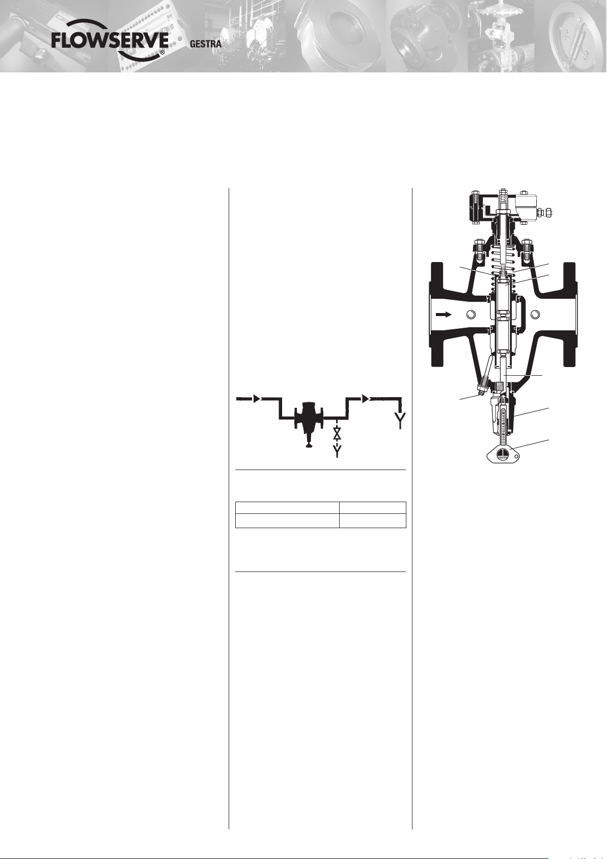
The regulator of the CW 41 consists of one, two or three
thermostats 3 (depending on the valve size) mounted in series
within a double-seat valve cone 2. The upper cone closes
tight whilst the lower one is designed with a tolerance
to form a leak passage (“s” cone), or the leak passage is
formed by a borehole in the cone (“r” cone).
The thermostats 3 contain an elastomer thermal expansion
material (“n” and “k” thermostats) or wax (“w” thermostat).
Under the influence of heat the volume of the thermostats
increases, projecting a pin which is included in the
thermostat body.
The lift of the thermostats is transmitted to the valve cone
via the pin of setting device 6, supporting the thermostats.
With rising cooling-water outlet temperature, the valve
cone is moved in the opening direction against the force
of the spring. When the temperature drops again the valve
cone is moved by the spring 7.1 in the closing direction.
With the aid of setting key 11 that can be removed and fits
all valve sizes, the position of the setting pin can be varied
to obtain higher or lower cooling-water outlet temperatures
(see “Temperature Adjustment”).
Even if the valve is closed, a continuous bleed flow ensures
a sensitive response. The bleed flow can be increased by
screwing setting screw 7.6 to the right (e.g. in the case of
a long line between heat exchanger and CW).
Installation
1. Screw pressure gauge (item 15) into the inlet (point A
in figure opposite) and thermometer (item 16) into the
outlet (point B in figure opposite). To avoid damaging
these instruments tighten them only at the hexagon
using a spanner (A.F. 14 and 19 mm).
2. Always install CW 41 in the cooling-water return line as
close as possible to the heat exchanger. Flow is in the
direction of arrow. Recommended position: in horizontal
lines, setting device 6 pointing downwards.
With free drainage the CW should be installed so that
it will not run empty, so as to prevent the formation of
deposits. If there is the danger of freezing it might be
useful to provide a drain valve in the water pocket (see
schematic diagram below). If necessary, the valve can
be emptied by unscrewing setting device 6.
Note: When the CW valve is closed, the cooling zone is
under full pump pressure.
Pressure / Temperature Rating
Max. service pressure 16 barg (230 psig)
Max. differential pressure 6 bar (85 psi)
Temperature ratings see “Adjustment Table”, page 4.
Differential pressure = inlet pressure minus outlet
pressure.
Product Range A4
CW 41
CW 41/4
2
R ¼"
A
7.6
A = Connection for pressure gauge
B = Connection for thermometer
CW 41 DN 40, 50
7.1
3
R ¼"
B
Setting pin
6
11
Maintenance
The CW 41 does not require any particular maintenance.
If there is the danger of freezing, the valve should be
emptied.
Page 2

Parts List CW 41
Item No. Description Stock code Number Material Hints
1
1.1
2 Valve cone:
2.1 O-ring
3 Thermostat complete:
4 Retaining ring 010332 1 S.S. (1.4034) DIN 472 21.1 x 1
5 Gasket 010333 1 DIN 7603 Steel A 26 x 31 mm
6
7.1 Spring
7.2 *) Gasket
7.3 Cover – 1 S.G. iron (0.7043) no spare part
7.4 Stud bolt
7.5 Nut
7.6 Setting screw 004965 1 S.S. (1.4122)
7.8 “Seal-lock” nut 004800 1 8.8 M 8
7.9 *) Gasket 000992 4 DIN 7603 – S.S. (1.4301 N) A 14 x 18
7.10 Plug 085289 4 Steel (1.0501) ¼" BSP
11 Adjusting key 004962 1 Brass (2.0401)
15 Pressure gauge 1) 004704 1
16 Thermometer 1) 184596 1 Measuring range: –30 °C to 100 °C
1
) With “k” thermostat use:
– Setting device complete with extension (stock code 031135)
– Pressure gauge with extension (stock code 031154) and
– Thermometer with extension (stock code 184598)
*) Parts subject to wear (stock keeping recommended)
Body
Seat
“r” cone complete
“s” cone
“w” thermostat
“n” thermostat
“k” thermostat
Setting device complete 1)
Threaded bush
Gasket
DN 25 mm (1")
DN 40, 50 mm (1½, 2")
DN 80, 100 mm (3, 4")
DN 25 mm (1")
DN 40, 50 mm (1½, 2")
DN 80, 100 mm (3, 4")
DN 25 mm (1")
DN 40, 50 mm (1½, 2")
DN 80, 100 mm (3, 4")
DN 25 mm (1")
DN 40, 50 mm (1½, 2")
DN 80, 100 mm (3, 4")
DN 25 mm (1")
DN 40, 50 mm (1½, 2")
DN 80, 100 mm (3, 4")
DN 25 mm (1")
DN 40, 50 mm (1½, 2")
DN 80, 100 mm (3, 4")
DN 25 mm (1")
DN 40, 50 mm (1½, 2")
DN 80, 100 mm (3, 4")
DN 25 mm (1")
DN 40, 50 mm (1½, 2")
DN 80, 100 mm (3, 4")
DN 25-50 mm (1-2")
DN 80, 100 mm (3, 4")
DN 25-50 mm (1-2")
DN 80, 100 mm (3, 4")
–
–
184283
184288
184292
004940
004980
030000
030092
030093
031787
004941
030040
030042
004953
031837
010501
004950
004981
030001
184372
184373
184374
010135
010140
010514
013123
1
2
S.G. iron GGG-40.3 (0.7043)
S.S. (1.4122 / 1.4401)
no spare part
no spare part, inerference-fit
1 Cast brass (2.0290)
1 Cast brass (2.0290)
1 EPDM for “r” cone only
1
2
3
1
2
3
1
Body:
Brass (2.0380)
Pin:
Austenitic satinless steel
(1.4571)
2
3
1
1
1
Brass (2.0380) / S.S.
Steel (1.0356)
DIN 7603 Steel
A 40 x 47
{ 100 mm (3, 4")
only for DN 80,
1
1
Austenitic stainless steel (1.4571)
1
1
1
Graphite/CrNi
1
4
6
4
6
DIN 939 – 5.6
DIN 939 – 5.8
DIN 934 – 5
DIN 934 – Steel (1.7258)
45.5 x 75 x 1.0
55.5 x 90 x 1.0
92.5 x 136 x 1.0
M 8 x 22
M 10 x 25
M 8
M 10
Measuring range:
0 – 6 barg (0 – 85 psig)
Note: CW 41 for usual industrial cooling water.
CW 41/4 for salt water, ammoniacal water and chlorinated hydrocarbons.
Page 3

7.5
7.4
7.9 + 7.10
2.1
7.8
7.6
Dismantling
Exchange of Valve Cone / Thermostat
1. Isolate the valve from pressure. Shut off feed line and
7.3
7.2
2
1
A B
7.1
3
7.9 + 7.10
1.1
4
5
6
in the case of back pressure also return line.
2. Remove nuts
Attention: Spring 7.1 is under tension!
Reduce tension by turning adjusting key
Be careful when loosening nuts. Remove cover 7.3,
and take out spring 7.1.
3. Turn adjusting key
felt to push valve cone 2 upwards.
4. Take out valve cone
To exchange thermostats 3 remove retaining ring 4.
(Number of thermostats:
DN 25 mm (1") = 1 off;
DN 40, 50 mm (1½, 2") = 2 off;
DN 80, 100 mm (3, 4") = 3 off.)
The setting device 6 is provided with a righthand thread.
Normally, the setting device need not be dismantled.
Reassembly in reverse order.
Take care that sealing surfaces are clean, replace gasket
7.2. Valves with “r” cone: Ensure that O-ring 2.1 is un-
damaged, replace if necessary.
Torques required for tightening nuts 7.5 at room temperature
DN 25, 40, 50 mm (1, 1½, 2") 15 Nm
DN 80, 100 mm (3, 4") 25 Nm
7.5.
11 to the left.
11 to the right until a resistance is
2 from above.
Tools Required
Spanners for items
7.5 DN 25, 40, 50 mm (1, 1½, 2") A.F. 13 mm
DN 80, 100 mm (3, 4") A.F. 17 mm
6 A.F. 32 mm
15 A.F. 14 mm
16 A.F. 19 mm
Shown
11
CW 41 DN 40, 50 mm (1½, 2")
A = Connection for pressure gauge
(item 15), ¼" BSP
B = Connection for thermometer
(item 16), ¼" BSP
Parts List CW 41/4 (for parts differing from those of CW 41)
Item No. Description Stock code Number Material Hints
2 Valve cone:
For “r” cone only:
O-ring of FKM (Item No. 2.1)
DN 25 mm (1") No. 031151
DN 40, 50 mm (1½, 2") No. 031152
DN 80, 100 mm (3, 4") No. 031788
Measuring range:
0 – 6 barg (0 – 85 psig)
“r” cone complete
“s” cone
3 Thermostat complete:
“w” thermostat
“n” thermostat
“k” thermostat
6
15
15.1
16
16.1
Setting device complete
with extension
Pressure gauge with extension
Pressure gauge, water-proof
Thermometer with extension
Thermometer 105 mm long
DN 25 mm (1")
DN 40, 50 mm (1½, 2")
DN 80, 100 mm (3, 4")
DN 25 mm (1")
DN 40, 50 mm (1½, 2")
DN 80, 100 mm (3, 4")
DN 25 mm (1")
DN 40, 50 mm (1½, 2")
DN 80, 100 mm (3, 4")
DN 25 mm (1")
DN 40, 50 mm (1½, 2")
DN 80, 100 mm (3, 4")
DN 25 mm (1")
DN 40, 50 mm (1½, 2")
DN 80, 100 mm (3, 4")
184348
184351
184352
030984
030987
030990
184427
184428
184429
031135 1 S.S. (1.4305 / 1.4104)
031154
033779
184598
184597
1 Satinless steel (1.4312)
1 Satinless steel (1.4312)
1
2
3
1
2
3
1
2
3
1
1
1
1
Body and Pin:
Austenitic satinless steel
(1.4571)
Extension: S.S. (1.4104)
Extension: S.S. (1.4104) Measuring range: –30 °C to 100 °C
Page 4

Cooling-Water Control Valves
Gestramat
CW 41, CW 41/4
PN 16, DN 25 – 100 mm (1 – 4")
Temperature Adjustment
GESTRA cooling-water control valves CW 41...– exact
designation see name plate – can be preset with the
adjusting key to the desired cooling-water outlet tem
perature. The graduations on the key correspond to the
temperatures indicated in the adjustment table.
The required outlet temperature is adjusted after start-up.
Turn adjusting key ¼ to ½ turn at a time. (Remember that
one key can be used for all CWs).
The outlet temperature is indicated by the thermometer.
Note that the reaction period of the plant to an adjusted
temperature might be 10 to 50 minutes.
Setting device of CW 41
Read graduation at this edge
Insert key into setting device
until it engages
Increase in Bleed Flow
When supplied, setting screw 7.6 is set so that it does not
touch valve cone 2. To adjust an additional bleed flow with
screw 6 proceed as follows:
1. Turn adjusting key
into closed position. The pressure gauge 15 will then
indicate the full service pressure.
2. Turn setting screw
gauge indicates a pressure drop which signifies that
the opening point of the valve is reached.
3. Adjust additional bleed flow. Normally, ¼ to ½ turn will
suffice. One complete turn to the right corresponds to
a valve lift of approx. 1.2 mm.
11 to the left to bring valve cone 2
7.6 to the right until the pressure
Adjustment table for CW 41 wr, ws, nr, ns, kr, ks
Desired outlet temperature in °C
DN 25 mm (1") DN 40, 50 mm (1½, 2") DN 80, 100 mm (3, 4")
wr
ws
-
68 114 79 41 72 37 36 58 23 –––– 12 –––
54 100 65 38 65 30 34 53 18 ––––––––––
47 82 51 36 58 23 33 49 14 –––– 10 –––
41 72 37 33 51 16 31 44 09 ––––––––––
36 58 23 31 44 09 30 39 04 –––– 8 –––
31 44 09 28 37 02 27 35 00 ––––––––––
25 30 –05 25 30 –05 25 30 –05 –––– 6 –––
18 16 –19 20 23 –12 20 25 –10 ––––––––––
Malfunction
Reasons and Remedies
1. Discontinuous operation, intermittent opening and
closing of valve cone, unstable control position
The reason may be that the cooling-water control
valve is installed at quite a long distance from the heat
exchanger.
Remedy: Install the CW directly downstream of the heat
exchanger or, if this is not possible, increase the bleed
flow.
2. Setting device hard to turn or blocked
This may be caused by foreign bodies, dirt or calcium
deposits in the valve body.
Remedy: Clean cooling-water control valve and mount
a strainer upstream of valve. Calcium deposits can
only be avoided by water softening or possibly a lower
discharge temperature adjustment might help.
nr
ns
03 –32 16 –19 21 –14 –––– 4 –––
kr
ks
wr
ws
68 114 79 47 86 51 –––– 18 –––
60 107 72 45 81 48 ––––––––––
54 100 65 43 77 42 –––– 16 –––
50 93 58 41 72 37 ––––––––––
47 86 51 39 67 32 –––– 14 –––
44 79 44 37 63 27 ––––––––––
nr
ns
09 –26 16 –19 ––––––––––
03 –32 11 –24 –––– 2 –––
kr
ks
wr
ws
63 109 74
57 104 69 –––– 22 –––
54 100 65 ––––––––––
51 95 60 –––– 20 –––
49 90 55 ––––––––––
3. Cooling-water outlet temperature too high
Possible reasons may be wrong temperature adjust
ment, deposits in valve body which affect valve lift or
water admission.
Remedy: Check water supply. Check whether valve
cone moves freely by operating setting device of
cooling-water control valve (see also point 2). Check
correct temperature adjustment in accordance with
adjustment table above.
4. Coolling-water outlet temperature too low
This may be caused by wrong temperature adjustment,
deposits in valve body which impair valve lift or too
large a bleed flow.
Remedy: Check whether valve cone moves freely
by operating setting device several times (see also
point 2).
Readjust cooling-water outlet temperature in accord-
ance with adjustment table above.
Check whether bleed flow is not too large. If necessary,
turn setting screw back to reduce bleed flow.
nr
ns
07 –28 ––––––––––
03 –32
kr
ks
Corresponding
graduations on
adjusting key
––––––––––
–––– 0 –––
-
GESTRA AG
P. O. Box 10 54 60, D-28054 Bremen
Münchener Str. 77, D-28215 Bremen
Telephone +49 (0) 421 35 03- 0, Fax +49 (0) 421 35 03-393
E-Mail gestra.ag@flowserve.com, Internet www.gestra.de
812993-01/1006cm · 1991 GESTRA AG · Bremen · Printed in Germany
 Loading...