

Page 1

CV 10/30
CV 10/45
Installation Instructions 810654-00
GESTRA Tank Container Bottom Valve
Page 2
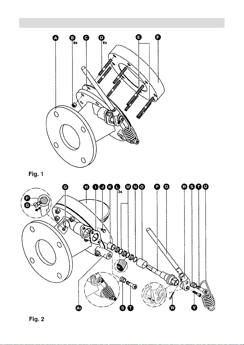
Parts Drawing
2
Page 3
Parts Drawing
3
Page 4

Important Safety Note
Tank container bottom valves must only be
installed by qualified staff. Consider the
relevant regulations for the prevention of
accidents.
Carefully read through installation instructions
before mounting the valve.
Use GESTRA genuine spare parts only.
Observe the corresponding regulations
established by the tank container operators
when loading or unloading the container.
Danger
When the upper dead centre is reached during
opening and closing by means of the operating
lever, the latter will instantaneously move
downwards or upwards. Persons who are
standing in close vicinity may be injured.
Closing with the aid of a release cord must
only be performed when nobody is in the
proximity of the operating lever. Do not
undertake any installation and maintenance
work unless the container is completely empty
and degassed. Escaping fumes and gas can
endanger life and health of the person
responsible for installation and maintenance
and cause material damage.
Function
The manually-operated container bottom valve
with spring-assisted lever ensures clear
indication of “OPEN” and “CLOSED” positions
and operates without the possibility of
intermediate positions.
The container valve type CV 10 is part of a
bottom loading and unloading system for
hazardous tank containers (TC) of IMO classes
1 and 2. It forms the first inner shut-off as
defined by TRTC 026, and is therefore part of
the pressure-containing shell.
Design
Valve range includes angled inlets of 30° and
45° (required to account for the different
geometries of the container bottoms).
The face-to-face dimensions (centre foot flange
to seating surface loading flange) have to
correspond to the varying overall lengths of
containers with different face-to-face
dimensions (min. 127 mm).
Alternatively with or without heating jacket
(required if the product requires heat).
■ CV 10/30
Angle of inclination: 30°
Face-to-face dimensions: as ordered
Heating jacket: as ordered
■ CV 10/45
Angle of inclination: 45°
Face-to-face dimensions: as ordered
Heating jacket: as ordered
Technical Data
Pressure/Temperature Ratings
DN/NPS 80/3"
Service pressure [bar] 4
[psig] 58
Min. service temperature [°C] –10
Max. service temperature [°C] 190
Test pressure [bar] 6
[psig] 87
Connection
Inlet flange angled at 30°/45°
For dimensions and further specifications
see data sheet.
Installation
Fitting (Fig. 1)
1. Insert fixing studs D and E into valve
mounting flange F.
2. Place gasket C onto the foot flange of the
CV 10 A and carefully tighten with fixing
studs. Take care not to damage the PTFE
envelope of the gasket.
3. Secure the CV 10 in position with the aid of
two nuts B.
4. Continue to screw in the two nuts until the
first threads of the top fixing stud D appear
at the rear of the foot flange. Screw the
corresponding nuts onto the fixing studs.
The restricted spacing to the valve body
makes a retro-fit of the nuts impossible.
5. Tighten all nuts B fingertight.
6. Tighten all nuts B gradually and in
diagonally opposite pairs by hand using a
spanner.
7. Tighten all nuts B gradually and in
diagonally opposite pairs with a torque of
36 + 2 Nm.
Dismantling
1. For the remov al of the valve proceed in
reverse order.
4
Page 5

2. The nuts B may be unscrewed in any
sequence you like.
Maintenance
The tank-container bottom valve does not
require any special maintenance.
Important Note
4. Remove spring first from reel S on the
operating lever and then from reel on the
body.
5. Completely unscrew socket-head cap screw
and pull lever out of the stem cone.
V
Note
Do not exchange the operating lever R when
installing several valves type CV 10.
Check the CV 10 when inspecting the tank
container, at least on the occasion of the
“Inspection and Examination” that takes place
every 2½ years. If necessary, service or
replace components.
1. Check torque applied to nuts and bolts and,
if required, re-tighten.
Torque [Nm]
Fixing nut
Hexagon-head cap bolt J7.5 + 0.5
Socket-head cap bolt
Socket head cap bolt
2. Check fixing of the operating lever and, if
necessary , replace pin W.
3. Check spring U and its support for damage
and smooth operation.
When the interior of the TC is examined
check the following:
1. Check support of valve disc H. The latter
must have sufficient play. If required clean
support and replace locking clip X.
2. Check gasket Y for damage and
deformation. Replace gasket at least every
2½ years.
B
V
T
36 + 2
32 ± 1
32 + 2
Danger
When loosening the socket-head cap screw
hold lever extension Q tight so that it cannot
be knocked downwards by the spring force.
V
Dismantling of spring and
operating lever (Fig. 2)
1. Open the valve.
2. Loosen socket-head cap screw V while
holding lever extension Q.
3. Move operating lever anticlockwise until the
lever extension hits the body dog
lever cannot be operated, loosen it by
delivering slight hammer blows to angle
lever R.
5
1. If the
A
Fitting of spring and operating lever
(Fig. 2)
1. Close CV 10 valve via valve disc H or
hexagon and keep it closed.
2. Insert operating lever into stem cone and fix
it with socket-head cap screw V so that it
can still be turned in the cone (loose fit).
Make sure that the cone and lever are free
of oil and grease.
3. Move operating lever anticlockwise until the
lever extension Q hits the body dog
4. Engage spring U first in reel S of
operating lever then in reel S located at the
body dog
5. Move operating lever clockwise upwards
until the markings on stem and angle lever
coincide (see Fig. 4).
6. Tighten socket-head cap screw V with a
torque of 32 ± 2Nm.
A
1.
A
1.
Danger
First dismantle spring U, as otherwise due to
the spring tension there is the risk of damage
and personal injury.
Replacement of spring supports
(reels) (Fig. 2)
1. Dismantle the spring U.
2. Unscrew the socket-head cap screws T.
3. Apply a light smear of lubricant to shaft and
threads of the new socket-head cap screws.
4. Push new reels S onto the screws T.
5. Introduce screws into angle lever R and
body dog
32 + 2 Nm.
6. Re-install spring U.
1 and tighten with a torque of
A
Page 6

Danger
Consider the relevant regulations for the
prevention of accidents. Do not exchange the
main valve seal unless the tank container is
completely empty and degassed. Be careful
when taking parts out of the water bath – they
are hot (risk of burns and scalds).
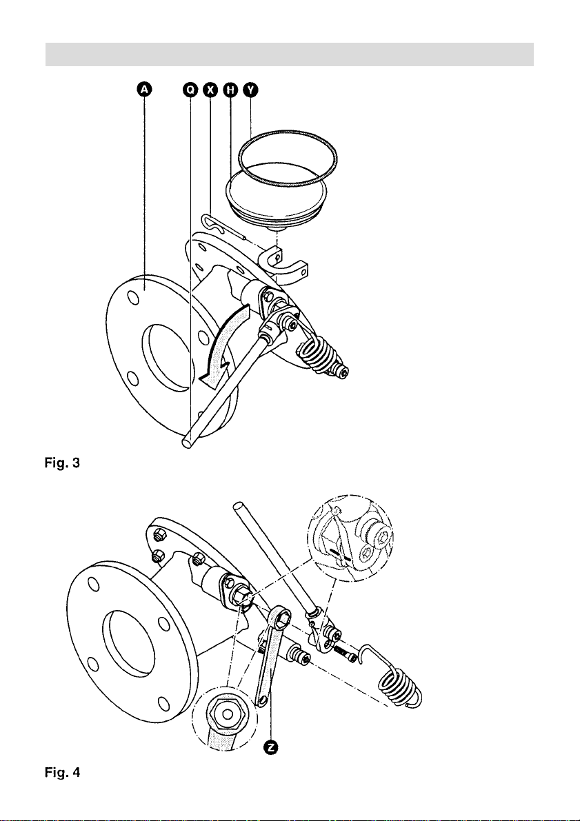
Fitting of lever for release cord
(“remote operator”) (Fig. 4)
1. Dismantle spring and lever as described.
2. Insert lever Z for remote quick-closing onto
stem P.
3. Refit spring and operating lever.
4. Laying of release cord on site by container
manufacturer.
Replacement of main valve seal
(Fig. 3)
1. Remove valve disc.
2. Use two needles or similar tools to lever the
O-ring Y out of the valve disc. Apply light
smear of lubricant to new O-ring.
3. Heat valve disc H and O-ring Y in the
water bath to a temperature of 90 – 95 °C.
4. Insert and press O-ring into groove.
5. Re-install valve disc.
Replacement of bearing bush and
stem sealing (Fig. 2)
1. Dismantle spring and operating lever as
described.
2. Loosen socket-head cap screw G so that
the lever can be shifted on the inner stem
hexagon.
3. Remove oval flange I.
4. Attach operating lever by means of socket-
head cap screw to stem P, pull stem out
of body A.
5. Remove bushes K and O.
6. Clean location hole for stem. Do not
damage sealing surfaces for O-rings
and M.
7. Insert new bushes K and O.
8. Apply lubricant to O-rings N + M and to
rings L and push them onto the stem.
Consider correct order and right position.
Remove any surplus lubricant on the stem
bearing surfaces.
9. Push stem with rings onto body A by to
and fro motions and then over the le ver.
The socket-head cap screw G must
coincide with the countersunk part of the
stem.
10. Tighten screw G with a torque of
7.5 + 0.5 Nm.
11. Mount oval flange I, tighten screws
with a torque of 7.5 + 0.5 Nm.
12. Refit and adjust spring and operating lever.
N
J
Spare parts
Item Designation Order No.
Collar bush 048759
K
14 x 18 x 18
Collar bush 048 761
O
22 x 15 x 32
Reel 048 762
S
Socket-head cap bolt 048 763
T
M 10 x 28
Socket-head cap bolt 012 488
G
M6 x 8
Hexagon-head cap bolt 013 821
J
M6 x 10
Socket-head cap bolt 011 555
V
M8 x 35
★NO-ring 048 766
★MO-ring 048 765
★YO-ring (main seal) 048 771
★LRing 048 767
Locking clip 048 984
X
Lever extension 048 776
Q
Pin 013 067
W
Spring (with sea-water 049 022
U
resistant coating)
Assembly parts: 049 053
nuts and bolts
Assembly parts: 048 780
gasket
Lever for release 049 061
cord (accessory)
6
Page 7

GESTRA Gesellschaften · GESTRA Companies · Sociétés GESTRA · Sociedades Gestra · Società GESTRA
GESTRA Gesellschaften · GESTRA Companies · Sociétés GESTRA · Sociedades Gestra · Società GESTRA
Vertretungen weltweit · Agencies all over the world · Représentations dans le monde entier · Representaciones en todo el mundo · Agenzie in tutto il mondo
Vertretungen weltweit · Agencies all over the world · Représentations dans le monde entier · Representaciones en todo el mundo · Agenzie in tutto il mondo
España
España
GESTRA ESPAÑOLA S.A.
GESTRA ESPAÑOLA S.A.
Luis Cabrera, 86-88
Luis Cabrera, 86-88
E-28002 Madrid
E-28002 Madrid
Tel. (091) 5152 032
Tel. 003491/5152032
Fax (091) 4 136 747; (091) 5 152036
Fax0 03491/413 674 7; 515 2036
E-mail: gestra@gestra.es
E-mail: gestra@gestra.es
France Portugal
France Portugal
Invensys Flow Control
Flowserve Flow Control S.A.S.
France SAS
10 Avenue du Centaure, BP 8263
10 Avenue du Centaure, BP 8263
F-95801 CERGY PONTOISE CEDEX
F-95801 CERGY PONTOISE
Tél. 003 31/34 432660
Tél. (01) 34.43.26.60
Fax 00331/34432687
Fax (01) 34.43.26.87
E-mail: gnation@flowserve.com
E-mail: gnation@gestra.fr
Italia
Italia
Invensys Flow Control Division
Italgestra S.r.l.
Italgestra S.r.l.
Via Carducci 125
Via Carducci 125
l-20099 Sesto San Giovanni (MI)
l-20099 S.S. Giovanni (MI)
Tel. 003902/241012.1
Tel. (02) 2410 12 1
Fax 0039 02/241012.460
Fax (02) 24 10 12460
E-mail: info@italgestra.it
E-mail: info@italgestra.it
Polska
Polska
GESTRA POLONIA Spolka zo.o.
GESTRA POLONIA Spolka z o. o.
Ul. Schuberta 104
Ul. Schuberta 104, P.O. Box 71
PL-80-172 Gdansk
PL-80-172 Gdansk
Tel. (058) 30610 02
Tel. 00 4858/ 3061002 oder 306 1010
Fax (058) 306 10 03
Fax 004858/30610 03 oder 3063300
E-mail: gestra@gestra.pl
E-mail: gestra@gestra.pl
GESTRA PORTUGUESA VALVULAS LDA.
GESTRA PORTUGUESA VALVULAS LDA.
Av. Dr. Antunes Guimarães, 1159
Av. Dr. Antunes Guimarães, 1159
P-4100 Porto
Porto 4100-082
Tel. (022) 6 19 87 70
Tel. 0035122/6 19 8770
Fax (022) 6 10 7575
Fax 0 0351 22/6107575
E-mail: gestra@gestra.pt
E-mail: gestra@gestra.pt
®
®
GESTRA GmbH
GESTRA GmbH
Postfach 10 54 60
Postfach 1054 60
D-28054 Bremen
D-28054 Bremen
Hemmstraße 130
Münchener Str. 77
D-28215 Bremen
D-28215 Bremen
Tel. +49 (0) 421 35 03-0
Tel. +49 (0) 421 35 03- 0
Fax+49 (0) 421 3503-3 93
Fax +49 (0) 421 35 03- 393
E-mail
gestra.gmbh@gestra.de
E-mail
gestra.gmbh@gestra.de
Internet www.gestra.de
Internet www.gestra.de
A Unit of Flowserve Corporation
An Invensys company
810654-00/401c · ©2000 GESTRA GmbH · Bremen · Printed in Germany
 Loading...