

Page 1
Automax Valve Automation Systems
Installation, Operation and Maintenance Instructions
Flowserve Corporation 765 South 100 East Phone: 801 373 3028
Flow Control Division Provo, Utah 84606-6160 Facsimile: 801 489 2228
Automation Business Unit www.flowserve.com Email: actuators@flowserve.com
APS2 Module
Installation Instructions
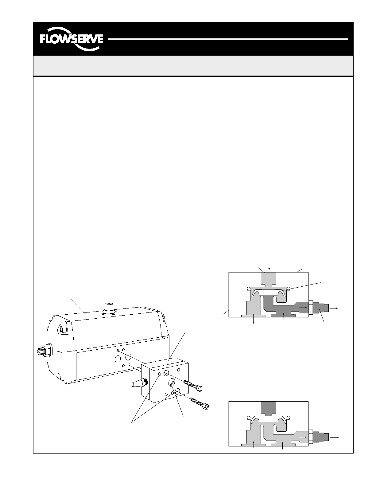
The Automax APS2 may be installed very easily to any
SuperNova series spring return actuator, with the
hardware supplied with the module.
1. Place each o-ring provided into the o-ring bore on
the rear of the module (the side with two large
ports.) Each o-ring should be completely seated
in the bore.
2. Place the actuator with the two ports facing you,
and the stem pointing up. Orient the APS2
module with the o-rings toward the actuator, and
the breather vent facing left.
3. The module will be mounted to the actuator, using
the two diagonal tapped holes next to the ports.
Align these holes with C-bored through holes of
the module, and mount with screws provided.
Directional valves may be line mounted to the APS2
by connecting the appropriate valve port to the 1/4"
NPT supply port on the front of the APS2. In addition,
the module supports the NAMUR mounting standard.
In this case, the directional valve should be positioned
such that the correct port is covering the APS2 supply.
Tapped holes are provided for NAMUR mounting.
Two o-rings are required for this arrangement
(2mm x 16mm o-ring size).
Operation
The Automax APS2 module works with remote line
mounted solenoid valves and diverts exhaust air from
between the pistons into the spring chamber. This
prevents corrosive atmosphere from being pulled into the
spring chamber.
Note: The APS2 can not be used in conjunction with
a positioner.
Temperature: -20°F to 180°F
Pressure: 20psig to 100psig
Media: Dry or lubricated non-corrosive gas
compatible with nitrile and silicone seals.
Exhaust: C∨ = 0.8 (Spring Return Stroke)
Inlet: C∨ = 1.2 (Pressure Stroke)
Actuator Pressurized
Pressure at supply port presses edge of diaphragm to
ring, allowing air flow around and under ring. Air flows
into piston port of actuator, compressing springs. Spring
side air exhausts out vent to atmosphere.
1/4" NPT
Supply Port
Upper Housing
with NAMUR Mounting
Diaphragm
SuperNova
NAMUR Mounting Pattern
LMR0016-0 (AUTO-16) 11/01
© 2001, Flowserve Corporation, Provo, Utah
APS2
1/4" NPT
Supply
Lower
Housing
Piston
Port
Spring
Port
Breather
Vent
Actuator Exhausted
Supply pressure is released and springs push on piston
to force air out piston port. Pressure forces diaphragm
up, covering supply port and revealing spring port. Air
flows into spring port, allowing clean air in instead of
contaminated air from the environment.
Page 1 of 2
Page 2
Automax Valve Automation Systems
Installation, Operation and Maintenance Instructions
Flowserve Corporation 765 South 100 East Phone: 801 373 3028
Flow Control Division Provo, Utah 84606-6160 Facsimile: 801 489 2228
Automation Business Unit www.flowserve.com Email: actuators@flowserve.com
Maintenance Instructions
Trouble Shooting the APS2
Actuator will not cycle.
1. Check for proper orientation of APS2.
2. Check for pinched diaphragm.
3. Check for plugged exhaust port.
Air leaks through breather exhaust when actuator
is held open.
1. Check for pinched diaphragm.
2. Check for diaphragm wear. Diaphragm should be
flexible with no tears.
3. Increase supply air pressure.
7
1
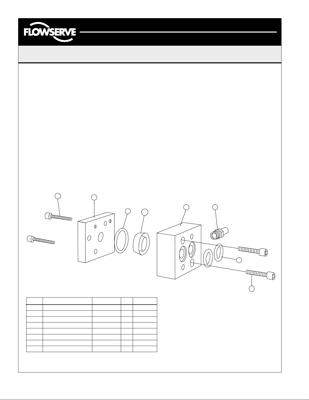
Assembly
1. Hold upper housing (2) with actuator ports side
down. Place large o-ring (4) into o-ring groove of
lower housing.
2. Place diaphragm (3) into center of bore of lower
housing. (See exploded view for diaphragm
orientation.)
3. Aligning pin in upper housing (1), place upper
housing on lower housing.
4. Fasten housing together with M5–.8 x 25 mm
SHCS (6) from lower housing side.
5. Attach breather vent (8) to lower housing, using a
sealant.
6. Place small o-rings (5) into o-ring grooves of
lower housing.
7. Mount to actuator with M5–.8 x 35mm SHCS (7).
Disassembly
Disassembly is reverse of assembly.
4
3
2
8
5
Standard Components
6
Part # Description Materials Qty. P/N
1 Upper Housing Aluminum 1 M610064
2 Lower Housing Aluminum 1 M610063
3 Diaphragm Polyurethane 1
4 O-Ring Nitrile 1 106073
5 O-Ring Nitrile 2 105775
6 M5––.8 x 25mm SHCS Steel 2
7 M5—.8 x 35mm SHCS Steel 2 106075
8 Breather Vent Bronze 1 106200
LMR0016-0 (AUTO-16) 11/01 Page 2 of 2
© 2001, Flowserve Corporation, Provo, Utah
 Loading...