

Page 1
Installation
Automax Valve Automation Systems
APEX 8000 High-Performance Positioner
FCD AXENIM0130-00
Principles of Operation:
This bulletin is designed to assist in installing, calibrating, troubleshooting and performing maintenance as required for
the APEX 8000 Series high-performance positioner.
Product users and maintenance personnel should thoroughly read and strictly follow the instruction s contained in this
bulletin prior to operating the positioner. Any questions concerning this product should be directed to a Flowserve
representative
To avoid possible injury to personnel or damage to valve parts, WARNING and CAUTION notes must be
strictly followed. Modifying this product, substituting non-factory parts or using maintenance procedures
other than outlined could drastically affect performance and be hazardous to personnel and equipm ent.
The APEX 8000 high-performance positioner is a two-stage device and is designed for use in control loops where fast
response is required. The APEX 8000 positioner is designed to be modular and use the P/P module for 3-15 psi input
signal or the NT 3000 Series Transducer Module for 4-20 mA input signal.
The APEX 8000 high-performance positioner is designed as a four-way device, but can easily be converted to a
three-way device by plugging one of the output ports.
NOTE: The APEX 8000 high-performance positioner must use the I/P NT 3000 Transducer. The I/P 2000 Transducer
is not acceptable for use with the APEX 8000 Series Positioner.
The APEX 8000 positioner can handle supply pressures up to 150 psi; thus, a supply regulator is usually not
required. However, a five micron air filter is required for pneumatic positioners and a coalescing filter is re quired for
I/P positioners.
NOTE: The air supply should conform to ISA Standard S7.3 (a dew point at least 18° F / -8° C below ambient
temperature, particle size below 5 microns, oil content not to exceed one part per million).
The APEX 8000 Series positioner features an adjustable gain of 400-1100:1. The medium gain setting is standard for
smaller actuators, while the high gain setting is used on larger actuators (refer to ‘Gain Adjustment Procedure’ section
for further details.)
OPERATION:
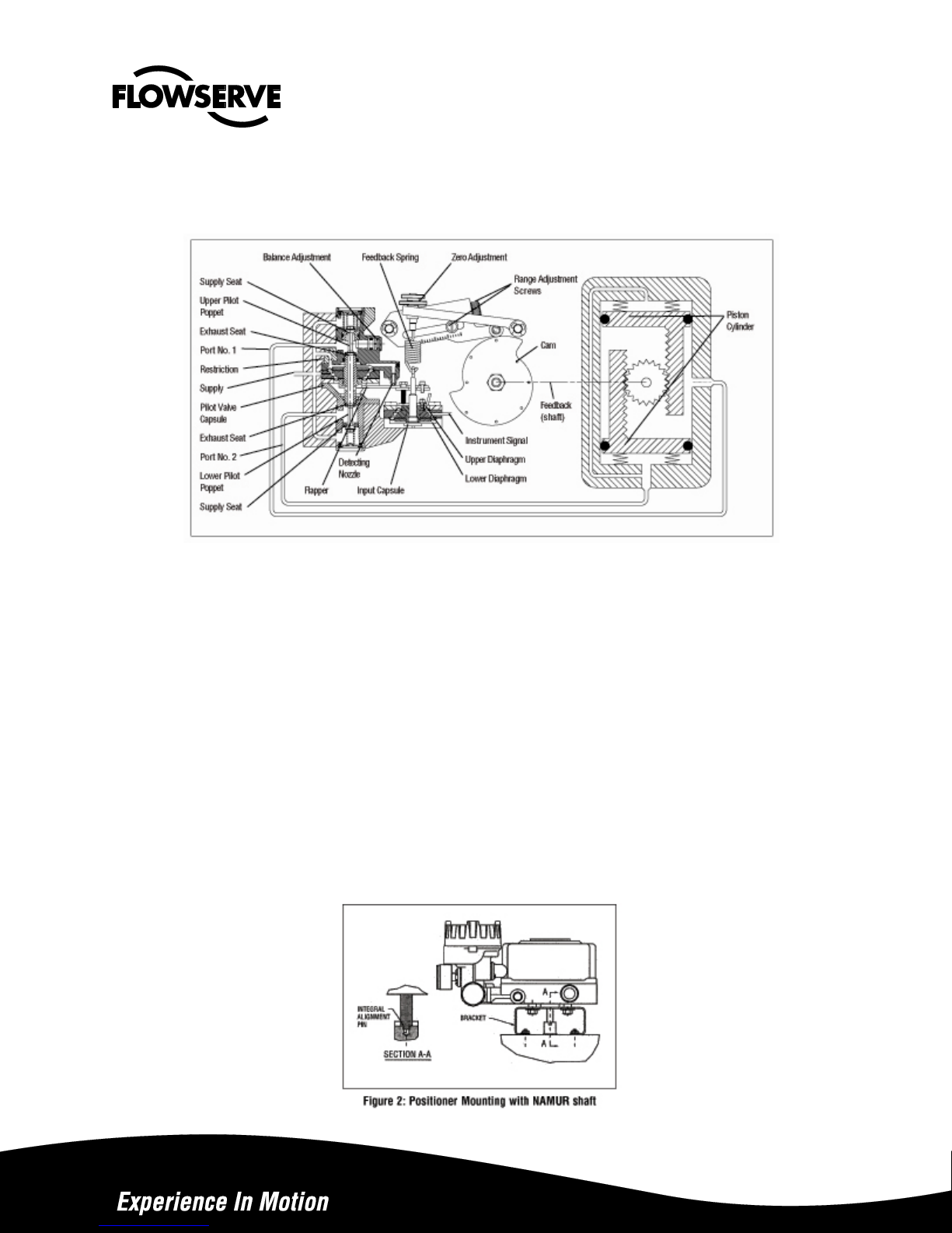
The positioner schematic (Figure 1) shows an APEX 8000 Series positioner connected for double-acting service on a
rotary rack-and-pinion actuator. Tension on the feedback spring provides feedback to the positioner, which varies a s
the stem position changes. The spring-loading force is applied throu gh the feed-back linkage and cam to the
positioner’s input capsule.
Instrument signal pressure is applied between the diaphragms in the input capsule. Therefore, the input capsule
serves as a force-balance member, matching the valve stem position (as measured by tension on the feedback
spring) to the instrument signal.
Operation
Maintenance
Page 2
When the opposing forces balance exactly, the system will be in equilibrium and the stem will be in the exact position
called for by the instrument signal. If the opposing forces are not in balance, the input capsule will move up or down
and, by means of the pilot-valves, will change the output pressures, moving the stem until the tension on the feedback
spring exactly opposes the instrument signal pressure
Figure 1: Apex 8000 Positioner Schematic for Air-to-Open
The sequence of operation is as follows: An increase in instrument signal pressure forces the input ca psule
downward. Displacement of the capsule in turn moves the flapper away from the detecting nozzle. This allows a larger
flow rate through the nozzle, decreasing the pressure exerted on the top of the pilot valve capsule.
Supply air biases the pilot-valve in an upward direction. As the capsule moves up, it will close the exhaust seat of the
upper pilot poppet and open the supply seat, which applies increased air pressure to the bottom cylinder port. At the
same time, the pilot-valve capsule will open the exhaust seat for the lower pilot poppet; thus, decreasing pressure to
the top cylinder port.
This difference in pressure will drive the piston outward, rotate the pinion and stretch the feedback spring until the
spring tension exactly opposes the force resulting from the instrument signal pressure. At this point, the flapper will be
moved toward the detecting nozzle to restore the pressure above the pilot-valve capsule to its equilibrium value. As a
force-balanced condition is approached, the pilot-valve capsule will be forced back to a neutral position where the
pilots are neither supplying air to, nor exhausting air from, their respective sides of the piston.
A decrease in instrument signal pressure reverses the described actions and cause a proportional inward movement
of actuator pistons and a reversal in pinion direction.
Page 3

Installation of APEX 8000 Series Positioner on Actuators:
The APEX 8000 can be installed on most sizes of rotary and linear actuators. Actuators can be either double acting or
spring return. Cams can be used for direct acting or reverse acting directions. These instructions apply to rotary actuators
only. For linear actuator mounting instructions, consult the factory.
NOTE: For retrofitting to an actuator equipped with an Apex positioner, the same bracket and bolting may be used.
NOTE: NAMUR mounting is available with the APEX 8000 position-er. When retrofitting the APEX 8000 positioner to an
actuator equipped with another positioner, remove the existing posi-tioner, tubing and associated bolting. See tubing
instructions in Connecting APEX 8000 Positioner Ports section.
Mounting Instructions for APEX 8000 with NAMUR Shaft Connection
1. Mount the bracket to the actuator. Finger tighten the bracket bolting.
2. If required, install a coupler on the actuator shaft. Make sure the shaft and coupler are centered. See Figure 2.
3. Verify the orientation of the actuator and coupler flats match the positioner flats on the end of the shaft. Loosen the
cam if necessary. (See “Cam Installations” instructions.)
4. Install the positioner onto the bracket. Make sure positioner shaft and coupler are engaged and cente red. Finger
tighten positioner bolts.
5. Proceed to “Connecting APEX 8000 Positioner Ports.”
Connecting APEX 8000 Positioner Ports:
1. For double acting actuators, connect positioner ports 1 and 2 to the actuator. Port 1 is always connected to the
actuator port used to drive the actuator away from its start or fail position (the factory cam setting is full clockwise at
minimum input signal).
NOTE: For single acting, spring return actuators, plug output port
2. Connect supply air to the port marked “SUPPLY.”
3. Connect air (for pressure inputs) or instrument tubing or wiring (for 4-20 mA inputs). For current inputs, the
terminal is marked (+) and (-) inside the I/P module. The I/P is factory calibrated and should not require adjustment. If adjustments are necessary, see “Calibrating I/P Module Zero and Span Settings” section
air pressure higher than 30 psi may damage the module gauge and instrument signal cap sule; a 3-15 psi instrument
signal is recommended on the pneumatic module.
4. Stroke actuator/valve two or three times to align positioner, coupler and actuator. With 50% input (actuator/valve
at 45 degrees), tighten all mounting bolts. Stroke actuator/valve again to verify there is no misalignment
throughout the stroke.
5. Calibrate valve and adjust cam if necessary. (See “Cam Installation” and “Positioner Calibration” instruction s.)
. Caution: Signal
Page 4
Cam Removal :
Disconnect cam return spring. With a wrench carefully placed on the output shaft (if necessary), loosen and remove the
jam nut. Remove pressure from the span arm by pushing it away from the cam. Remove the cam.
Cam Installation:
1. Make sure shaft is properly aligned with coupler or actuator.
2. Push span arm away from shaft to avoid pressure on the cam.
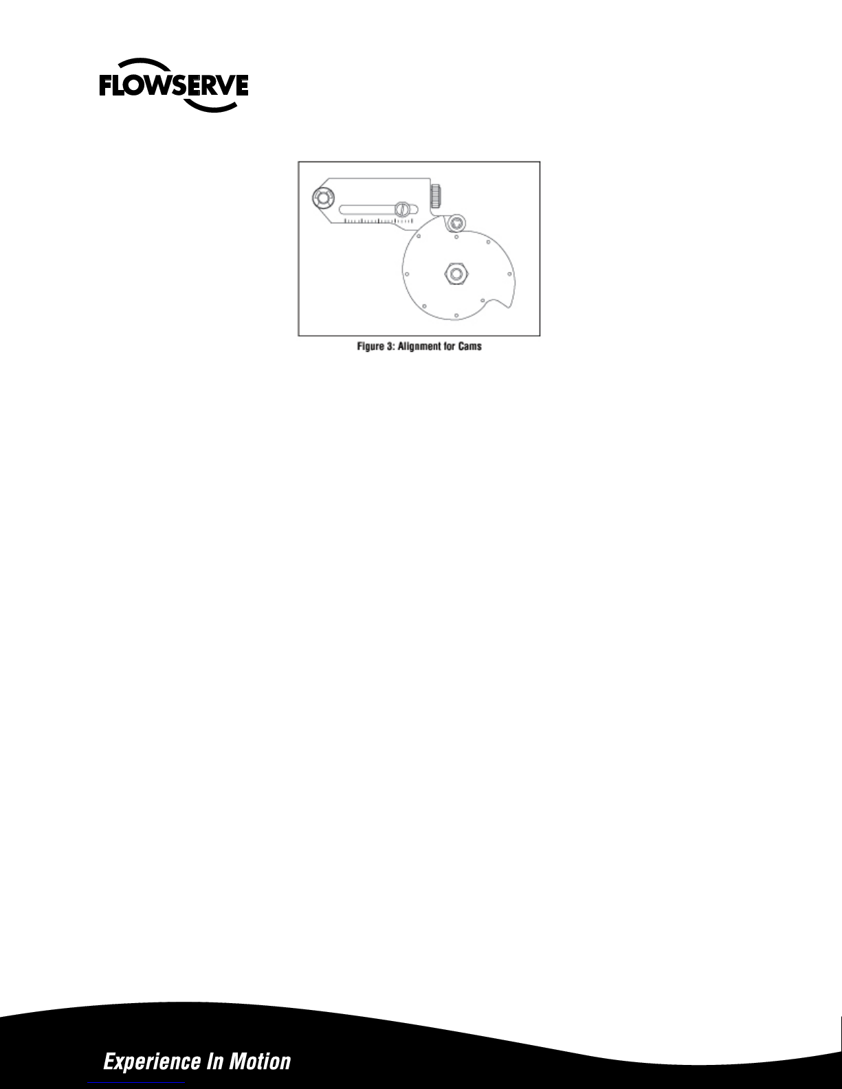
3. Place cam over the shaft with the appropriate characteristic facing up and closest to the span arm roller. “D”
represents direct-acting and “R” represents reverse acting.
4. Make sure the round mark on the left hand side of the characteristic curve is lined up with the span arm roller bearing.
See Figure 3
5. Tighten jam nut making sure cam does not rotate. Use a flat screwdriver to prevent cam rotation and shaft flats to prevent shaft rotation (if necessary)
6. Connect supply pressure to port marked ‘Supply.’stroke actuator/valve two or three times to align position with
actuator. With a 50 percent input signal, tighten all mounting bolts. Stroke actuator to verify proper alignment.
Position Calibration:
Introduction
APEX 8000 positioners are calibrated at the factory; however, due to shipping and handling, it may be necessary to check
the calibration before operating the valve. The APEX 8000 positioner can be calibrated to a range of 3-15; two-way split
range, 3-9, or 9-15; and three-way split ranging, 3-7, 7-11, 11-15 psi using the standard feedback spring.
WARNING: When stroking the actuator during calibration, keep hands, hair and clothing away from moving parts.
Failure to do so may cause serious personal injury.
Note: Positioners and I/Ps are calibrated at the factory. Use mechanical adjustments in positioner for calibration.
Zero and span on the I/P should not be used to calibrate the valve.
For calibration, refer to Figure 4 and proceed as follows:
Page 5
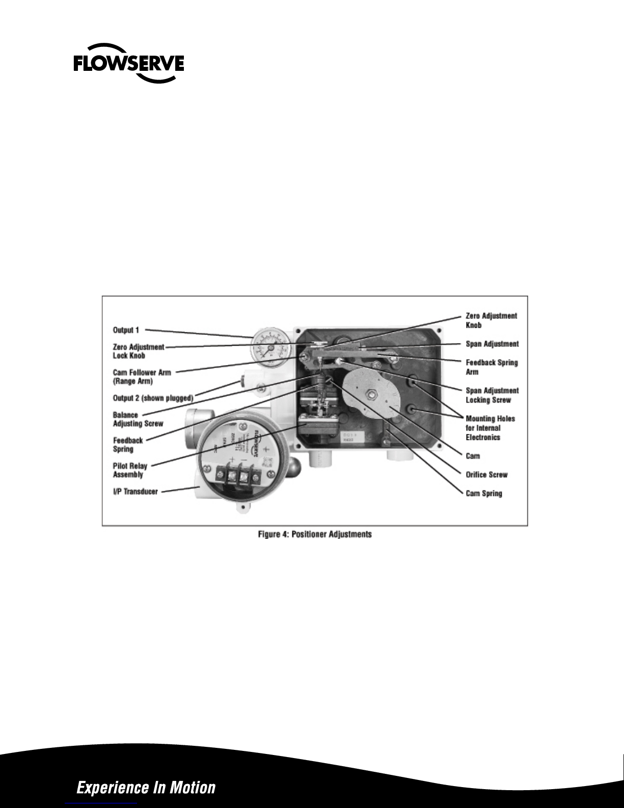
1. For 3-15 or 3-9 psi range, loosen by hand the zero adjustment locking knob and adjust the zero adjustment knob until
the valve begins to stroke with more than 3 psi signal (for 9-15 psi range adjust to 9 psi).
2. Loosen the span adjustment locking screw no more than 1/8 turn.
3. With a phillips screwdriver adjust the span adjustment so valve is at full stroke with more than 15 psi for 3-15 or 9-15
psi range (adjust to 9 psi for 3-9 psi range).
4. Return to 3 psi (or 9 psi for 9-15 psi range) and check the zero. Repeat steps 1-4 if necessary
5. Tighten the zero adjustment lock knob and span adjustment locking screw.
6. Use the same procedure for three-way split range.
7. Connect Cam return spring. See Figure 4.
Positioner Balance Adjustment
CAUTION: Balance pressure is 75 percent of the supply pressure and is the average pressure of output ports 1
and 2. Balance is preset at factory. However, if this adjustment becomes necessary, carefully make this
adjustment slowly, allowing the positioner to stabilize. Check after a short while to make sure balance pressure
is correct.
Balance adjustment is set at the factory and should not need adjustment. Balance adjustment (output pressure level)
permits the equilibrium pressure in both sides of the actuator piston to be raised or lowered. The average actuator
pressure level of output 1 or 2 is approximately 75 percent of supply pressure. For single-acting actuators, the balance
pressure should be left at the factory setting. If it is necessary to adjust the output pressure level, follow the procedure
outlined:
Page 6

1. If output pressure level is low, before adjusting, check for leaks in tubing connections between positioner and actuator
and check supply pressure.
2. Make certain there is no process force or pressure in the valve (The valve should be removed or isolated from the
process.)
3. On positioners without gauges, connect gauges to ‘output 1’ and ‘output 2’ lines
4. Remove rubber cap over balance adjustment screw. (See Figure 4.)
5. Apply full actuator operating pressure to positioner supply port.
6. Set input signal to midscale (9 psi for 3-15 psi span). Output pressure level cannot be adjusted with actuator against
valve seat or travel stops. Allow actuator pressure to stabilize.
7. Observe the pressure gauges. If reading is not correct, turn balance adjustment screw about 1/8 turn at a time and
wait about 20-30 seconds for pressure to stabilize (counterclockwise to increase pressure). Continue until output
pressure level of the higher pressure gauge is approximately 80 percent of supply.
8. Replace rubber cap over balance adjustment screw.
Figure 5: Close-up of Gain Adjustment Figure 6: Gain Adjustment
Gain Adjustment Procedure
The unique gain adjustment on the APEX 8000 positioner provides a means to increase or decrease the
responsiveness of the valve / actuator / positioner system. Increasing gain makes the valve more responsive and
faster, while decreasing gain makes the system less sensitive and slower to respond (with increased damping)
Page 7

1. Before adjusting the gain, place controller on manual and isolate the valve from the process.
2. Turn off supply air to control valve actuator.
3. Using a 5/64-inch allen wrench, loosen both upper and lower lock screws about one half turn. Do not loosen the
spacer nut. (See Figure 6.)
4. By grasping adjust lever, carefully rotate gain adjust assembly to desired position.
make sure both upper and lower gain adjust plates rotate together. When they are rotated to the new position, the
connecting spring should be perpendicular to the plates.
Caution: To avoid damaging gain adjust connecting sping mechanism, make sure both upper and lower gain
adjust plates rotate together. When they are rotated to the new position, the connecting sping shold be
perpendicular to the plates.
5. When the gain is set to the desired position, firmly tighten both lock screws.
6. Turn on the supply pressure. Check actuator responsiveness by providing a step signal to po sitioner. When gain is set
as desired, check valve zero and span calibration and re-calibrate if needed.
7. Return the valve to service.
Calibrating I/P Module Zero and Span Settings:
NOTE: Although calibration can be accomplished using the output pressure gauge on the I/P module, its accuracy is ±3
percent. The standard gauge should be removed only for calibratio n and more accurate calibration equipment of ±0.1
percent of span should be used. The pressure gauge port is 1/8-inch NPT. Calibration manifolds are avail able from the
factory (Part No. 97370).
1. Connect I/P module to a supply pressure between 30 to 150 psi.
2. Remove I/P module housing cover. (See Figure 7.)
WARNING: Be certain power to I/P module is disconnected before removing housing cover in explosive
atmospheres; otherwise personal injury may occur.
3. Before adjusting the zero and span, be certain the MPC feature is disabled. Refer to Step 7 in the ‘Adjusting the
Minimum Pressure Cutoff Feature’ section
4. Connect a current source to the terminal block on circuit board.
Page 8

Figure 7: KM82 Circuit Board Module
(housing cover removed)
NOTE: The zero and span adjustments are multi-turn potentiometers (pots) that have no stops on the ends of their travel;
however, they have a slip clutch to prevent damage from over-adjustment. The pots also make a clicking noise when they
have reached adjustment limits.
5. Apply a 4.0 mA signal to the input. Locate and adjust zero trim pot to achieve a 3.0 psi output. The output will increase
with clockwise rotation of the zero trim pot. If calibrating an I/P module with a 10-50 mA input signal, apply a 10.0 mA
signal to input.
6. Increase input signal to 20.0 mA (50 mA for 10-50 mA units). Locate and adjust span trim pot to achieve a 15.0 psi
output. The output will increase with clockwise rotation of the span.
7. Recheck zero setting by repeating Step 5. The span adjustment may affect zero setting.
8. Repeat Steps 5, 6 and 7 until proper adjustments are obtained.
Adjusting the Minimum Pressure Cutoff Feature:
The APEX 8000 positioner with I/P Transducer has a “Minimum Pressure Cutoff” (MPC) feature, which allows the user to
set the positioner. When the input signal falls below a user-adjustable current, the pressure output falls rap idly to approximately 1.7 psi, causing the valve to move to the failure position. This feature is generally used when the service requires a
tight shut off or to prevent throttling near the valve seat. To adjust this feature, refer to Figure 7 and perform the following:
NOTE: The following procedure applies only when the minimum pressure cutoff feature will be used.
NOTE: The zero and span settings of both the positioner and I/P transducer should be verified as accurate before the
minimum pressure cutoff feature is enabled and adjusted.
1. Connect the I/P module to a 30 to 150 psi air supply pressure.
2. Remove the I/P module housing cover.
WARNING: Be certain power to the I/P module is discon-nected before removing the housing cover in
explosive atmospheres; otherwise personal injury may occur.
Page 9

3. Connect an adjustable current source to the terminal block on the circuit board. Apply the desired input signal to the
positioner at which the output pressure is to fall to approximately 1.7 psi
3.7 to 8 mA.
. This signal can range from factory setting of
4. Turn the minimum pressure cutoff pot clockwise until the output pressure drops off Turn the minimum pressure cutoff.
5. Fine-tune the pressure drop-off point by increasing the input signal and then decreasing it through the desired shut-off
signal. Observe the signal value at which the pressure drops off. If the pressure drops off at a lower mA signal than
desired, turn the MPC pot counterclockwise. If the pressure drops off at a higher signal than desired, turn the MPC pot
clockwise.
6. Repeat Step 5 until the pressure drops off at the desired input sign.
7. To disable the MPC feature turn the minimum pressure cutoff pot (marked “MPC”) 20 turns counterclockwise or u ntil it
makes a clicking noise.
Positioner Maintenance:
NOTE: Refer to KM81 IOM for I/P module maintenance instructions.
For proper maintenance, proceed as follows:
1 Maintain a clean air supply, free of dust, oil and water. A coalescing air filter for I/P is required to ensure a clean air
supply. Check and maintain filter regularly.
2 Make sure all arms and levers move freely.
3 Check for loose parts.
4 Be sure there are no leaks in the air supply tubing fittings or connections.
5 Refer to the troubleshooting chart on page 9 in case of problems.\
Pilot Relay Disassembly and Reassembly:
The pilot relay is available as a complete unit and can be easily replaced (See Steps 2 and 18.) Before attempting to
correct any problem with the pilot relay assembly, obtain a positioner repair kit that contains the soft goods most
commonly required.
NOTE: Numbers in parentheses correspond to the numbers in Figure 8.
1 Remove the feedback spring (47) and rotate the span and zero arms (40, 46) out of the way.
2 Remove four screws (33) holding the pilot relay to positioner base (1). Remove relay from positioner.
3 Remove the nut (25) connecting the flapper assembly (21) to the signal capsule.
4 Remove four screws (32) holding the two halves of the pilot relay assembly together. Carefully pull the relay assembly
halves apart, making sure the flapper assembly
ٛ
(21) slides off the flapper adjustment screw (19) without damaging the signal diaphragm assembly (16). Pull the relay
diaphragm assembly (13) out of the other half of the relay body (9).
ٛ
5 With the relay assembly in two sections, remove two screws (22) holding flapper assembly (21) to the relay
diaphragm assembly (13). Remove the flapper.
Page 10

6 Remove diaphragm retaining plate (15) from relay diaphragm assembly (13) and relay plate (14)
7 Replace relay diaphragm assembly (13) with one from the positioner repair kit. Place the relay plate (14) between the
new diaphragms making sure the 1/16-inch diameter holes between the relay plate (14) and the diaphragm line up.
Position diaphragm retaining plate (15) on relay diaphragm assembly with rounded inner diameter edge against
diaphragm.
8 Attach flapper assembly (21) onto relay diaphragm assembly (13) using two screws (22) with a locking adhesive on
the threads. The flapper assembly should extend away from the 1/16-inch diameter hole through the relay plate. Make
sure lettering on flapper assembly is facing away from diaphragm.
9 With relay halves still apart, remove relay tube O-rings (8) from upper and lower bodies (9, 7) and repl ace them with
new O-rings (found in the positioner O-ring repair kit).
10 Remove rub ber cap (35) and balance adjust acrew cap (36) from upper relay body (9). Remove O-ring (38) from
balnce adjust screw and install new O-ring.
11 To remove and clean poppets (28), remove the retaining rings (31), poppet covers (27), O-rings (30), and poppet
springs (29) found at the end of each housing. After removing poppets, inspect them for dirt buildup or damage to
seating surfaces
12 The upper rel ay body (9) has a movable seat ring (34) which is adjusted with the balance adjust screw (36). This seat
is removed by pushing it out with a soft instrument such as a wooden dowel. Be careful not to damage seating
surface. Remove O-ring (37) from the seat ring (34).
13 Lubricate and replace the O-ring (37) on movable seat ring (34). Carefully reinstall the seat ring (34) into upper relay
body (9), being careful not to damage seating surface or O-rings.
14 Reinstall pop pets (28), poppet springs (29), Seat Spring (39), O-rings (30), and poppet covers (27) before installing
retaining rings (31).
15 If signal diaphragm assembly (16) is damaged, proceed as follows: With relay halves still apart, remove four screws
32) holding signal diaphragm assembly (16) to the pilot relay assembly. Remove locking screw (23), washer (24),
adjustable gain lower plate (26), and diaphragm plate. Remove signal diaphragm assembly (15) and remove relay
plate (14) from between the diaphragms.
care to align the 1/16-inch diameter holes between the diaphragms and the relay plate (14). Replace diaphragm plate
(15), adjustable gain lower plate (26), washer (24), and locking screw, but do not tighten. Replace four screws (32)
that hold signal diaphragm assembly together.
16 Pack O-ring grea se into the O-ring groove and lightly lubricate the outside of the relay tube on diaphragm relay
assembly (13). Make sure small holes on the side of the tube do not get plugged with grease. Insert the relay
diaphragm assembly (13) as assembled in steps 7 and 8 into the lower relay half. Carefully align the flapper (21) over
the adjustable gain screw (19) and replace and tighten the nut (25).
17 Fasten the two halves of the relay together using four long screws (32). Make sure the 1/16-inch diameter holes in the
relay diaphragm assembly (13) and the upper relay b ody
screws (23, 25). See gain procedure.
18 Replace screen (110) and O-rings (8,12) found on the back of the pilot relay before reinstalling the pilot relay on the
base of the positioner with four screws (33). Clean out any debris lodged in screen or replace with a new one.
19 Replace sp an arm and zero arm (40, 46) and feedback spring (47).
.
Place relay plate (14) between the diaphragms on the new assembly taking
(9) line up. Set gain to desired setting and tighten locking
Page 11

Troubleshooting APEX 8000 Positioners
Failure Probable Cause Corrective Action
Valve won’t
stroke, no
excessive air
is exhausting
from
positioner
Valve won’t
stroke,
excessive air
exhausting
from
positioner
1. Tubing to wrong ports
2. Cam action reversed
3. Feedback lever arm is stuck
4. low air supply
5. Relay tube stuck
6. Balance adjust screw not adjusted correctly
7. I/P module filter plugged
8. I/P module failure
9. I/P mounting bolts loose
10.I/P pressure signal blocked
1. A diaphragm in relay assembly burst
2. One of the poppets is stuck
3. Internal control valve problem
4. Damaged relay O-rings on relay tube
5. Blocked passageways in relay
1. Re-tube to correct ports (see “installation section).
2. Refer to “installation” section and reverse cam
3. Work with lever arm until it turns freely
4. Increase air supply to recommended value
5. Disassemble relay assembly and work relay tube free. Lightl y lubricate
if necessary
6. Adjust balance pressure with adjusting screw
7. Remove I/P module and replace filter
8. Replace I/P module
9. Tighten mounting bolts
10. Remove I/P module and clear passageway; replace O-ring if necessary
1. Replace relay assembly or replace diaphragms
2. Remove relay assembly/poppet cover; free stuck poppet
3. Refer to instructions or check for actuator tubing leaks
4. Disassemble relay and replace O-rings
5. Disassem ble relay and check small holes under diaphragms; clean if
clogged
Actuator goes
to full signal
position
regardless of
signal
Calibration 1. Loose positioner mounting
Excessive air
consumption
(other than
normal
exhaust)
Actuator
strokes very
slowly in one
direction only
Erratic
operation
Excessive
overshoot
1. Broken feedback spring
2. Link age is disconnected or stuck
3. Orifice is clogg ed by water, oil or dust in air
supply
4. Bent flapper, damaged nozzle
5. I/P module failure
6. Clogge d orifice screen
2. Loose linkage
3. Loose zero adjustment locking knobs
4. Wear of arms or pins
5. I/P mounting bolts loose
6. Stroke has change in valve
1. Air leakage from manifold rings between
relay and base
2. Air leakage from tubing
3. Leaky cylinder piston O-rings
4. Air leakage from relay
1. Connection between signal capsule and
flapper misadjusted
2. Tubing to cylinder is restricted
3. Balance pressure low
1. Dirt buildup on relay poppets or seats
2. Dirt buildup on relay tube
3. Clogged ports / passageways in relay
4. Faulty I/P module
5. Clogged orifice screw
6. Mechanica l binding in linkage or internal
galling in valve
7. Clogged orifice screen
1. Restriced air fl ow to positioner
2. Balance pressure not set correctly
3. Gain is set too high
1. Replace feedback spring
2. Check and tighten bolts/nuts in linkage. Make sure linkage dones not
hang up; grease ping that rides in follower arm slot
3. Remov e orifice screw and carefully clean orifice hole
4. Straighten flap per or replace damaged parts
5. Replace I/P module
6. Remov e relay and clean ore replace orifice screen
1. Remove cover and check three screws holding positioner to bracket;
check two bolts holding bracket to yoke
2. Tighten nuts and bolts on linkage and stem clamp
3. Tighten zero adjustment locking knob; re-calibrate if necessary
4. Replace worm arms, pins; grease appropriately
5. Tighten I/P mounting bolts
6. Refer to valve maintenance instructions
1. Tighten screws holding relay assembly together and/or replace O-rings
2. Tighten or replace tubing fittings
3. Replace O-rings in cylinder
4. Disassemble relay and check and replace dynamic O-rings next to tube
if necessary
1. Adjust gain according to Figure 6 or until actuator strokes approximately
equal speed in both directions. Verify alignment of upper and lower gain
plates. Make sure spacer nut is tightened.
2. Inspect tubing/fittings for restriction and replace if necessary
3. Adjust balance pressure according to page 5
1. Disassemble; clean poppets and seats; add air filter or change filter
2. Disassem ble; clean relay and lightly lubricate; replace O-rings if
necessary; add air filter or change filter
3. Disassem ble, inspect and clean all ports and passageways
4. Replace the I/P module
5. Remov e orifice screw and carefully clean orifice
6. Tighten linkage or refer to valve maintenance instructions
7. Remov e relay and clean or replace orifice screen
1. Adjust air supply as needed
2. Adjust balance pressure according to page 5
3. Lower gain mechanism until overshoot is minimized
Page 12

Page 13

Page 14

Flowserve Corporation
1978 Foreman Drive
Cookeville, Tennessee, USA, 38501
931 432-4021
Flowserve Flow Control UK Ltd
Haywards Heath, West Sussex, Uk
44 (0)1444 314400
Flowserve Corporation
12 Tuas Avenue 20
Singapore
68798900
Flowserve Corporation
Rua Tocantins, 128
São Caetano do Sul, SP, Brazil
55 11 2169-630
0
Bulletin FCD AXENIM0130-00
To find your local Flowserve representative please
use the Sales Support Locator System found at
www.flowserve.com
Or call toll free: 1-931-432-4021
Flowserve Corporation has established industry leadership in the design and manufacture of its products. When properly selected, this
Flowserve product is designed to perform its intended function safely during its useful life. However, the purchaser or user of Flowserve products
should be aware that Flowserve products might be used in numerous applications under a wide variety of industrial service conditions. Although
Flowserve can provide general guidelines, it cannot provide specific data and warnings for all possible applications. The purchaser/user must
therefore assume the ultimate responsibility for the proper sizing and selection, installation, operation, and maintenance of Flowserve products.
The purchaser/user should read and understand the (INSERT OFFICIAL USER INSTRUCTION TITLE) instructions included with the product,
and train its employees and contractors in the safe use of Flowserve products in connection with the specific application.
While the information and specifications contained in this literature are believed to be accurate, they are supplied for informative purposes only
and should not be considered certified or as a guarantee of satisfactory results by reliance thereon. Nothing contained herein is to be construed
as a warranty or guarantee, express or implied, regarding any matter with respect to this product. Because Flowserve is continually improving
and upgrading its product design, the specifications, dimensions and information contained herein are subject to change without notice. Should
any question arise concerning these provisions, the purchaser/user should contact Flowserve Corporation at any one of its worldwide operations
or offices.
For more information about Flowserve Corporation, contact www.flowserve.com
or call USA 1-800-225-6989.
 Loading...