

Page 1
Allpac MP
Flow Solutions Division
BW Seals
Durametallic Seals
Pacific Wietz Seals
Pac-Seal
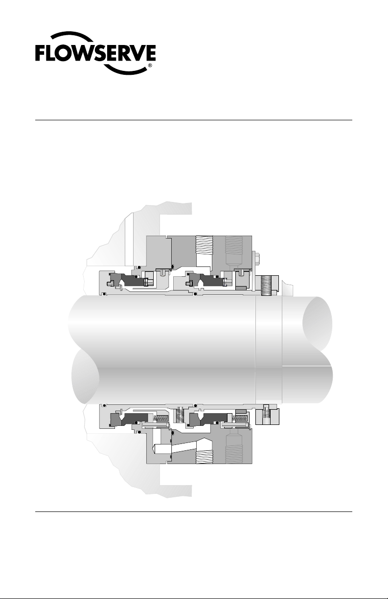
Dual-inline, cartridge seal
for multiphase applications
Installation Instructions
Page 2
Introduction
The Allpac MP is a dual-inline, cartridge seal specifically designed for multiphase twinscrew pumps. Four mechanical seal assemblies are installed on one pump. Each seal is
identical; they are designed to fit in any location on the pump.
1 Equipment Check
1.1 Follow site safety regulations prior to equipment disassembly.
• Lock out motor and valves
• Wear designated personal safety equipment
• Relieve any pressure in the system
• Consult site MSDS files for hazardous material regulations
1.2 Disassemble equipment to allow access to seal installation area.
1.3 Remove all burrs and sharp edges from the shaft or sleeve including sharp edges
of keyways and threads. Replace shaft or sleeve if worn in the sleeve gasket
area. Make sure the seal housing bore and face are clean and free of burrs.
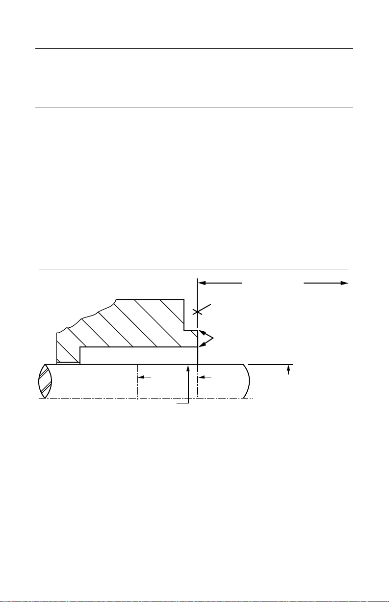
1.4 Check requirements for shaft, sleeve, and seal housing, see Figure 1.
Seal Chamber Requirements
To first obstruction
Face of seal housing to be square to the axis
of the shaft to within .005 inch (0.13 mm) FIM
and have a √63 µ inch (1.6 µm) R
better
Concentric to within .005 inch (0.13mm) FIM
Seal housing bore to have a √125 µ inch
(3.2 µm) Ra finish or better
Scribe
Mark B
Sleeve or shaft finish to be
√32 µ inch (0.8 µm) Ra or better
• Bearings must be in good condition.
• Maximum lateral or axial movement of shaft (end play) = .010 inch (0.25mm) FIM
• Maximum shaft runout at face of seal housing = .003 inch (0.07mm) FIM
• Maximum dynamic shaft deflection at seal housing = .002 inch (0.05mm) FIM
of shaft or sleeve O.D.
Scribe
Mark A
+.000 inch (+.000mm) API 610
Figure 1
finish or
a
1.5 Check assembly drawing included with the cartridge seal for materials of construc-
tion, dimensions, and piping connections.
1.6 Check shaft or sleeve O.D., box bore, and distance to the first obstruction to
ensure that they are dimensionally the same as shown on the seal assembly
drawing.
1.7 Check gland pilot and bolt holes to ensure they are adaptable to the equipment
and are the same as shown on the assembly drawing.
2
© Copyright 2002 Flowserve Corporation
Page 3

1.8 Handle all seal parts with care, they are manufactured to precise tolerances. The
contacting surfaces of the rotating and stationary seal faces must be treated with
particular care. These two surfaces are lapped flat to within three helium light bands
(34.8 millionths of an inch). Keep the seal faces perfectly clean at all times.
2 Allpac MP Seal Installation
2.1 Lubricate the shaft or sleeve lightly with silicone lubricant before installing any seal
parts.
2.2 Lubricate the two sleeve gaskets before installing them in their grooves in the sleeves.
2.3 Lubricate the flange gasket before installing onto the pilot diameter on the seal
cartridge.
2.4 Back out the drive collar set screws slightly so that no portion of them extends
inward past the sleeve ID.
2.5 Install the complete cartridge seal assembly on the shaft and position it with the
seal oriented toward the pump. If at any time the seal requires a significant amount of
force to position correctly, STOP, BACK UP, and assess the situation.
2.6 Position the cartridge flange against the seal chamber face and tighten the gland
stud nuts evenly in a star pattern. The nuts can be torqued using ordinary wrenching
techniques.
2.7 Adjust the bearings, coupling and pump rotating assembly so that the shaft is in
its operating axial position. Any subsequent axial adjustment of the shaft requires
resetting of the seal.
2.8 Tighten the drive collar set screws to the value specified on the assembly drawing.
Improper installation torque can damage the screws or shaft or result in lower axial
thrust retention of the drive collar.
2.9 Loosen the setting plate fasteners and slide the setting plates away from the drive
collar and sleeve as far as possible. Tighten the setting plate fasteners so that the
setting plates do not come loose during operation.
3 Barrier System Piping
3.1 Each dual cartridge seal has pipe ports labeled as shown in the assembly drawing.
3.2 The Allpac MP seal is designed to be operated with the seal flush and support systems
as defined on the assembly drawing.
4 Operation
4.1 During the first hour of operation, seal performance should be monitoredvery
closely:
• The temperature rise of the barrier fluid should be steady and should level out
after an hour of operation. A quickly rising temperature or a temperature that does
not seem to be leveling off signals a problem and should be thoroughly investigated.
• A sudden rise or decrease in barrier fluid, or a significant color change of barrier
fluid signals off-design leakage and should be thoroughly investigated.
3
Page 4

• A leakage rate of more than 30 drops per minute of the outboard seal signals off-
design leakage and should be thoroughly investigated.
• Excessive vibration of the pump should be investigated immediately.
5 Repairs
This product is a precision sealing device. The design and dimension tolerances are critical
to seal performance. Only parts supplied by Flowserve shall be used to repair the seal.
These are available from numerous Flowserve stocking locations. To order replacement
parts, refer to the part number, material code and description listed on the assembly
drawing.
Decontaminate the seal assembly and return it to Flowserve with an order marked
“Repair or Replace.” A signed certificate of decontamination must be attached.
A Material Safety Data Sheet (MSDS) must be enclosed for any product that came in
contact with the seal. The seal assembly will be inspected and, if repairable, it will be rebuilt,
tested and returned in its original condition.
All Flowserve Corporation, Flow Solutions Division, products must be installed in accordance with Flowserve
installation instructions. Failing to do so or attempting to change or modify Flowserve products will void
Flowserve’s limited warranty. Flowserve’s limited warranty is described fully in Flowserve’s Standard Terms and
Conditions of Sale. Flowserve makes no warranty of merchantability or fitness for a particular purpose and in
no event shall Flowserve be liable for consequential or incidental damages.
Flowserve Corporation Flow Solutions Division
Primary Worldwide Flow Solutions Division Locations Licensees, authorized agents, and affiliated companies located worldwide
United States
Kalamazoo, MI
Phone 269-381-2650
Fax 269-381-8368
Edmonton, Alberta
Phone 780-463-7958
Fax 780-450-1241
Canada
Scarborough, Ontario
Phone 416-292-2877
Fax 416-292-5190
Singapore Japan
Phone 65-746-4318
Fax 65-747-1963
Printed in U.S.A.
Tlaxcala
Phone 52-2-461-6791
Fax 52-2-461-6847
Sao Paulo
Phone 55-11-4066-8600
Fax 55-11-4066-7014
Netherlands
Roosendaal
Phone 31-165-581400
Fax 31-165-552622
Osaka
Phone 81-720-85-5571
Fax 81-720-85-5575
www.flowserve.com
ISO 9000
Certified
Argentina
Villa Martelli
Phone 54-11-4709-6800
Fax 54-11-4709-7072
GermanyBrazilMexico
Dortmund
Phone 49-231-6964-0
Fax 49-231-6964-248
Australia
Marayong NSW
Phone 61-2-8822-7100
Fax 61-2-9679-7511
FIS156
ORG 07/02 USA
 Loading...